CN213425558U - Oil field water injection integrated control cabinet - Google Patents
Oil field water injection integrated control cabinet Download PDFInfo
- Publication number
- CN213425558U CN213425558U CN202021434707.0U CN202021434707U CN213425558U CN 213425558 U CN213425558 U CN 213425558U CN 202021434707 U CN202021434707 U CN 202021434707U CN 213425558 U CN213425558 U CN 213425558U
- Authority
- CN
- China
- Prior art keywords
- fan
- cabinet
- cabinet body
- fixed
- gear
- Prior art date
- Legal status (The legal status is an assumption and is not a legal conclusion. Google has not performed a legal analysis and makes no representation as to the accuracy of the status listed.)
- Active
Links
Images


Landscapes
- Separation Of Particles Using Liquids (AREA)
Abstract
The utility model discloses an oil field water injection integrated control cabinet, including dust collecting tank, the cabinet body, equipment fixing room and division board, the bottom of the internal portion of cabinet is provided with the dust collecting tank, and the bottom mounting of dust collecting tank inside has the air exhauster, the top of the internal portion of cabinet is provided with the equipment fixing room, and one side of the internal portion of equipment fixing room is fixed with first division board, the central position department of first division board is fixed with first fan, the top of the cabinet body both sides all articulates there is first cabinet door, and the bottom of the cabinet body both sides all articulates there is the second cabinet door. The utility model discloses an install the cabinet body, equipment fixing room, first division board, second division board, motor, first fan, second fan, pivot, first gear and second gear for first fan rotates with the second fan simultaneously, and one side and the top of the cabinet body all are provided with radiating area and louvre, make the hot gas flow pass through the louvre external portion of cabinet of discharging, and ventilation cooling is effectual.
Description
Technical Field
The utility model relates to a switch board technical field specifically is oil field water injection integrated control cabinet.
Background
The oilfield flooding is one of important means for supplementing energy to stratum and improving oilfield recovery ratio in oilfield development process, and water with satisfactory quality is injected into an oil layer from a flooding well by utilizing flooding equipment so as to keep the pressure of the oil layer, and the oilfield flooding needs to use a comprehensive control cabinet to carry out related operations, but most of the existing comprehensive control cabinets have partial defects, specifically the following steps;
1. the existing comprehensive control cabinet has poor heat dissipation effect, can generate a large amount of heat after working for a long time, and is easy to cause internal parts to be heated and aged;
2. most of the existing comprehensive control cabinets do not have the moisture-proof function, when the humidity of air is increased, water mist is easily condensed in the cabinet body to form water drops, and the risks of electric leakage and equipment burnout are increased;
3. most of the existing integrated control cabinets do not have the dust removal function, and dust, impurities and the like generated in the control cabinets are not beneficial to collection and treatment.
Disclosure of Invention
The utility model aims at providing an oil field water injection integrated control cabinet to solve the problem that the radiating effect that proposes among the above-mentioned background art is poor, the security is not high and be unfavorable for the dust removal.
In order to achieve the above object, the utility model provides a following technical scheme: oil field water injection integrated control cabinet, including dust collecting tank, the cabinet body, equipment fixing room and dehumidification board, the bottom of the internal portion of cabinet is provided with the dust collecting tank, and the bottom mounting of dust collecting tank inside has the air exhauster, the top of the internal portion of cabinet is provided with the equipment fixing room, and one side of the internal portion of equipment fixing room is fixed with first division board, the central point department of putting of first division board is fixed with first fan, the top of the internal portion of equipment fixing room is fixed with the second division board, and the central point department of putting at second division board top is provided with the second fan, the top that second fan one side was kept away from to first division board is fixed with the motor, and the output of motor is fixed with the pivot, be connected with first fan through belt pulley mechanism in the pivot, the top of the cabinet body both sides all articulates there is first cabinet door, and the bottom of the cabinet body both sides all.
Preferably, a second gear is fixed on the rolling shaft of the second fan, a first gear is fixed on the rotating shaft, and the first gear is meshed with the second gear, so that the motor can drive the second fan to rotate conveniently.
Preferably, one side of the cabinet body is provided with a heat dissipation area, and heat dissipation holes are uniformly distributed in the heat dissipation area, so that ventilation and heat dissipation are facilitated.
Preferably, the bottom end in the equipment installation chamber is provided with a mesh grid, and the mesh grid is communicated with the top of the dust collection groove, so that dust removal is facilitated.
Preferably, one side of the inside of the equipment installation chamber is provided with a fixed net frame, the upper end and the lower end of the fixed net frame are respectively fixed with a sliding block, the two ends of the inside of the equipment installation chamber are respectively fixed with a sliding groove matched with the sliding block, the fixed net frame forms a sliding disassembly structure through the sliding block and the sliding groove, and the fixed net frame is convenient to install and disassemble.
Preferably, the fixed net frame is internally provided with a dehumidifying plate made of porous silica gel with a large surface area, so that the device can conveniently dehumidify the inside.
Compared with the prior art, the beneficial effects of the utility model are that:
(1) this oil field water injection integrated control cabinet is through installing the cabinet body, the equipment fixing room, first division board, the second division board, including a motor, an end cap, a controller, and a cover plate, the pivot, first gear and second gear, the motor drives the pivot and rotates, make the epaxial first gear of pivot rotatory, first gear and second gear interlock, it is rotatory to drive the second gear, fixed connection on second gear and the second fan, and then make the second fan rotate, roller bearing on the first fan passes through belt pulley mechanism and is connected with the pivot simultaneously, make first fan and second fan rotate simultaneously, one side and the top of the cabinet body all are provided with radiating area and louvre, make the hot gas flow discharge cabinet body outside through the louvre, ventilation cooling effect is good.
(2) This oil field water injection integrated control cabinet is through installing fixed net frame, dehumidification board, slider and spout, and the inside of fixed net frame is provided with the dehumidification board, and the dehumidification board is the very big porous silica gel material of surface area, and the moisture of air is absorbed under surface adsorption and capillary condensation, reaches the purpose of the internal portion dehumidification of cabinet, in addition, through sliding block in the spout, can take out fixed net frame and dehumidification board and dismantle the change.
(3) This oil field water injection integrated control cabinet is provided with the net bars through the bottom at the equipment fixing room, install the dust collecting tank in the bottom of the internal portion of cabinet, the dust collecting tank is linked together with the net bars, the inside bottom of dust collecting tank is provided with the air exhauster, produce suction when the air exhauster is opened, the indoor dust impurity of equipment fixing falls into the dust collecting tank through the net bars and collects, do benefit to the follow-up dust impurity centralized processing with the indoor of equipment fixing, the outside of the cabinet body bottom evenly is provided with the dust screen, avoid the dust impurity in the dust collecting tank to spill the polluted environment.
Drawings
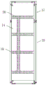
Fig. 1 is a schematic front view of a cross-sectional structure of the present invention;
FIG. 2 is a schematic view of the front view of the present invention;
FIG. 3 is a schematic side view of the structure of the present invention;
fig. 4 is a schematic view of the side view structure of the fixed screen frame of the present invention.
In the figure: 1. a dust collecting groove; 2. a mesh grid; 3. a first fan; 4. a first partition plate; 5. a belt pulley mechanism; 6. a motor; 7. a second partition plate; 8. a first gear; 9. a second gear; 10. a second fan; 11. a rotating shaft; 12. a chute; 13. fixing the screen frame; 14. a cabinet body; 15. an equipment installation room; 16. an exhaust fan; 17. a first cabinet door; 18. a second cabinet door; 19. a heat dissipation area; 20. heat dissipation holes; 21. a slider; 22. and (7) a dehumidification plate.
Detailed Description
The technical solutions in the embodiments of the present invention will be described clearly and completely with reference to the accompanying drawings in the embodiments of the present invention, and it is obvious that the described embodiments are only some embodiments of the present invention, not all embodiments. Based on the embodiments in the present invention, all other embodiments obtained by a person skilled in the art without creative work belong to the protection scope of the present invention.
Referring to fig. 1-4, the present invention provides an embodiment: the oilfield water injection comprehensive control cabinet comprises a dust collecting tank 1, a cabinet body 14, an equipment installation chamber 15 and a dehumidifying plate 22, wherein the bottom end inside the cabinet body 14 is provided with the dust collecting tank 1, an exhaust fan 16 is fixed at the bottom end inside the dust collecting tank 1, the top end inside the cabinet body 14 is provided with the equipment installation chamber 15, the bottom end inside the equipment installation chamber 15 is provided with a net grid 2, and the net grid 2 is communicated with the top of the dust collecting tank 1;
after working for a period of time, the exhaust fan 16 can be started to generate suction force, dust and impurities in the equipment installation chamber 15 are adsorbed into the dust collection groove 1 through the mesh grid 2 for collection, so that subsequent centralized treatment is facilitated, and the dust screen is uniformly arranged on the outer side of the bottom of the cabinet body 14 to prevent the dust and impurities in the dust collection groove 1 from splashing to pollute the environment;
a first partition plate 4 is fixed on one side inside the equipment installation chamber 15, a first fan 3 is fixed at the central position of the first partition plate 4, a second partition plate 7 is fixed at the top end inside the equipment installation chamber 15, a second fan 10 is arranged at the central position of the top of the second partition plate 7, a motor 6 is fixed at the top end of one side, far away from the second fan 10, of the first partition plate 4, a rotating shaft 11 is fixed at the output end of the motor 6, and the rotating shaft 11 is connected with the first fan 3 through a belt pulley mechanism 5;
a second gear 9 is fixed on a rolling shaft of the second fan 10, a first gear 8 is fixed on the rotating shaft 11, the first gear 8 is meshed with the second gear 9, a heat dissipation area 19 is arranged on one side of the cabinet body 14, and heat dissipation holes 20 are uniformly distributed on the heat dissipation area 19;
the motor 6 can drive the rotating shaft 11 to rotate conveniently, so that the first fan 3 and the second fan 10 can rotate simultaneously, through holes are uniformly formed in the first partition plate 4 and the second partition plate 7, hot air inside the cabinet body is discharged out of the cabinet body 14 through the heat dissipation holes 20, and the ventilation and heat dissipation effects are good;
a fixed screen frame 13 is arranged on one side inside the equipment installation chamber 15, sliding blocks 21 are fixed at the upper end and the lower end of the fixed screen frame 13, sliding grooves 12 matched with the sliding blocks 21 are fixed at the two ends inside the equipment installation chamber 15, the fixed screen frame 13 forms a sliding disassembly structure with the sliding grooves 12 through the sliding blocks 21, and a dehumidifying plate 22 which is made of porous silica gel with a large surface area is arranged inside the fixed screen frame 13;
the dehumidification plate 22 is made of porous silica gel with a large surface area, absorbs moisture in air under surface adsorption and capillary condensation to achieve the purpose of dehumidification inside the equipment installation chamber 15, and meanwhile, the fixed screen frame 13 and the dehumidification plate 22 can be pulled out for disassembly and replacement by sliding the sliding block 21 in the sliding groove 12;
the top of the cabinet body 14 both sides all articulates there is first cabinet door 17, and the bottom of the cabinet body 14 both sides all articulates there is second cabinet door 18.
The working principle is as follows: when the device is used, the motor 6 drives the rotating shaft 11 to rotate, so that the first gear 8 on the rotating shaft 11 rotates, the first gear 8 is meshed with the second gear 9 to drive the second gear 9 to rotate, and further the second fan 10 rotates, and meanwhile, the rolling shaft on the first fan 3 is connected with the rotating shaft 11 through the belt pulley mechanism 5, so that the first fan 3 and the second fan 10 rotate simultaneously, through holes are uniformly formed in the first partition plate 4 and the second partition plate 7, and meanwhile, the heat dissipation area 19 and the heat dissipation holes 20 are formed in one side and the top of the cabinet body 14, so that the internal hot air flow is exhausted out of the cabinet body 14 through the heat dissipation holes 20, the ventilation and heat dissipation effects are good, meanwhile, the dehumidifying plate 22 is made of porous silica gel with a large surface area, absorbs moisture of air under surface adsorption and capillary condensation, the aim of dehumidifying in the device installation chamber 15 is achieved, the exhaust fan 16 can, the suction is generated, dust impurities in the equipment installation chamber 15 are adsorbed into the dust collection groove 1 through the mesh grid 2 for collection, subsequent centralized treatment is facilitated, the dust screen is uniformly arranged on the outer side of the bottom of the cabinet body 14, and the dust impurities in the dust collection groove 1 are prevented from splashing out to pollute the environment.
It is obvious to a person skilled in the art that the invention is not restricted to details of the above-described exemplary embodiments, but that it can be implemented in other specific forms without departing from the spirit or essential characteristics of the invention. The present embodiments are therefore to be considered in all respects as illustrative and not restrictive, the scope of the invention being indicated by the appended claims rather than by the foregoing description, and all changes which come within the meaning and range of equivalency of the claims are therefore intended to be embraced therein. Any reference sign in a claim should not be construed as limiting the claim concerned.
Claims (5)
1. The utility model provides an oil field water injection integrated control cabinet, includes dust collecting tank (1), the cabinet body (14), equipment fixing room (15) and dehumidification board (22), its characterized in that: the bottom end in the cabinet body (14) is provided with a dust collecting groove (1), the bottom end in the dust collecting groove (1) is fixedly provided with an exhaust fan (16), the top end in the cabinet body (14) is provided with an equipment installation chamber (15), one side in the equipment installation chamber (15) is fixedly provided with a first partition plate (4), the central position of the first partition plate (4) is fixedly provided with a first fan (3), the top end in the equipment installation chamber (15) is fixedly provided with a second partition plate (7), the central position of the top of the second partition plate (7) is provided with a second fan (10), the top end of one side, far away from the second fan (10), of the first partition plate (4) is fixedly provided with a motor (6), the output end of the motor (6) is fixedly provided with a rotating shaft (11), and the rotating shaft (11) is connected with the first fan (3) through a belt wheel mechanism (5), the top of the cabinet body (14) both sides all articulates there is first cabinet door (17), and the bottom of the cabinet body (14) both sides all articulates there is second cabinet door (18).
2. The oilfield flooding integrated control cabinet of claim 1, characterized in that: and a second gear (9) is fixed on a rolling shaft of the second fan (10), a first gear (8) is fixed on the rotating shaft (11), and the first gear (8) is meshed with the second gear (9).
3. The oilfield flooding integrated control cabinet of claim 1, characterized in that: one side of the cabinet body (14) is provided with a heat dissipation area (19), and heat dissipation holes (20) are uniformly distributed in the heat dissipation area (19).
4. The oilfield flooding integrated control cabinet of claim 1, characterized in that: the bottom end in the equipment installation chamber (15) is provided with a mesh grid (2), and the mesh grid (2) is communicated with the top of the dust collection groove (1).
5. The oilfield flooding integrated control cabinet of claim 1, characterized in that: the inside one side of equipment fixing room (15) is provided with fixed screen frame (13), and the upper and lower both ends of fixed screen frame (13) all are fixed with slider (21), the inside both ends of equipment fixing room (15) all are fixed with spout (12) with slider (21) assorted, fixed screen frame (13) constitute the slip dismantlement structure through slider (21) and spout (12).
Priority Applications (1)
| Application Number | Priority Date | Filing Date | Title |
|---|---|---|---|
| CN202021434707.0U CN213425558U (en) | 2020-07-21 | 2020-07-21 | Oil field water injection integrated control cabinet |
Applications Claiming Priority (1)
| Application Number | Priority Date | Filing Date | Title |
|---|---|---|---|
| CN202021434707.0U CN213425558U (en) | 2020-07-21 | 2020-07-21 | Oil field water injection integrated control cabinet |
Publications (1)
| Publication Number | Publication Date |
|---|---|
| CN213425558U true CN213425558U (en) | 2021-06-11 |
Family
ID=76254388
Family Applications (1)
| Application Number | Title | Priority Date | Filing Date |
|---|---|---|---|
| CN202021434707.0U Active CN213425558U (en) | 2020-07-21 | 2020-07-21 | Oil field water injection integrated control cabinet |
Country Status (1)
| Country | Link |
|---|---|
| CN (1) | CN213425558U (en) |
Cited By (1)
| Publication number | Priority date | Publication date | Assignee | Title |
|---|---|---|---|---|
| CN114938592A (en) * | 2022-05-10 | 2022-08-23 | 杭州正行能源科技有限公司 | Central air-conditioning automatic control equipment based on switching value |
-
2020
- 2020-07-21 CN CN202021434707.0U patent/CN213425558U/en active Active
Cited By (1)
| Publication number | Priority date | Publication date | Assignee | Title |
|---|---|---|---|---|
| CN114938592A (en) * | 2022-05-10 | 2022-08-23 | 杭州正行能源科技有限公司 | Central air-conditioning automatic control equipment based on switching value |
Similar Documents
| Publication | Publication Date | Title |
|---|---|---|
| CN103486674B (en) | A kind of wall-mounted fresh air purifier | |
| CN112098695B (en) | 10KV floor type intelligent electricity charge control metering device capable of preventing fraudulent use | |
| CN213425558U (en) | Oil field water injection integrated control cabinet | |
| CN104697086A (en) | Small-sized air dehumidifying and purifying integrated device | |
| CN114172057B (en) | Box-type substation with intelligence aeration cooling structure | |
| CN113784593B (en) | Assembled heat dissipation cabinet and working method thereof | |
| CN107421303A (en) | A kind of gypsum handcraft drying unit for being easy to pick and place | |
| CN206948252U (en) | A kind of photovoltaic module clearing apparatus | |
| CN205670636U (en) | A kind of heat radiation dust pelletizing system of wind generator control cabinet | |
| CN215483904U (en) | Internal circulation double-layer curtain wall | |
| CN114778910A (en) | Energy consumption monitoring and collecting device | |
| CN2644467Y (en) | Air-dry mechanism of normal temperature clothes dryer | |
| CN220715378U (en) | Rotary dehumidifier in wind driven generator tower section of thick bamboo | |
| CN209605332U (en) | Plant ventilation device with vapor discharge function | |
| CN209229890U (en) | A kind of rotary wheel dehumidifying air-conditioner set | |
| CN207094852U (en) | A kind of air purifier | |
| CN204902052U (en) | Solar energy dehydrating unit | |
| CN104990164B (en) | Solar energy dehydrating unit | |
| CN220507061U (en) | Energy-saving industrial dehumidifier | |
| CN110966699A (en) | Computer lab that usable natural resources cooled down to communication base station equipment | |
| CN205619459U (en) | Basement has special dehumidification clearing machine of heat exchange | |
| CN220269566U (en) | Energy-saving ventilation device for building | |
| CN213147443U (en) | Novel cooling device | |
| CN220066626U (en) | Power grid protection equipment | |
| CN219367922U (en) | Energy-saving control cabinet for central air conditioner |
Legal Events
| Date | Code | Title | Description |
|---|---|---|---|
| GR01 | Patent grant | ||
| GR01 | Patent grant |