CN213419412U - Centrifugal fan with automatic dust removal function - Google Patents
Centrifugal fan with automatic dust removal function Download PDFInfo
- Publication number
- CN213419412U CN213419412U CN202021443438.4U CN202021443438U CN213419412U CN 213419412 U CN213419412 U CN 213419412U CN 202021443438 U CN202021443438 U CN 202021443438U CN 213419412 U CN213419412 U CN 213419412U
- Authority
- CN
- China
- Prior art keywords
- rotating shaft
- brush
- fan
- bolt
- centrifugal fan
- Prior art date
- Legal status (The legal status is an assumption and is not a legal conclusion. Google has not performed a legal analysis and makes no representation as to the accuracy of the status listed.)
- Active
Links
Images


Landscapes
- Filtering Of Dispersed Particles In Gases (AREA)
- Structures Of Non-Positive Displacement Pumps (AREA)
Abstract
The utility model discloses a centrifugal fan with automatic dust removal function, including bottom plate and brush, the spring is installed to upper portion one side of bottom plate, and is provided with the support on one side of the top of spring, the motor is installed on the upper portion of support. This first pivot of centrifugal fan with automatic dust removal function can be dismantled through between first bolt and the second pivot, and weld between second pivot and the brush and become a whole, and close looks laminating between brush and the first filter screen, through the brush, can clean the dirt bits on the first filter screen, thereby can guarantee the cleanliness of device, prevent that the too much work effect that influences the fan of dust accumulation, the bottom plate passes through and is connected between spring and the support, through the spring, can play the effect of a stable buffering, thereby prevent that the fan during operation from producing vibrations, the motor can carry out revolution mechanic through between first pivot and the blade, through the motor, can drive the blade and rotate, thereby the work of induced drafting.
Description
Technical Field
The utility model relates to a centrifugal fan technical field specifically is a centrifugal fan with automatic dust removal function.
Background
The centrifugal fan is a driven fluid machine which increases the pressure of gas and discharges the gas by means of the input mechanical energy, and the centrifugal fan accelerates the gas by using an impeller rotating at a high speed according to the principle that kinetic energy is converted into potential energy, then decelerates and changes the flow direction, so that the centrifugal fan which converts the kinetic energy into the potential energy is widely applied to ventilation, dust exhaust and cooling of factories, mines, tunnels, cooling towers, vehicles, ships and buildings; ventilation and draught of boilers and industrial kilns, cooling and ventilation in air conditioning equipment and household appliances, drying and sorting of grains, etc.
Current centrifugal fan equipment structure is too complicated, and the dust can cause the deposit when carrying out the air inlet, and long-time unclean can cause the jam to influence the use of fan, and gas damp can make the device rust during the air inlet, thereby influence equipment life's problem, for this reason, we provide a centrifugal fan with automatic dust removal function.
SUMMERY OF THE UTILITY MODEL
An object of the utility model is to provide a centrifugal fan with automatic dust removal function to solve the current centrifugal fan equipment structure that proposes in the above-mentioned background art and too complicated, the dust can cause the deposit when carrying out the air inlet, does not clear up for a long time and can cause the jam, thereby influences the use of fan, and gas damp can make the device rust when the air inlet, thereby influences equipment life's problem.
In order to achieve the above object, the utility model provides a following technical scheme: a centrifugal fan with an automatic dust removal function comprises a base plate and a brush, wherein a spring is installed on one side of the upper portion of the base plate, a support is arranged on one side of the upper portion of the spring, a motor is installed on the upper portion of the support, a first rotating shaft is connected to one side of the motor, a fan pump body is arranged on the other side of the first rotating shaft, blades are fixed to the surface of the first rotating shaft, a first bolt is installed at the end portion of the first rotating shaft, a second rotating shaft is connected to the other side of the first bolt, the brush is located on the other side of the second rotating shaft, a second bolt is installed on one side of the fan pump body, an air inlet cavity is formed in the other side of the second bolt, a first filter screen is installed at one end of the air inlet cavity, a heating plate is arranged above the air inlet cavity, an air outlet cavity is formed in the upper portion of the fan pump body, and the surface of the dust collection box is provided with a drawer box, and the lower part of the drawer box is connected with a chute.
Preferably, the bottom plate forms an elastic connection structure with the support through the springs, and the springs are symmetrically distributed around the vertical center line of the bottom plate.
Preferably, the motor forms a rotating structure between the first rotating shaft and the blades, and the rod diameter of the first rotating shaft is larger than that of the second rotating shaft.
Preferably, first pivot constitutes detachable construction through between first bolt and the second pivot, and constitutes welding integral structure between second pivot and the brush to closely laminate between brush and the first filter screen.
Preferably, the fan pump body passes through the second bolt and constitutes detachable construction between the air inlet chamber, and the number of setting up of the board that just generates heat is three.
Preferably, the drawer box forms a drawing structure through the sliding groove and the dust collection box, and the sliding grooves are symmetrically distributed about the vertical center line of the dust collection box.
Compared with the prior art, the beneficial effects of the utility model are that:
1. the bottom plate is connected between the spring and the support, and the spring can play a role in stabilizing and buffering, so that the fan is prevented from vibrating during working, the motor can rotate through the first rotating shaft and the blades, and the blades can be driven to rotate through the motor, so that air suction work is performed.
2. First pivot can be dismantled through between first bolt and the second pivot, and welds between second pivot and the brush and become a whole to close looks laminating between brush and the first filter screen, through the brush, can clean the dirt bits on the first filter screen, thereby can guarantee the cleanliness of device, prevent that the dust from accumulating the too much work effect that influences the fan.
3. The fan pump body can be dismantled through the second bolt between with the air inlet chamber, generates heat and is connected between board and the air inlet chamber, through the board that generates heat, can heat gas to prevent that gas too moist can cause the inside rusty phenomenon of device, take out the box and can carry out the pull through between spout and the dust collection box, through the spout, can clear up the dirt bits of dust of taking out collection in the box.
Drawings
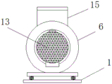
FIG. 1 is a schematic view of the overall structure of the present invention;
FIG. 2 is a schematic view of the overall left-side view structure of the present invention;
fig. 3 is an enlarged schematic view of a portion a in fig. 1 according to the present invention.
In the figure: 1. a base plate; 2. a spring; 3. a support; 4. a motor; 5. a first rotating shaft; 6. a fan pump body; 7. a blade; 8. a first bolt; 9. a second rotating shaft; 10. a brush; 11. a second bolt; 12. an air inlet cavity; 13. a first filter screen; 14. a heat generating plate; 15. an air outlet cavity; 16. a second filter screen; 17. a dust collection box; 18. drawing the box; 19. a chute.
Detailed Description
The technical solutions in the embodiments of the present invention will be described clearly and completely with reference to the accompanying drawings in the embodiments of the present invention, and it is obvious that the described embodiments are only some embodiments of the present invention, not all embodiments. Based on the embodiments in the present invention, all other embodiments obtained by a person skilled in the art without creative work belong to the protection scope of the present invention.
Referring to fig. 1-3, the present invention provides a technical solution: a centrifugal fan with an automatic dust removal function comprises a base plate 1 and a brush 10, wherein a spring 2 is installed on one side of the upper portion of the base plate 1, a support 3 is arranged on one side above the spring 2, a motor 4 is installed on the upper portion of the support 3, one side of the motor 4 is connected with a first rotating shaft 5, the other side of the first rotating shaft 5 is provided with a fan pump body 6, a blade 7 is fixed on the surface of the first rotating shaft 5, a first bolt 8 is installed at the end portion of the first rotating shaft 5, the other side of the first bolt 8 is connected with a second rotating shaft 9, the brush 10 is located on the other side of the second rotating shaft 9, a second bolt 11 is installed on one side of the fan pump body 6, an air inlet cavity 12 is formed in the other side of the second bolt 11, a first filter screen 13 is installed at one end of the air inlet cavity 12, a heating plate 14 is arranged above the air inlet cavity 12, an air outlet cavity 15 is, a dust collection box 17 is arranged below the air inlet chamber 12, a drawing box 18 is arranged on the surface of the dust collection box 17, and a sliding groove 19 is connected below the drawing box 18;
the bottom plate 1 and the support 3 form an elastic connection structure through the spring 2, the spring 2 is symmetrically distributed about the vertical center line of the bottom plate 1, a stable buffering effect can be achieved through the spring 2, vibration is prevented when the fan works, the motor 4 and the blades 7 form a rotating structure through the first rotating shaft 5, the rod diameter of the first rotating shaft 5 is larger than that of the second rotating shaft 9, and the blades 7 can be driven to rotate through the motor 4, so that air suction work is performed;
the first rotating shaft 5 and the second rotating shaft 9 form a detachable structure through the first bolt 8, the second rotating shaft 9 and the brush 10 form a welding integrated structure, the brush 10 is tightly attached to the first filter screen 13, and dust on the first filter screen 13 can be cleaned through the brush 10, so that the cleanliness of the device can be ensured, and the working effect of the fan is prevented from being influenced by excessive dust accumulation;
the fan pump body 6 passes through second bolt 11 and constitutes detachable construction between the air inlet chamber 12, and the number that sets up of the board 14 that generates heat is three, through the board 14 that generates heat, can heat gas, thereby prevent that gas too moist can cause the inside rusty phenomenon of device, take out box 18 and pass through to constitute the pull structure between spout 19 and the dust collection box 17, and spout 19 is symmetric distribution about the vertical central line of dust collection box 17, through spout 19, can clear up the dirt bits of collecting in taking out box 18.
The working principle is as follows: the motor 4 can rotate through the structure between the first rotating shaft 5 and the blade 7, firstly, the blade 7 is driven to rotate through the motor 4, so as to perform air suction operation, the first rotating shaft 5 can be detached from the second rotating shaft 9 through the first bolt 8, the second rotating shaft 9 and the brush 10 are welded into a whole, the brush 10 and the first filter screen 13 are tightly attached, at the moment, dust on the first filter screen 13 is cleaned through the brush 10, so that the cleanliness of the device can be ensured, the working effect of the fan is prevented from being influenced by excessive dust accumulation, the pumping box 18 can be pulled and pulled through the sliding groove 19 and the dust collection box 17, then, the dust collected in the pumping box 18 can be cleaned through the sliding groove 19, the fan pump body 6 can be detached from the air inlet cavity 12 through the second bolt 11, and the heating plate 14 is connected with the air inlet cavity 12, at this moment, the heating plate 14 is used for heating gas, so that the phenomenon that the gas is too wet and rusts inside the device is avoided, the bottom plate 1 is connected with the support 3 through the spring 2, and finally, the spring 2 can play a role in stabilizing and buffering, so that the fan is prevented from vibrating during working.
Although embodiments of the present invention have been shown and described, it will be appreciated by those skilled in the art that changes, modifications, substitutions and alterations can be made in these embodiments without departing from the principles and spirit of the invention, the scope of which is defined in the appended claims and their equivalents.
Claims (6)
1. The utility model provides a centrifugal fan with automatic dust removal function, includes bottom plate (1) and brush (10), its characterized in that: the improved fan is characterized in that a spring (2) is installed on one side of the upper portion of the base plate (1), a support (3) is arranged on one side of the upper portion of the spring (2), a motor (4) is installed on the upper portion of the support (3), one side of the motor (4) is connected with a first rotating shaft (5), a fan pump body (6) is arranged on the other side of the first rotating shaft (5), blades (7) are fixed on the surface of the first rotating shaft (5), a first bolt (8) is installed at the end portion of the first rotating shaft (5), the other side of the first bolt (8) is connected with a second rotating shaft (9), a brush (10) is located on the other side of the second rotating shaft (9), a second bolt (11) is installed on one side of the fan pump body (6), an air inlet cavity (12) is arranged on the other side of the second bolt (11), a first filter screen (, and the top of the air inlet chamber (12) is provided with a heating plate (14), the top of the fan pump body (6) is provided with an air outlet chamber (15), a second filter screen (16) is arranged above the air outlet chamber (15), the lower part of the air inlet chamber (12) is provided with a dust collection box (17), the surface of the dust collection box (17) is provided with a drawing box (18), and the lower part of the drawing box (18) is connected with a sliding groove (19).
2. The centrifugal fan with automatic dust removing function according to claim 1, characterized in that: the bottom plate (1) is in an elastic connection structure with the support (3) through the springs (2), and the springs (2) are symmetrically distributed about the vertical center line of the bottom plate (1).
3. The centrifugal fan with automatic dust removing function according to claim 1, characterized in that: the motor (4) forms a rotating structure through the first rotating shaft (5) and the blades (7), and the rod diameter of the first rotating shaft (5) is larger than that of the second rotating shaft (9).
4. The centrifugal fan with automatic dust removing function according to claim 1, characterized in that: first pivot (5) constitute detachable construction through between first bolt (8) and second pivot (9), and constitute welding integrated structure between second pivot (9) and brush (10) to closely laminate between brush (10) and first filter screen (13).
5. The centrifugal fan with automatic dust removing function according to claim 1, characterized in that: the fan pump body (6) forms a detachable structure through the second bolt (11) and the air inlet cavity (12), and the number of the heating plates (14) is three.
6. The centrifugal fan with automatic dust removing function according to claim 1, characterized in that: the drawer box (18) forms a drawing structure with the dust collection box (17) through the sliding groove (19), and the sliding groove (19) is symmetrically distributed about the vertical center line of the dust collection box (17).
Priority Applications (1)
| Application Number | Priority Date | Filing Date | Title |
|---|---|---|---|
| CN202021443438.4U CN213419412U (en) | 2020-07-21 | 2020-07-21 | Centrifugal fan with automatic dust removal function |
Applications Claiming Priority (1)
| Application Number | Priority Date | Filing Date | Title |
|---|---|---|---|
| CN202021443438.4U CN213419412U (en) | 2020-07-21 | 2020-07-21 | Centrifugal fan with automatic dust removal function |
Publications (1)
| Publication Number | Publication Date |
|---|---|
| CN213419412U true CN213419412U (en) | 2021-06-11 |
Family
ID=76254445
Family Applications (1)
| Application Number | Title | Priority Date | Filing Date |
|---|---|---|---|
| CN202021443438.4U Active CN213419412U (en) | 2020-07-21 | 2020-07-21 | Centrifugal fan with automatic dust removal function |
Country Status (1)
| Country | Link |
|---|---|
| CN (1) | CN213419412U (en) |
Cited By (2)
| Publication number | Priority date | Publication date | Assignee | Title |
|---|---|---|---|---|
| CN116696799A (en) * | 2023-07-25 | 2023-09-05 | 杭州紫光风机有限公司 | Centrifugal fan with airflow self-dedusting function |
| CN117231569A (en) * | 2023-11-09 | 2023-12-15 | 上海嵘熵动力科技有限公司 | Air suspension centrifugal fan with dust removal function |
-
2020
- 2020-07-21 CN CN202021443438.4U patent/CN213419412U/en active Active
Cited By (4)
| Publication number | Priority date | Publication date | Assignee | Title |
|---|---|---|---|---|
| CN116696799A (en) * | 2023-07-25 | 2023-09-05 | 杭州紫光风机有限公司 | Centrifugal fan with airflow self-dedusting function |
| CN116696799B (en) * | 2023-07-25 | 2024-04-26 | 王俊荣 | Centrifugal fan with airflow self-dedusting function |
| CN117231569A (en) * | 2023-11-09 | 2023-12-15 | 上海嵘熵动力科技有限公司 | Air suspension centrifugal fan with dust removal function |
| CN117231569B (en) * | 2023-11-09 | 2024-01-26 | 上海嵘熵动力科技有限公司 | Air suspension centrifugal fan with dust removal function |
Similar Documents
| Publication | Publication Date | Title |
|---|---|---|
| CN213419412U (en) | Centrifugal fan with automatic dust removal function | |
| CN207736017U (en) | Cycle dry type polishing centring system in a kind of | |
| CN115163268A (en) | Water-cooling silencer of diesel generating set | |
| CN211059038U (en) | Centrifugal fire-fighting smoke exhaust fan | |
| CN105003927B (en) | A kind of tail recuperation of heat dedusting integral type coal-burning boiler | |
| CN207546099U (en) | A kind of wind curtain type air purifier | |
| CN206700981U (en) | A kind of intelligent Environmental-protecting dust-removing device | |
| CN205208761U (en) | Mill uses high -power air purification device | |
| CN105020727A (en) | Tail heat utilization and dust removal integrated coal fired boiler | |
| CN210565318U (en) | Novel fan blade for centrifugal fan | |
| CN207069832U (en) | A kind of efficiently cyclone filter formula high-rating generator carbon dust absorption plant | |
| CN208244373U (en) | A kind of pulse filter cylinder cleaner | |
| CN210066024U (en) | Dust collector of weaving machine | |
| CN208493541U (en) | A kind of efficient cyclone dust-extraction unit | |
| CN209221775U (en) | A kind of portable water power fluting deduster | |
| CN202538554U (en) | Dust collector | |
| CN112933833A (en) | Sack cleaner removes dust heat sink in advance | |
| CN202418028U (en) | Novel backward abrasion-resistant fan impeller of road sweeper | |
| CN219754854U (en) | High-efficiency energy-saving environment-friendly treatment centrifugal fan | |
| CN212928267U (en) | Draught fan dust exhaust device with accelerated ventilation | |
| CN211009099U (en) | Silencing mechanism for roots fan cooling system | |
| CN219206729U (en) | Dust collecting device and robot cleaning system | |
| CN216361065U (en) | High-efficiency energy-saving steam-electricity dual-drive induced draft fan assembly | |
| CN204829971U (en) | Tail heat recovery dust removal integral type coal fired boiler | |
| CN215687417U (en) | Suction head of handheld dust collector |
Legal Events
| Date | Code | Title | Description |
|---|---|---|---|
| GR01 | Patent grant | ||
| GR01 | Patent grant |