CN213418047U - Urban underground sewage pipeline cleaning equipment - Google Patents
Urban underground sewage pipeline cleaning equipment Download PDFInfo
- Publication number
- CN213418047U CN213418047U CN202021975053.2U CN202021975053U CN213418047U CN 213418047 U CN213418047 U CN 213418047U CN 202021975053 U CN202021975053 U CN 202021975053U CN 213418047 U CN213418047 U CN 213418047U
- Authority
- CN
- China
- Prior art keywords
- rotating shaft
- gear
- terminal surface
- rotating
- cleaning
- Prior art date
- Legal status (The legal status is an assumption and is not a legal conclusion. Google has not performed a legal analysis and makes no representation as to the accuracy of the status listed.)
- Active
Links
Images



Landscapes
- Cleaning In General (AREA)
Abstract
The utility model relates to a city underground sewer line clean-up equipment, it includes the base, and the lower terminal surface of base is provided with the universal wheel, is provided with the cleaning box on the base, all rotates on the lower terminal surface of cleaning box and the adjacent terminal surface to be connected with a plurality of desilting pieces, is provided with drive assembly in the cleaning box, and a plurality of desilting pieces of drive assembly drive rotate together. Through setting up desilting spare and drive assembly, the desilting spare of terminal surface clears up deposit and silt on the sewage pipe lower extreme inner wall under the control drive assembly drive cleaning case, and the desilting spare on the adjacent terminal surface of drive cleaning case clears up deposit and silt on the sewage pipe inside wall simultaneously, has reduced the time that the clearance sewage pipe consumed, has improved work efficiency.
Description
Technical Field
The application relates to the field of pipeline cleaning technology, in particular to urban underground sewage pipeline cleaning equipment.
Background
The main function of the urban underground sewage pipeline is to collect sewage in the area along the pipeline and convey the sewage to a downstream main pipe or a sewage treatment plant for sewage treatment. The sewage pipeline can have some deposit debris after long-time use, and when deposit debris accumulated excessively, the deposit debris can lead to the sewage pipeline jam, influences people's daily life, adopts sewage pipeline cleaning device to clear up the sewage pipeline usually.
For example, the patent publication No. CN208105464U Chinese utility model discloses a cleaning device for urban sewage pipelines, which comprises a support plate, a pump body, a sludge box, a drawable box body, a B rotating column, a brush body and a motor, wherein the pump body is arranged on the upper part of the support plate, the pump body is connected with the lower end of a sludge pipe, the upper end of the sludge pipe is connected with the sludge box, the drawable box body is arranged in the sludge box, the drawable box body is communicated with the sludge pipe, a closed card is movably arranged at the communication position of the drawable box body and the sludge pipe, an A rotating column is arranged at the lower part of the supporting plate, the lower end of the A rotating column is connected with a B rotating column through threads, a brush body is arranged on the B rotating column, the A rotating column and the B rotating column are hollow, the sludge pipe is communicated with the A rotating column and the B rotating column, a motor is arranged on the supporting plate, a shaft of the motor penetrates through the supporting plate to be connected with an A gear at the lower part of the supporting plate, the A gear is meshed with the B gear, and the B gear is sleeved on the.
With the cleaning device, the inventor finds that the time for cleaning the pipeline is long and needs to be improved.
SUMMERY OF THE UTILITY MODEL
In order to solve the problem that the time consumed for cleaning a pipeline is long, the application provides urban underground sewage pipeline cleaning equipment.
The utility model provides a city underground sewage pipeline cleaning equipment adopts following technical scheme:
the utility model provides a city underground sewer line clean-up equipment, includes the base, the lower terminal surface of base is provided with the universal wheel, be provided with the cleaning box on the base, all rotate on the lower terminal surface of cleaning box and the adjacent terminal surface and be connected with a plurality of desilting pieces, be provided with drive assembly in the cleaning box, drive assembly drives a plurality of desilting piece rotates together.
Through adopting above-mentioned technical scheme, when clearing up the sewer line, control transmission assembly drive desilting piece rotates, the desilting piece of terminal surface clears up deposit and silt on the sewer line lower extreme inner wall under the cleaning box, the desilting piece on the adjacent terminal surface of drive cleaning box clears up deposit and silt on the sewer line inside wall simultaneously, for clearing up another inner wall of sewer line after clearing up one of them inner wall of sewer line, the time that the clearance sewer line consumed has been reduced, and the work efficiency is improved.
Optionally, an accommodating cavity is arranged in the cleaning box; the transmission assembly comprises a first rotating shaft, a first gear, a second rotating shaft, a second gear, a first bevel gear, a third rotating shaft and a second bevel gear, the first rotating shaft is rotatably connected to the cleaning box, the rotating axis of the first rotating shaft is vertically arranged, the first gear is coaxially fixed on the first rotating shaft, a driving piece is arranged on the base, and the driving piece drives the first rotating shaft to rotate; the second rotating shaft is rotatably connected to the cleaning box, the rotating axis of the second rotating shaft is parallel to the rotating axis of the first rotating shaft, the second gear is coaxially fixed on the second rotating shaft, the second gear is meshed with the first gear, and the first bevel gear is coaxially fixed on the second rotating shaft; the third rotating shaft penetrates through the inner side wall of the accommodating cavity and is rotatably connected to the cleaning box, the rotating axis of the third rotating shaft is perpendicular to the rotating axis of the second rotating shaft, the second bevel gear is coaxially fixed on the third rotating shaft and is positioned in the accommodating cavity, and the second bevel gear is meshed with the first bevel gear; one of them is located terminal surface under the clearance case the desilting piece set up in first pivot is along its axis of rotation's lower extreme, and another is located terminal surface under the clearance case the desilting piece set up in the second pivot is along its axis of rotation's lower extreme, the adjacent terminal surface of clearance case the desilting piece set up in the third pivot is kept away from hold on the tip in chamber.
By adopting the technical scheme, the driving part is controlled to drive the first rotating shaft to rotate, the first rotating shaft drives the first gear to rotate, the first gear drives the second rotating shaft to rotate through meshing with the second gear, the second rotating shaft drives the desilting part thereon to rotate so as to clean sediments and silt on the inner wall of the lower end of the sewage pipeline, the second rotating shaft drives the first bevel gear to rotate, the first bevel gear drives the second bevel gear to rotate through meshing with the second bevel gear, the second bevel gear drives the third rotating shaft to rotate, the third rotating shaft drives the desilting part thereon to rotate so as to clean sediments and silt on the corresponding inner side wall of the sewage pipeline, and the cleaning parts on the lower end surface and the adjacent end surface of the cleaning box can be driven to simultaneously clean the corresponding inner wall of the sewage pipeline through the mutual matching of the first rotating shaft, the first gear, the second rotating shaft, the second gear, the first bevel gear, the third rotating shaft and the second bevel gear, the desilting piece can be operated and rotated more conveniently; through driving desilting piece simultaneously and clearing up sewage pipe together for clear up sewage pipe is more high-efficient, has reduced the time that the driving piece used, thereby has reduced the consumption of energy, has energy-conserving effect.
Optionally, a third gear is coaxially fixed on the third rotating shaft, the third gear is located on one side of the second bevel gear, which is far away from the first bevel gear, an end surface of the third gear, which is far away from the second bevel gear, abuts against a corresponding inner wall of the accommodating cavity to limit the third rotating shaft, a plurality of fourth rotating shafts are rotatably connected to the cleaning box, rotating axes of the plurality of fourth rotating shafts are all arranged in parallel to a rotating axis of the third rotating shaft, and the plurality of fourth rotating shafts are circumferentially distributed along the rotating axis of the third rotating shaft; every all coaxial fixed with fourth gear in the fourth pivot, it is a plurality of the fourth gear all with the third gear meshing, part are located the adjacent terminal surface of clearance case the desilting piece set up in the fourth pivot is kept away from hold on the tip in chamber.
Through adopting above-mentioned technical scheme, the third pivot rotates and drives third gear revolve, and the third gear drives fourth gear revolve through meshing with the fourth gear, and the fourth gear drives the fourth pivot and rotates, thereby the fourth pivot drives it and clears up silt piece rotation and clear up deposit and silt on the corresponding inside wall of sewer line, has increased the area that the clearance case can clear up, has reduced the time that the clearance sewage passageway consumes, has improved work efficiency.
Optionally, a supporting plate is arranged on the inner wall of the accommodating cavity, the third rotating shaft penetrates through the supporting plate, and each fourth rotating shaft is located at the end part of the accommodating cavity and is rotatably connected to the supporting plate.
By adopting the technical scheme, the supporting plate is arranged to support the third rotating shaft, so that the stability of the second bevel gear and the third rotating shaft during rotation is improved, and the pressure exerted by the second bevel gear on the first bevel gear is reduced, thereby reducing the abrasion between the second bevel gear and the first bevel gear during rotation and enabling the bevel gears to be more durable; meanwhile, the stability of the fourth rotating shaft in rotation is improved, and the abrasion of the rotating connection position of the fourth rotating shaft and the cleaning box is reduced, so that the fourth rotating shaft is more durable.
Optionally, each dredging piece all includes connecting block and threaded connection in brush head on the connecting block, one of them is located terminal surface under the clearance case the connecting block is fixed in the first pivot, another is located terminal surface under the clearance case the connecting block is fixed in the second pivot, one of them is located the adjacent terminal surface of clearance case the connecting block is fixed in the third pivot, all the other are located the adjacent terminal surface of clearance case the connecting block is fixed in the fourth pivot.
By adopting the technical scheme, the connecting blocks and the brush heads are arranged, when the brush heads are used for a long time, the brush heads are seriously worn to cause damage, the damaged brush heads can be taken down from the corresponding connecting blocks by twisting the brush heads, and then the new brush heads are aligned to the connecting blocks and twisted to realize the installation of the new brush heads on the connecting blocks, so that the brush heads are more convenient to install and replace; when the cleaning box is used up, the brush head on the dredging part on the second rotating shaft can be taken down, so that the damage caused by the friction between the dredging part on the second rotating shaft and the ground in the moving process of the cleaning box is reduced.
Optionally, every brush head all include with correspond connecting portion of connecting block threaded connection with set up in clearance portion on the connecting portion, clearance portion is located connecting portion are kept away from correspondingly one side of connecting block, clearance portion is towards keeping away from the connecting block direction is the setting of gradually expanding.
Through adopting above-mentioned technical scheme, when the desilting piece rotates, contradict the inner wall of sewer line with the brush head on the desilting piece, the tip that the connecting block was kept away from to the clearance portion is formed with most advanced, thereby the most advanced card in the clearance portion is gone into between deposit or silt and the sewer line inner wall and is scraped deposit or silt and get off in order to clear up the sewer line when rotating for deposit or silt on the desilting piece clearance sewer line inner wall are more convenient.
Optionally, each cleaning part is far away from the end face corresponding to the connecting block, mounting grooves are formed in the end face, and bristles are arranged in the mounting grooves.
Through adopting above-mentioned technical scheme, scrape the back of getting off when clearance portion with deposit or silt on the sewage pipe inner wall, the brush hair on the clearance portion is further cleared up the inner wall of sewage pipe after scraping for deposit or silt on the sewage pipe inner wall remain still less, make the clearance effect of desilting piece better.
Optionally, a water tank is further arranged on the base, a water pump is further arranged on the base, a water pumping end of the water pump is communicated with the inside of the water tank and is close to the bottom of the inside of the water tank, and a water pipe is arranged at a water outlet end of the water pump.
Through adopting above-mentioned technical scheme, after dredging piece cleared up sewage conduit's inner wall, partial deposit and silt adhesion are on brush head and sewage conduit's inner wall, aim at the place of deposit and silt adhesion through handheld water pipe, the control water pump is drawn water from the water tank, water gets into in the water pipe through the play water end of water pump, and spout from the water pipe exit, wash deposit and silt from the inner wall of brush head or sewage conduit, the condition that brush head cleaning performance worsens at the cleaning process has been reduced, and make sewage conduit's cleaning performance better.
In summary, the present application includes at least one of the following beneficial technical effects:
by arranging the dredging part and the transmission assembly, the transmission assembly is controlled to drive the dredging part on the lower end surface of the cleaning box to clean sediment and sludge on the inner wall of the lower end of the sewage pipeline, and simultaneously the dredging part on the adjacent end surface of the cleaning box is driven to clean the sediment and the sludge on the inner wall of the sewage pipeline, so that the time consumed for cleaning the sewage pipeline is reduced, and the working efficiency is improved;
the first rotating shaft, the first gear, the second rotating shaft, the second gear, the first bevel gear, the third rotating shaft and the second bevel gear are arranged, and are matched with each other to drive the dredging parts on the lower end face and the adjacent end face of the cleaning box to clean the corresponding inner walls of the sewage pipeline simultaneously, so that the operation of the dredging parts to rotate simultaneously is more convenient;
through setting up fourth pivot and fourth gear, increased the area that the clearance case can clear up, reduced the time that the clearance sewage passageway consumed, improved work efficiency.
Drawings
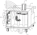
FIG. 1 is an overall view of the present embodiment;
FIG. 2 is a sectional view of the cleaning box of the present embodiment, mainly showing the structure of the transmission assembly;
FIG. 3 is a sectional view of the cleaning box of the present embodiment, mainly illustrating the structure of the fourth shaft;
FIG. 4 is a partial exploded view of the present embodiment, mainly showing the structure of the dredging member;
FIG. 5 is a sectional view of the water tank of the present embodiment, mainly illustrating the structure of the water storage chamber;
fig. 6 is an enlarged view of portion a of fig. 5, showing primarily the configuration of the rings and hooks.
Description of reference numerals: 1. a base; 11. a universal wheel; 12. a handle; 13. a through hole; 2. a water tank; 21. a water storage cavity; 22. a circular ring; 3. cleaning the box; 31. an accommodating chamber; 32. a drive member; 4. a support plate; 5. a transmission assembly; 51. a first rotating shaft; 52. a first gear; 53. a second rotating shaft; 54. a second gear; 55. a first bevel gear; 56. a third rotating shaft; 561. a third gear; 57. a second bevel gear; 6. a fourth rotating shaft; 61. a fourth gear; 7. a dredging member; 71. connecting blocks; 711. a threaded hole; 72. a brush head; 721. a connecting portion; 722. a cleaning part; 7221. mounting grooves; 8. brushing; 9. a water pump; 10. a water pipe; 101. and (4) hanging hooks.
Detailed Description
The present application is described in further detail below with reference to figures 1-6.
The embodiment of the application discloses urban underground sewage pipeline cleaning equipment. Referring to fig. 1, urban underground sewage pipeline cleaning equipment includes base 1, and the lower terminal surface of base 1 is the rectangle setting, and the lower terminal surface of base 1 rotates and is connected with four universal wheels 11, and four universal wheels 11 are located four dog-ear departments of base 1 respectively. The upper end face of base 1 is fixed with cleaning box 3 and water tank 2, and water tank 2 is located cleaning box 3 and is close to one side of base 1 along the horizontal direction, and base 1 still is fixed with handle 12 on keeping away from the terminal surface of water tank 2 along the horizontal direction.
Referring to fig. 2, be equipped with in the cleaning box 3 and hold chamber 31, be fixed with backup pad 4 on holding the inner wall in chamber 31, backup pad 4 is vertical setting, and the laminating of the periphery wall of backup pad 4 holds the inner wall setting in chamber 31. The accommodating cavity 31 is further provided with a transmission assembly 5, and the transmission assembly 5 comprises a first rotating shaft 51, a first gear 52, a second rotating shaft 53, a second gear 54, a first bevel gear 55, a third rotating shaft 56 and a second bevel gear 57. First pivot 51 rotates to be connected on cleaning box 3, and the axis of rotation of first pivot 51 is vertical setting, and first pivot 51 wears to establish the corresponding inner wall setting that holds chamber 31 respectively along its axis of rotation's relative both ends.
Referring to fig. 2, a driving member 32 is fixed on an outer side wall of the cleaning box 3, the driving member 32 is located above the first rotating shaft 51, in this embodiment, the driving member 32 is a motor, an output shaft of the driving member 32 is disposed toward the first rotating shaft 51 and fixedly connected with a corresponding end of the first rotating shaft 51 along a rotating axis thereof, and the driving member 32 drives the first rotating shaft 51 to rotate. The first gear 52 is coaxially fixed on the first rotating shaft 51, and the first rotating shaft 51 drives the first gear 52 to rotate.
Referring to fig. 2, the second rotating shaft 53 is rotatably connected to the cleaning box 3, the second rotating shaft 53 and the first rotating shaft 51 are both located on the same side of the supporting plate 4, the rotating axis of the second rotating shaft 53 is parallel to the rotating axis of the first rotating shaft 51, and the second rotating shaft 53 is respectively arranged on the corresponding inner walls of the accommodating cavity 31 along the opposite two ends of the rotating axis. The second gear 54 is coaxially fixed on the second rotating shaft 53, the position of the second gear 54 is arranged corresponding to the position of the first gear 52, the second gear 54 and the first gear 52 are arranged in a mutually meshed manner, and the second rotating shaft 53 is rotatably connected to the cleaning box 3 through the matching of the second gear 54 and the first gear 52.
Referring to fig. 2, the first bevel gear 55 is coaxially fixed on the second rotating shaft 53, the first bevel gear 55 is located below the second gear 54, the first bevel gear 55 and the second gear 54 are arranged at an interval, and a small end of the first bevel gear 55 faces upward. The radial distance between the end of the tooth on the first gear 52 away from the rotation axis of the first rotating shaft 51 and the outer side wall of the first rotating shaft 51 is greater than the radial distance between the large end of the first bevel gear 55 and the outer side wall of the second rotating shaft 53.
Referring to fig. 2, the third rotating shaft 56 is located on one side of the second rotating shaft 53 far away from the first rotating shaft 51, the third rotating shaft 56 is horizontally arranged, the end portion of the third rotating shaft 56 far away from the second rotating shaft 53 penetrates through the inner side wall of the accommodating cavity 31 far away from the first rotating shaft 51, the end portion of the third rotating shaft 56 close to the second rotating shaft 53 penetrates through the supporting plate 4, the third rotating shaft 56 is rotatably connected in the cleaning box 3, and the rotating axis of the third rotating shaft 56 is perpendicular to the rotating axis of the second rotating shaft 53.
Referring to fig. 2, the second bevel gear 57 is coaxially fixed on the third rotating shaft 56, the second bevel gear 57 is located in the accommodating cavity 31, the second bevel gear 57 is located at the end of the third rotating shaft 56 close to the second rotating shaft 53, the small end of the second bevel gear 57 is located close to the second rotating shaft 53, the second bevel gear 57 and the first bevel gear 55 are arranged in a meshed manner, and the third rotating shaft 56 is rotatably connected to the cleaning box 3 through the matching of the second bevel gear 57 and the first bevel gear 55.
Referring to fig. 2, a third gear 561 is further coaxially fixed on the third rotating shaft 56, the third gear 561 is located on one side of the second bevel gear 57 away from the first bevel gear 55, the third gear 561 is located on one side of the support plate 4 away from the second bevel gear 57, and an end surface of the third gear 561 away from the second bevel gear 57 collides with a corresponding inner wall of the accommodating cavity 31 to realize the limiting of the third rotating shaft 56.
Referring to fig. 2 and 3, cleaning box 3 is last still to rotate and to be connected with a plurality of fourth pivot 6, a plurality of fourth pivot 6 all lie in the same one side setting that holds chamber 31 with third pivot 56, a plurality of fourth pivot 6 are circumference evenly distributed along the axis of rotation of third pivot 56, the axis of rotation of a plurality of fourth pivot 6 all is on a parallel with the axis of rotation setting of third pivot 56, and every fourth pivot 6 lies in the tip that holds chamber 31 and all wears to establish backup pad 4 and rotate with backup pad 4 and be connected the setting.
Referring to fig. 2 and 3, a fourth gear 61 is coaxially fixed on each fourth rotating shaft 6, each fourth gear 61 is located on one side of the support plate 4 away from the second rotating shaft 53, and the end surface of each fourth gear 61 away from the support plate 4 is abutted against the corresponding inner wall of the accommodating cavity 31. Each of the fourth gears 61 is engaged with the third gear 561, and the diameter of each of the fourth gears 61 is set smaller than the diameter of the third gear 561. Each fourth rotating shaft 6 is connected to the cleaning box 3 through the cooperation of the fourth gear 61 and the third gear 561.
Referring to fig. 3, the lower end of the first rotating shaft 51 along the rotating axis thereof, the lower end of the second rotating shaft 53 along the rotating axis thereof, the end of the third rotating shaft 56 far away from the accommodating cavity 31 and the ends of the fourth rotating shafts 6 far away from the accommodating cavity 31 are all fixed with the dredging member 7, and the dredging member 7 is positioned outside the cleaning box 3. The dredging member 7 fixed to the lower end of the first rotating shaft 51 along its rotational axis and the dredging member 7 fixed to the lower end of the second rotating shaft 53 along its rotational axis are both located on the lower end face of the cleaning tank 3, and the dredging member 7 fixed to the end of the third rotating shaft 56 remote from the accommodating chamber 31 and the dredging member 7 fixed to the end of the fourth rotating shaft 6 remote from the accommodating chamber 31 are both located on the end face of the cleaning tank 3 adjacent to the lower end face thereof.
Referring to fig. 3, two through holes (not shown) are formed in the base 1, the positions of the two through holes are respectively corresponding to the dredging part 7 on the first rotating shaft 51 and the dredging part 7 on the second rotating shaft 53, one of the through holes is used for the dredging part 7 on the first rotating shaft 51 to penetrate, and the other through hole is used for the dredging part 7 on the second rotating shaft 53 to penetrate.
Referring to fig. 3, the dredging member 7 on the first rotating shaft 51 is rotatably connected to the cleaning box 3 through the driving member 32 and the matching of the first rotating shaft 51 and the cleaning box 3, the dredging member 7 on the second rotating shaft 53 is rotatably connected to the cleaning box 3 through the matching of the second rotating shaft 53 and the cleaning box 3, the dredging member 7 on the third rotating shaft 56 is rotatably connected to the cleaning box 3 through the matching of the third rotating shaft 56 and the cleaning box 3, the dredging member 7 on the fourth rotating shaft 6 is rotatably connected to the cleaning box 3 through the matching of the fourth rotating shaft 6 and the cleaning box 3, and the first rotating shaft 51, the second rotating shaft 53, the third rotating shaft 56 and the fourth rotating shaft 6 drive the dredging members 7 thereon to rotate together.
Referring to fig. 3 and 4, each dredging member 7 comprises a connecting block 71 and a brush head 72, wherein one connecting block 71 located on the lower end surface of the cleaning box 3 is fixedly connected with the lower end of the second rotating shaft 53, and the other connecting block 71 located on the lower end surface of the cleaning box 3 is fixedly connected with the lower end of the first rotating shaft 51. One of the connecting blocks 71 on the end face of the cleaning box 3 adjacent to the lower end face thereof is fixed to the corresponding end portion of the third rotating shaft 56, and the other connecting blocks 71 on the end face of the cleaning box 3 adjacent to the lower end face thereof are respectively fixed to the corresponding end portions of the corresponding fourth rotating shafts 6.
Referring to fig. 3 and 4, a threaded hole 711 is formed in an end surface of each connecting block 71 away from the accommodating cavity 31, a screwing direction of threads on the threaded hole 711 of the connecting block 71 on the second rotating shaft 53 is opposite to a rotating direction of the second rotating shaft 53, a screwing direction of threads on the threaded hole 711 of the connecting block 71 on the third rotating shaft 56 is opposite to a rotating direction of the third rotating shaft 56, and a screwing direction of threads on the threaded hole 711 of the connecting block 71 on each fourth rotating shaft 6 is opposite to a rotating direction of the corresponding fourth rotating shaft 6.
Referring to fig. 4, each brush head 72 includes a connecting portion 721 and a cleaning portion 722, an external thread is provided on an outer side wall of the connecting portion 721, and the connecting portion 721 is threadedly coupled to the threaded hole 711 of the corresponding connecting block 71. The cleaning portion 722 is fixed on a side of the corresponding connecting portion 721 away from the corresponding connecting block 71, in actual use, the cleaning portion 722 is integrally disposed with the corresponding connecting portion 721, and the cleaning portion 722 is gradually enlarged toward a direction away from the corresponding connecting block 71. The end face, away from the connecting block 71, of the cleaning portion 722 is provided with a mounting groove 7221, bristles 8 are fixedly bonded to the inner wall of the mounting groove 7221, and the end portion, away from the connecting portion 721, of each bristle 8 is flush with the end portion, away from the connecting portion 721, of the cleaning portion 722.
In actual use, the brush head 72 on the dredging member 7 is far away from the end of the connecting block 71 and is abutted against the corresponding inner wall of the sewage pipeline, the end of the cleaning part 722 far away from the connecting block 71 is clamped between the sediment or the sludge and the inner wall of the sewage pipeline when rotating along with the cleaning part 722, so that the sediment or the sludge is scraped to clean the sewage pipeline, the inner wall of the scraped sewage pipeline is brushed by the brush bristles 8 on the cleaning part 722 to achieve the further cleaning effect, the sediment or the sludge on the inner wall of the sewage pipeline can be cleaned by the dredging member 7 more conveniently, and the cleaning effect is better.
Referring to fig. 5 and 6, a water storage cavity 21 is arranged in the water tank 2, and a circular ring 22 is fixed on the outer side wall of the water tank 2, and the circular ring 22 is horizontally arranged. The base 1 up end still is fixed with water pump 9, and the end of drawing water on the water pump 9 communicates with water storage chamber 21, and the end of drawing water on the water pump 9 is close to the bottom setting in water storage chamber 21, and play water end fixedly connected with water pipe 10 on the water pump 9, in this embodiment, water pipe 10 is the flexible pipe, and the lateral wall of water pipe 10 is fixed with couple 101, and in the in-service use, the ring 22 that water tank 2 was worn to establish to couple 101 on the water pipe 10 realizes accomodating of water pipe 10.
The implementation principle of the urban underground sewage pipeline cleaning equipment in the embodiment of the application is as follows:
when cleaning the sewage pipeline, the driving member 32 is controlled to drive the first rotating shaft 51 to rotate, the first rotating shaft 51 drives the first gear 52 to rotate, the first gear 52 drives the second rotating shaft 53 to rotate through meshing with the second rotating shaft 53, the second rotating shaft 53 drives the first bevel gear 55 to rotate, the first bevel gear 55 drives the second bevel gear 57 and the third rotating shaft 56 to rotate through meshing with the second bevel gear 57, the third rotating shaft 56 drives the third gear 561 to rotate, the third gear 561 drives the fourth gears 61 to rotate through meshing with the fourth gears 61 and the fourth rotating shafts 6, so that the dredging members 7 on the first rotating shaft 51, the second rotating shaft 53, the third rotating shaft 56 and the fourth rotating shafts 6 rotate together, the dredging members 7 on the lower end face of the cleaning box 3 clean sediment and sludge on the inner wall of the lower end of the sewage pipeline, and simultaneously the cleaning members 7 on the end face of the cleaning box 3 adjacent to the lower end face clean the sediment and sludge on the inner side wall of the sewage pipeline Compared with the method that the inner wall of the sewage pipeline is cleaned after one inner wall of the sewage pipeline is cleaned, the method reduces the time consumed by cleaning the sewage pipeline, improves the working efficiency, and reduces the time used by the transmission assembly 5, thereby reducing the energy consumed by the driving part 32 and having the effect of energy saving.
When piece 7 clearance sewer pipe inner wall, break away from couple 101 on the water pipe 10 and the ring 22 on the water tank 2, take off water pipe 10, aim at the sewer pipe inner wall that piece 7 or piece 7 cleared up through handheld water pipe 10 and wash, deposit and the silt that will desilting 7 scrape down wash down from desilting 7 and the sewer pipe inner wall of clearing up, the condition that piece 7 clearance effect worsened at clearance in-process has been reduced to the sediment or the silt of adhesion on the sewer pipe inner wall of clearing up has been reduced, make sewer pipe's clearance effect better.
The above embodiments are preferred embodiments of the present application, and the protection scope of the present application is not limited by the above embodiments, so: all equivalent changes made according to the structure, shape and principle of the present application shall be covered by the protection scope of the present application.
Claims (8)
1. The utility model provides an urban underground sewage pipeline cleaning equipment, includes base (1), the lower terminal surface of base (1) is provided with universal wheel (11), its characterized in that: be provided with clearance case (3) on base (1), all rotate on the lower terminal surface of clearance case (3) and the adjacent terminal surface and be connected with a plurality of desilting pieces (7), be provided with drive assembly (5) in clearance case (3), drive assembly (5) drive a plurality of desilting piece (7) rotate together.
2. The municipal underground sewer line cleaning apparatus of claim 1, wherein: an accommodating cavity (31) is arranged in the cleaning box (3);
the transmission assembly (5) comprises a first rotating shaft (51), a first gear (52), a second rotating shaft (53), a second gear (54), a first bevel gear (55), a third rotating shaft (56) and a second bevel gear (57), the first rotating shaft (51) is rotatably connected to the cleaning box (3), the rotating axis of the first rotating shaft (51) is vertically arranged, the first gear (52) is coaxially fixed on the first rotating shaft (51), a driving part (32) is arranged on the base (1), and the driving part (32) drives the first rotating shaft (51) to rotate;
the second rotating shaft (53) is rotatably connected to the cleaning box (3), the rotating axis of the second rotating shaft (53) is parallel to the rotating axis of the first rotating shaft (51), the second gear (54) is coaxially fixed on the second rotating shaft (53), the second gear (54) is meshed with the first gear (52), and the first bevel gear (55) is coaxially fixed on the second rotating shaft (53);
the third rotating shaft (56) penetrates through the inner side wall of the accommodating cavity (31) and is rotatably connected to the cleaning box (3), the rotating axis of the third rotating shaft (56) is perpendicular to the rotating axis of the second rotating shaft (53), the second bevel gear (57) is coaxially fixed on the third rotating shaft (56), the second bevel gear (57) is located in the accommodating cavity (31), and the second bevel gear (57) is meshed with the first bevel gear (55);
one of them is located terminal surface under clearance case (3) desilting piece (7) set up in first pivot (51) are along its axis of rotation's lower extreme, and another is located terminal surface under clearance case (3) desilting piece (7) set up in second pivot (53) are along its axis of rotation's lower extreme, the adjacent terminal surface of clearance case (3) desilting piece (7) set up in third pivot (56) are kept away from hold on the tip of chamber (31).
3. The municipal underground sewer cleaning apparatus according to claim 2, wherein: a third gear (561) is coaxially fixed on the third rotating shaft (56), the third gear (561) is located on one side, away from the first bevel gear (55), of the second bevel gear (57), the end face, away from the second bevel gear (57), of the third gear (561) abuts against the corresponding inner wall of the accommodating cavity (31) to limit the third rotating shaft (56), a plurality of fourth rotating shafts (6) are rotatably connected to the cleaning box (3), the rotating axes of the plurality of fourth rotating shafts (6) are all arranged in parallel to the rotating axis of the third rotating shaft (56), and the plurality of fourth rotating shafts (6) are circumferentially distributed along the rotating axis of the third rotating shaft (56);
a fourth gear (61) is coaxially fixed on each fourth rotating shaft (6), the fourth gears (61) are meshed with the third gear (561), and the part of the dredging piece (7) located on the adjacent end face of the cleaning box (3) is arranged on the end part, far away from the accommodating cavity (31), of the fourth rotating shaft (6).
4. The municipal underground sewer cleaning apparatus according to claim 3, wherein: the inner wall of the accommodating cavity (31) is provided with a supporting plate (4), the third rotating shaft (56) penetrates through the supporting plate (4), and each fourth rotating shaft (6) is located at the end part of the accommodating cavity (31) and is connected to the supporting plate (4) in a rotating mode.
5. The municipal underground sewer cleaning apparatus according to claim 3, wherein: every desilting piece (7) all include connecting block (71) and threaded connection in brush head (72) on connecting block (71), one of them is located terminal surface under cleaning box (3) connecting block (71) are fixed in on first pivot (51), and another is located terminal surface under cleaning box (3) connecting block (71) are fixed in on second pivot (53), and one of them is located the adjacent terminal surface of cleaning box (3) connecting block (71) are fixed in on third pivot (56), and the rest is located the adjacent terminal surface of cleaning box (3) connecting block (71) are fixed in on fourth pivot (6).
6. The municipal underground sewer cleaning apparatus according to claim 5, wherein: each brush head (72) comprises a connecting part (721) in threaded connection with the corresponding connecting block (71) and a cleaning part (722) arranged on the connecting part (721), the cleaning part (722) is positioned on one side, away from the corresponding connecting block (71), of the connecting part (721), and the cleaning part (722) is arranged in a gradually expanding manner in the direction away from the connecting block (71).
7. The municipal underground sewer cleaning apparatus according to claim 6, wherein: every clearance portion (722) are kept away from and are corresponded mounting groove (7221) have all been seted up on the terminal surface of connecting block (71), be provided with brush hair (8) in mounting groove (7221).
8. The municipal underground sewer line cleaning apparatus of claim 1, wherein: still be provided with water tank (2) on base (1), still be provided with water pump (9) on base (1), the end of drawing water of water pump (9) with the inside intercommunication of water tank (2) and be close to the inside bottom setting of water tank (2), the play water end of water pump (9) is provided with water pipe (10).
Priority Applications (1)
| Application Number | Priority Date | Filing Date | Title |
|---|---|---|---|
| CN202021975053.2U CN213418047U (en) | 2020-09-10 | 2020-09-10 | Urban underground sewage pipeline cleaning equipment |
Applications Claiming Priority (1)
| Application Number | Priority Date | Filing Date | Title |
|---|---|---|---|
| CN202021975053.2U CN213418047U (en) | 2020-09-10 | 2020-09-10 | Urban underground sewage pipeline cleaning equipment |
Publications (1)
| Publication Number | Publication Date |
|---|---|
| CN213418047U true CN213418047U (en) | 2021-06-11 |
Family
ID=76261178
Family Applications (1)
| Application Number | Title | Priority Date | Filing Date |
|---|---|---|---|
| CN202021975053.2U Active CN213418047U (en) | 2020-09-10 | 2020-09-10 | Urban underground sewage pipeline cleaning equipment |
Country Status (1)
| Country | Link |
|---|---|
| CN (1) | CN213418047U (en) |
-
2020
- 2020-09-10 CN CN202021975053.2U patent/CN213418047U/en active Active
Similar Documents
| Publication | Publication Date | Title |
|---|---|---|
| CN210676235U (en) | Gas transmission pipeline dredging device | |
| CN211447228U (en) | Equipment is prevented cutting to pieces and rubbing by dredging of town road pipeline inner wall | |
| CN116510397B (en) | Waste water treatment device for mine tailing sludge solidification technology | |
| CN211726813U (en) | Mechanical cleaning device for sludge on surface of pipeline | |
| CN215715945U (en) | Novel pipeline desilting mediation device | |
| CN213418047U (en) | Urban underground sewage pipeline cleaning equipment | |
| CN212121099U (en) | Municipal administration water supply and drainage pipeline exempts from to excavate inner wall belt cleaning device | |
| CN213358909U (en) | Dredging device for underground sewage pipeline | |
| CN214138889U (en) | Semi-automatic rust removing and cleaning device for ship and ocean engineering | |
| CN220266809U (en) | Pipeline dredging device for municipal drainage engineering | |
| CN215928825U (en) | Multifunctional water supply and drainage pipeline | |
| CN216175026U (en) | Underground pipeline maintenance cleaning device for municipal administration | |
| CN214235419U (en) | Device capable of removing calcium sulfate on inner wall of petroleum pipeline | |
| CN212926433U (en) | Dredging device for urban water supply and drainage | |
| CN213159704U (en) | Back-suction nozzle box convenient to dredge | |
| CN209901892U (en) | Petrochemical wastewater treatment machine | |
| CN210968227U (en) | Grinding machine for processing polyurethane coating sleeve | |
| CN216655646U (en) | A pipeline cleaning device for building plumbing | |
| CN217613131U (en) | Sewage sedimentation tank moss clearing device | |
| CN212733404U (en) | Pipeline flushing device | |
| CN213475447U (en) | Mud scraper for sewage treatment | |
| CN218025599U (en) | Landscape water ecological restoration system | |
| CN211563813U (en) | Valve cleaning device for valve production | |
| CN220312700U (en) | Protective cover for machine tool machining | |
| CN211191288U (en) | Pool wall cleaning device of secondary sedimentation pool |
Legal Events
| Date | Code | Title | Description |
|---|---|---|---|
| GR01 | Patent grant | ||
| GR01 | Patent grant |