CN213412796U - Automatic elastic part for injection mold - Google Patents
Automatic elastic part for injection mold Download PDFInfo
- Publication number
- CN213412796U CN213412796U CN202021551686.0U CN202021551686U CN213412796U CN 213412796 U CN213412796 U CN 213412796U CN 202021551686 U CN202021551686 U CN 202021551686U CN 213412796 U CN213412796 U CN 213412796U
- Authority
- CN
- China
- Prior art keywords
- injection mold
- bearing box
- sides
- push
- push rod
- Prior art date
- Legal status (The legal status is an assumption and is not a legal conclusion. Google has not performed a legal analysis and makes no representation as to the accuracy of the status listed.)
- Active
Links
Images

Landscapes
- Moulds For Moulding Plastics Or The Like (AREA)
Abstract
The utility model discloses an injection mold is with automatic bullet material accessory, including last mould and bed die, it is located the top of bed die to go up the mould, the bottom of bed die is equipped with bearing box, the bottom of bed die inner chamber is equipped with the push pedal, and the surface and the bed die seamless connection of push pedal, the both sides of push pedal bottom all are equipped with the push rod, the bottom of push rod is run through and is extended to bearing box's inner chamber, the surperficial cover of push rod is equipped with the limiting plate, the top of limiting plate is equipped with the extension spring with bearing box's junction cover, the bottom of push rod is equipped with the cardboard, the draw-in groove has all been seted up to the both sides of cardboard, the bottom of bearing box both sides is. The utility model discloses an upper die, bed die, push pedal, bearing box, handle, swivel nut, draw-in groove, cardboard, limiting plate, screw rod, deflector, push rod and extension spring mutually support, can be when injection mold uses, can play the effect of automatic bullet material to injection mold.
Description
Technical Field
The utility model relates to an injection mold technical field specifically is an injection mold is with automatic bullet material accessory.
Background
An injection mold is a tool for producing plastic products; and is also a tool for giving the plastic product complete structure and accurate dimension. Injection molding is a process used to mass produce parts of some complex shapes. Specifically, the plastic melted by heating is injected into a mold cavity from an injection molding machine at high pressure, and a formed product is obtained after cooling and solidification.
With the progress of times and the development of science and technology, the injection mold is widely used by people, but when the existing injection mold in the market is used, the injection mold does not have the function of automatic elastic materials, so that the situation that the flow is complicated when the materials are manually taken is caused.
SUMMERY OF THE UTILITY MODEL
An object of the utility model is to provide an injection mold is with automatic bullet material accessory possesses the advantage of playing automatic bullet material to injection mold, has solved the problem that current injection mold does not possess automatic bullet material.
In order to achieve the above object, the utility model provides a following technical scheme: the utility model provides an injection mold is with automatic bullet material accessory, includes mould and bed die, it is located the top of bed die to go up the mould, the bottom of bed die is equipped with bears the case, the bottom of bed die inner chamber is equipped with the push pedal, and the surface and the bed die seamless connection of push pedal, the both sides of push pedal bottom all are equipped with the push rod, the bottom of push rod is run through and is extended to the inner chamber that bears the case, the surface cover of push rod is equipped with the limiting plate, the top of limiting plate is equipped with the extension spring with the junction cover of bearing the case, the bottom of push rod is equipped with the cardboard, the draw-in groove has all been seted up to the both sides of cardboard, the bottom of bearing the case both sides all is equipped with the swivel nut, the inner chamber threaded connection of swivel nut has the screw rod, the.
Preferably, the two sides of the bottom of the bearing box are fixedly connected with supporting columns, and the bottoms of the two supporting columns are fixedly connected with anti-slip pads.
Preferably, the joints of the two sides of the top of the clamping plate and the push rods are fixedly connected through connecting blocks, and the two push rods are centrosymmetric relative to the clamping plate.
Preferably, the surface of the handle is sleeved with an anti-skidding sleeve, and an inner cavity of the anti-skidding sleeve is fixedly connected with the handle through an adhesive.
Preferably, the guide plates are sleeved on two sides of the surface of the screw rod, and the bottom of each guide plate is fixedly connected with the bearing box through a fixing piece.
Compared with the prior art, the beneficial effects of the utility model are as follows:
1. the utility model discloses an upper die, bed die, push pedal, bearing box, handle, swivel nut, draw-in groove, cardboard, limiting plate, screw rod, deflector, push rod and extension spring are mutually supported, can be when injection mold uses, can play the effect of automatic bullet to injection mold, have avoided current injection mold when using, and injection mold does not possess the effect of automatic bullet material to lead to the loaded down with trivial details situation of flow when manual material of getting, be fit for using widely.
2. The utility model can fix the bearing box through the support columns and the non-slip mat, so that the bearing box has better effect when in use, and the situation that the bearing box has poor use effect due to movement when in use is avoided;
through the connecting block, can play fixed effect to the push rod, avoided the push rod when using for a long time, the push rod appears becoming flexible, causes the push rod situation that drops to appear.
Drawings
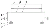
FIG. 1 is a schematic structural view of the present invention;
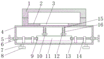
FIG. 2 is a schematic view of the inner cavity structure of the upper mold, the lower mold and the carrying case of the present invention;
fig. 3 is a schematic diagram of the structure on the right side of the guide plate of the present invention.
In the figure: 1. an upper die; 2. a lower die; 3. pushing the plate; 4. a carrying case; 5. a handle; 6. a threaded sleeve; 7. a support pillar; 8. a non-slip mat; 9. a card slot; 10. connecting blocks; 11. clamping a plate; 12. a limiting plate; 13. a screw; 14. a guide plate; 15. a push rod; 16. a tension spring.
Detailed Description
The technical solutions in the embodiments of the present invention will be described clearly and completely with reference to the accompanying drawings in the embodiments of the present invention, and it is obvious that the described embodiments are only some embodiments of the present invention, not all embodiments. Based on the embodiments in the present invention, all other embodiments obtained by a person skilled in the art without creative work belong to the protection scope of the present invention.
In the description of the present invention, it should be noted that the terms "upper", "lower", "inner", "outer", "front end", "rear end", "both ends", "one end", "the other end", and the like indicate orientations or positional relationships based on the orientations or positional relationships shown in the drawings, and are only for convenience of description and simplification of description, but do not indicate or imply that the device or element to be referred must have a specific orientation, be constructed in a specific orientation, and be operated, and thus, should not be construed as limiting the present invention. Furthermore, the terms "first" and "second" are used for descriptive purposes only and are not to be construed as indicating or implying relative importance.
In the description of the present invention, it is to be noted that, unless otherwise explicitly specified or limited, the terms "mounted", "provided", "connected", and the like are to be construed broadly, such as "connected", which may be fixedly connected, detachably connected, or integrally connected; can be mechanically or electrically connected; they may be connected directly or indirectly through intervening media, or they may be interconnected between two elements. The specific meaning of the above terms in the present invention can be understood in specific cases to those skilled in the art.
The standard parts used in the application document can be purchased from the market, and can be customized according to the description of the specification and the description of the attached drawings, the specific connection mode of each part adopts conventional means such as mature bolts, rivets, welding and the like in the prior art, and machines, parts and equipment adopt conventional models in the prior art.
The utility model discloses an go up mould 1, bed die 2, push pedal 3, bearing box 4, handle 5, swivel nut 6, support column 7, slipmat 8, draw-in groove 9, connecting block 10, cardboard 11, limiting plate 12, screw rod 13, deflector 14, push rod 15 and extension spring 16 part are the general standard or the part that technical staff in the field knows, and its structure and principle all are that this technical staff all can learn through the technical manual or learn through conventional test method.
Referring to fig. 1-3, an automatic elastic material accessory for an injection mold comprises an upper mold 1 and a lower mold 2, wherein the upper mold 1 is positioned at the top of the lower mold 2, a carrying box 4 is arranged at the bottom of the lower mold 2, supporting columns 7 are fixedly connected to both sides of the bottom of the carrying box 4, and anti-slip pads 8 are fixedly connected to the bottoms of the two supporting columns 7, the utility model can fix the carrying box 4 through the supporting columns 7 and the anti-slip pads 8, so that the carrying box 4 has better effect when in use, and the situation that the carrying box 4 has poor use effect due to movement of the carrying box 4 when in use is avoided, a push plate 3 is arranged at the bottom of an inner cavity of the lower mold 2, the outer surface of the push plate 3 is in seamless connection with the lower mold 2, push rods 15 are arranged at both sides of the bottom of the push plate 3, the bottom of the push rods 15 penetrates through and extends to the inner cavity of the carrying, the connecting part of the top of the limiting plate 12 and the bearing box 4 is sleeved with a tension spring 16, the bottom of the push rod 15 is provided with a clamping plate 11, the two sides of the top of the clamping plate 11 are fixedly connected with the connecting part of the push rod 15 through the connecting block 10, the push rod 15 can be fixed through the connecting block 10, the situation that the push rod 15 falls down due to looseness of the push rod 15 when the push rod 15 is used for a long time is avoided, the two push rods 15 are centrosymmetric about the clamping plate 11, the two sides of the clamping plate 11 are both provided with clamping grooves 9, the bottoms of the two sides of the bearing box 4 are both sleeved with screw sleeves 6, the inner cavities of the screw sleeves 6 are in threaded connection with screw rods 13, the two sides of the surfaces of the screw rods 13 are both sleeved with guide plates 14, the bottoms of the guide plates 14 are fixedly connected with the bearing box 4 through fixing parts, the outer sides of the screw rods 13, the inboard of screw rod 13 and the draw-in groove 9 joint on the cardboard 11, the utility model discloses an upper die 1, bed die 2, the push pedal 3, the bearing box 4, handle 5, swivel nut 6, draw-in groove 9, cardboard 11, limiting plate 12, screw rod 13, deflector 14, push rod 15 and extension spring 16 mutually support, can be when injection mold is using, can play the effect of automatic bullet material to injection mold, avoided current injection mold when using, injection mold does not possess the effect of automatic bullet material, thereby lead to the loaded down with trivial details situation of flow when manual material of getting, be fit for using widely.
When the clamping plate is used, the push plate 3 is pressed downwards, the push rod 15 is driven to move downwards through the push plate 3, the tension spring 16 is driven to move downwards through the limiting plate 12 on the push rod 15, the handle 5 is rotated, the screw rod 13 is driven to rotate through the handle 5, the screw rod 13 is driven to move inwards through the threaded sleeve 6, and the clamping plate can be fixedly used when the screw rod 13 moves to the clamping groove 9 on the clamping plate 11;
when needing the ejection of compact, rotate handle 5, drive screw rod 13 through handle 5 and rotate, through the outside removal of 6 cooperation screw rods 13 of swivel nut, when shifting out draw-in groove 9 on the cardboard 11 through screw rod 13, drive limiting plate 12 through the inertia of extension spring 16 and upwards remove, drive push rod 15 rebound through limiting plate 12, drive push pedal 3 rebound through push rod 15, through the push pedal 3 release the shaping material can.
Although embodiments of the present invention have been shown and described, it will be appreciated by those skilled in the art that changes, modifications, substitutions and alterations can be made in these embodiments without departing from the principles and spirit of the invention, the scope of which is defined in the appended claims and their equivalents.
Claims (5)
1. The utility model provides an injection mold is with automatic bullet material accessory, includes mould (1) and bed die (2), its characterized in that: the upper die (1) is located at the top of the lower die (2), the bottom of the lower die (2) is provided with a bearing box (4), the bottom of the inner cavity of the lower die (2) is provided with a push plate (3), the outer surface of the push plate (3) is in seamless connection with the lower die (2), push rods (15) are arranged on two sides of the bottom of the push plate (3), the bottom of each push rod (15) penetrates through and extends to the inner cavity of the bearing box (4), a limiting plate (12) is sleeved on the surface of each push rod (15), a tension spring (16) is sleeved at the joint of the top of each limiting plate (12) and the bearing box (4), a clamping plate (11) is arranged at the bottom of each push rod (15), clamping grooves (9) are formed in two sides of each clamping plate (11), threaded sleeves (6) are arranged at the bottoms of two sides of each bearing box (4), a screw rod (13) is, the outer side of the screw rod (13) is provided with a handle (5), and the inner side of the screw rod (13) is clamped with a clamping groove (9) on the clamping plate (11).
2. The automatic spring part for injection mold according to claim 1, characterized in that: the supporting box is characterized in that supporting columns (7) are fixedly connected to two sides of the bottom of the bearing box (4), and anti-slip pads (8) are fixedly connected to the bottoms of the two supporting columns (7).
3. The automatic spring part for injection mold according to claim 1, characterized in that: the connection parts of the two sides of the top of the clamping plate (11) and the push rods (15) are fixedly connected through a connecting block (10), and the two push rods (15) are centrosymmetric relative to the clamping plate (11).
4. The automatic spring part for injection mold according to claim 1, characterized in that: the surface of the handle (5) is sleeved with an anti-slip sleeve, and the inner cavity of the anti-slip sleeve is fixedly connected with the handle (5) through an adhesive.
5. The automatic spring part for injection mold according to claim 1, characterized in that: both sides on screw rod (13) surface all overlap and are equipped with deflector (14), and the bottom and the bearing box (4) of deflector (14) pass through mounting fixed connection.
Priority Applications (1)
| Application Number | Priority Date | Filing Date | Title |
|---|---|---|---|
| CN202021551686.0U CN213412796U (en) | 2020-07-31 | 2020-07-31 | Automatic elastic part for injection mold |
Applications Claiming Priority (1)
| Application Number | Priority Date | Filing Date | Title |
|---|---|---|---|
| CN202021551686.0U CN213412796U (en) | 2020-07-31 | 2020-07-31 | Automatic elastic part for injection mold |
Publications (1)
| Publication Number | Publication Date |
|---|---|
| CN213412796U true CN213412796U (en) | 2021-06-11 |
Family
ID=76255471
Family Applications (1)
| Application Number | Title | Priority Date | Filing Date |
|---|---|---|---|
| CN202021551686.0U Active CN213412796U (en) | 2020-07-31 | 2020-07-31 | Automatic elastic part for injection mold |
Country Status (1)
| Country | Link |
|---|---|
| CN (1) | CN213412796U (en) |
-
2020
- 2020-07-31 CN CN202021551686.0U patent/CN213412796U/en active Active
Similar Documents
| Publication | Publication Date | Title |
|---|---|---|
| CN211363270U (en) | Injection mold convenient to drawing of patterns | |
| CN210257137U (en) | Injection mold convenient to take off material | |
| CN112297360A (en) | Injection mold that breaks away from fast | |
| CN213412796U (en) | Automatic elastic part for injection mold | |
| CN209999620U (en) | type automobile injection mold's slider thimble ejection mechanism | |
| CN211640845U (en) | Injection molding machine demoulding structure with uniform stress | |
| CN211390006U (en) | Demoulding mechanism for injection mould of storage box of automobile door | |
| CN212021557U (en) | Universal plastic package mold frame for semiconductor | |
| CN212045709U (en) | Injection mold for sleeve | |
| CN218083867U (en) | Automatic rubber wheel demolding jig | |
| CN215320216U (en) | High-precision radiating fin processing die | |
| CN212554641U (en) | Die convenient to install | |
| CN220075363U (en) | Injection molding machine | |
| CN216708200U (en) | Single-cavity plastic injection mold | |
| CN215359702U (en) | Ejecting device for injection mold | |
| CN220008596U (en) | Automatic demolding injection molding device | |
| CN114161628B (en) | Anti-slip glasses support film pressing device for glasses production | |
| CN212733602U (en) | Industry aluminum product extrusion die convenient to fixed mounting | |
| CN216578950U (en) | Injection molding mould for plastic product | |
| CN211917565U (en) | Efficient injection mold and ejection mechanism | |
| CN214395139U (en) | High-efficiency energy-saving pressure maintaining device of building block piece injection molding equipment | |
| CN212097325U (en) | Socket splashproof box mold processing | |
| CN219381345U (en) | Foaming mould capable of being positioned rapidly | |
| CN218948292U (en) | Injection mold convenient to drawing of patterns | |
| CN209224418U (en) | Mold is used in a kind of injection molding of plasthetics |
Legal Events
| Date | Code | Title | Description |
|---|---|---|---|
| GR01 | Patent grant | ||
| GR01 | Patent grant |