CN213391096U - Distribution network overhauls uses lift platform box - Google Patents
Distribution network overhauls uses lift platform box Download PDFInfo
- Publication number
- CN213391096U CN213391096U CN202020826104.9U CN202020826104U CN213391096U CN 213391096 U CN213391096 U CN 213391096U CN 202020826104 U CN202020826104 U CN 202020826104U CN 213391096 U CN213391096 U CN 213391096U
- Authority
- CN
- China
- Prior art keywords
- fixedly connected
- support frame
- distribution network
- box
- power distribution
- Prior art date
- Legal status (The legal status is an assumption and is not a legal conclusion. Google has not performed a legal analysis and makes no representation as to the accuracy of the status listed.)
- Active
Links
- 238000005096 rolling process Methods 0.000 claims description 4
- 238000012423 maintenance Methods 0.000 abstract description 5
- 230000006872 improvement Effects 0.000 description 9
- 230000015556 catabolic process Effects 0.000 description 6
- 235000017166 Bambusa arundinacea Nutrition 0.000 description 4
- 235000017491 Bambusa tulda Nutrition 0.000 description 4
- 241001330002 Bambuseae Species 0.000 description 4
- 235000015334 Phyllostachys viridis Nutrition 0.000 description 4
- 239000011425 bamboo Substances 0.000 description 4
- 238000004891 communication Methods 0.000 description 3
- 230000003028 elevating effect Effects 0.000 description 3
- 230000005484 gravity Effects 0.000 description 3
- 230000000694 effects Effects 0.000 description 2
- 238000000034 method Methods 0.000 description 2
- 230000008439 repair process Effects 0.000 description 2
- 238000000926 separation method Methods 0.000 description 2
- 230000009471 action Effects 0.000 description 1
- 230000009286 beneficial effect Effects 0.000 description 1
- 230000003139 buffering effect Effects 0.000 description 1
- 230000008859 change Effects 0.000 description 1
- 238000011161 development Methods 0.000 description 1
- 230000014509 gene expression Effects 0.000 description 1
- 239000000463 material Substances 0.000 description 1
- 238000012856 packing Methods 0.000 description 1
- 230000004044 response Effects 0.000 description 1
Images


Landscapes
- Handcart (AREA)
Abstract
The utility model discloses a distribution network overhauls uses lift platform box relates to distribution network maintenance platform field, has overhauld the switching with inconvenient removal of lift platform and location to current distribution network, and the limited problem in space, now proposes following scheme, and it includes the bottom plate, the spacing box of up end fixedly connected with of bottom plate, the lower inner wall of spacing box is provided with scissors type support frame, the upper end fixedly connected with layer board of scissors type support frame, the up end fixedly connected with support frame of layer board, the equal fixedly connected with brace table in left and right both sides of layer board upper surface, the support frame internal rotation is connected with the work platform frame, the up end of the left and right both sides of spacing box is provided with the cylinder, the lower inner wall of spacing box is provided with the carriage, the upper inner wall of carriage is provided with first hydraulic stem. The device has the characteristics of convenient parking or movement, great increase of working space and convenient folding and transferring.
Description
Technical Field
The utility model relates to a distribution network overhauls the platform field, especially relates to a distribution network overhauls uses lift platform box.
Background
With the development of society, the power and communication industries are more and more important to the lives of people and cannot be separated from the power and communication industries at all times, so that once a line fails, the life of people is seriously influenced. In order to ensure the breakdown rush repair work, each basic unit is equipped with the breakdown van, but the current breakdown van has the sign in addition to outward appearance, and inner structure and ordinary passenger-cargo convertible car do not have the difference, can't satisfy the quick, safe convenient basic demand of breakdown work reaction.
The distribution network of the power system needs to be loaded with tools, materials and the like. At present, the most common electric power system distribution network breakdown van is a special electric power maintenance van and a pick-up truck.
Most of all power supply stations use pick-up trucks as breakdown van, the front row is double-row seats, 5 people can take, the back is open packing box, although this pick-up truck is with low costs, can accomplish that each overhaul team and power supply station are equipped with, but it is inconvenient to use, work efficiency is low.
Electric power tool car is the engineering car that the electric wire netting staff used in patrolling and examining or handling the electric power accident, current electric power tool car mostly has the elevating platform, be convenient for overhaul the power equipment of eminence, but power equipment mostly all sets up in more remote position, for example install the wire pole in farmland, and the elevating platform on the electric power tool car all is fixed on the car hopper, when overhauling on the wire pole in farmland or the power equipment of the unable position that is close to of other vehicles, the elevating platform can not be close to power equipment, can only assist through carrying the ladder, lead to maintenance inefficiency, and the ladder erects on the ground of unevenness unstable, bring the hidden danger for maintainer's personal safety.
The price increasing device of the existing electric power maintenance vehicle cannot meet the basic requirements of quick response, safety and convenience of emergency repair work. And the space is limited, and the switching of moving and positioning can not be conveniently carried out in the operation. Therefore, a lifting platform for power distribution network maintenance is provided.
SUMMERY OF THE UTILITY MODEL
The utility model provides a pair of distribution network overhauls uses lift platform box has solved the switching of the inconvenient removal of current distribution network overhauls with lift platform and location, and the limited problem in space.
In order to achieve the above purpose, the utility model adopts the following technical scheme:
the utility model provides a distribution network overhauls uses lift platform box, includes the bottom plate, the spacing box of up end fixedly connected with of bottom plate, the lower inner wall of spacing box is provided with scissors type support frame, the upper end fixedly connected with layer board of scissors type support frame, the up end fixedly connected with support frame of layer board, the equal fixedly connected with brace table in left and right both sides of layer board upper surface, the support frame internal rotation is connected with the work platform frame.
As a further improvement of the utility model,
the upper end surfaces of the left side and the right side of the limiting box are provided with rollers, and the lower inner wall of the limiting box is provided with a supporting frame; the upper inner wall of the supporting frame is provided with a first hydraulic rod, and the lower end of the first hydraulic rod is fixedly connected with a push block.
As a further improvement of the utility model,
the equal fixedly connected with of left and right both sides of terminal surface under the bottom plate is spacing section of thick bamboo, sliding sleeve is equipped with the slide bar in the spacing section of thick bamboo, the both ends of slide bar fixedly connected with voussoir and stationary blade respectively.
As a further improvement of the utility model,
and a spring is connected between the limiting cylinder and the wedge block and sleeved on the surface of the sliding rod.
As a further improvement of the utility model,
the front end and the rear end of the support frame are rotatably connected to the inner walls of the front side and the rear side of the support frame through rotating shafts.
As a further improvement of the utility model,
the support frame is characterized in that the front end face and the rear end face of the support frame are fixedly connected with limiting blocks, and the lower end faces of the limiting blocks are mutually limited with the upper end faces of the front side and the rear side of the support frame.
As a further improvement of the utility model,
each roller is connected with the ground of the support frame on one side of the roller in a rolling manner.
As a further improvement of the utility model,
the end of the two sides, close to each other, of the sliding rod is fixedly connected with a wedge block, and the end of the two sides, far away from each other, of the sliding rod is fixedly connected with a fixing piece.
As a further improvement of the utility model,
the sliding rods on the left side and the right side are sleeved in the limiting cylinder in a sliding manner.
As a further improvement of the utility model,
the lower end of the push block is connected with the wedge blocks on the left side and the right side in a matching mode.
Compared with the prior art, the beneficial effects of the utility model are that:
through bottom plate, spacing box, scissors type support frame, layer board, support frame, a supporting bench, work platform frame, cylinder, ejector pad, spacing section of thick bamboo, slide bar, voussoir, stationary blade for this device can release spacing box with layer board and support frame through scissors type support frame, and then drives the work platform frame and shifts up, and under the pivoted is connected, the work platform frame will rotate under the effect of gravity, and then rotation to the horizontality that can be convenient.
And the limiting block and the supporting table are stably limited, and meanwhile, the pushing block can be pushed by the hydraulic rod to move downwards, the sliding rods are driven to be away from each other through the matched connection with the wedge blocks on the two sides, and then the fixing pieces which are away from one end of each other are pushed to be positioned with the pulleys on the bottom plates on one sides of the fixing pieces.
Meanwhile, the separation can be conveniently carried out, so that the bottom plate can be conveniently parked or pushed.
The device has the characteristics of convenient parking or movement, great increase of working space and convenient folding and transferring.
Drawings
In order to more clearly illustrate the technical solutions in the embodiments of the present invention, the drawings needed for the embodiments or the prior art descriptions will be briefly described below, and it is obvious that the drawings in the following description are only some embodiments of the present invention, and it is obvious for those skilled in the art to obtain other drawings without creative efforts.
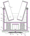
Fig. 1 is the utility model discloses a distribution network overhauls with lift platform's cross-sectional view of structure.
Fig. 2 is the utility model discloses a distribution network overhauls with lift platform's a section view of looking sideways at structure.
Fig. 3 is a schematic view of the connection position of the limiting cylinder and the sliding rod of the present invention.
Reference numbers in the figures: the device comprises a base plate 1, a limiting box 2, a scissor-type supporting frame 3, a supporting plate 4, a supporting frame 5, a supporting table 6, a working platform frame 7, a roller 8, a pushing block 9, a limiting barrel 10, a sliding rod 11, a wedge block 12 and a fixing plate 13.
Detailed Description
The technical solutions in the embodiments of the present application will be clearly and completely described below with reference to the drawings in the embodiments of the present application, and it is obvious that the described embodiments are only a part of the embodiments of the present application, and not all of the embodiments. The following description of at least one exemplary embodiment is merely illustrative in nature and is in no way intended to limit the application, its application, or uses. All other embodiments, which can be derived by a person skilled in the art from the embodiments given herein without making any creative effort, shall fall within the protection scope of the present application.
It is noted that the terminology used herein is for the purpose of describing particular embodiments only and is not intended to be limiting of example embodiments according to the present application. As used herein, the singular forms "a", "an" and "the" are intended to include the plural forms as well, and it should be understood that when the terms "comprises" and/or "comprising" are used in this specification, they specify the presence of stated features, steps, operations, devices, components, and/or combinations thereof, unless the context clearly indicates otherwise.
The relative arrangement of the components and steps, the numerical expressions, and numerical values set forth in these embodiments do not limit the scope of the present application unless specifically stated otherwise. Meanwhile, it should be understood that the sizes of the respective portions shown in the drawings are not drawn in an actual proportional relationship for the convenience of description. Techniques, methods, and apparatus known to those of ordinary skill in the relevant art may not be discussed in detail but are intended to be part of the specification where appropriate. In all examples shown and discussed herein, any particular value should be construed as merely illustrative, and not limiting.
Thus, other examples of the exemplary embodiments may have different values. It should be noted that: like reference numbers and letters refer to like items in the following figures, and thus, once an item is defined in one figure, further discussion thereof is not required in subsequent figures.
In the description of the present application, it is to be understood that the orientation or positional relationship indicated by the directional terms such as "front, rear, upper, lower, left, right", "lateral, vertical, horizontal" and "top, bottom", etc., are generally based on the orientation or positional relationship shown in the drawings, and are used for convenience of description and simplicity of description only, and in the case of not making a reverse description, these directional terms do not indicate and imply that the device or element being referred to must have a particular orientation or be constructed and operated in a particular orientation, and therefore, should not be considered as limiting the scope of the present application; the terms "inner and outer" refer to the inner and outer relative to the profile of the respective component itself.
Example one
As shown in the attached figures 1-3,
the utility model provides a distribution network overhauls uses lift platform box, includes bottom plate 1, the spacing box 2 of up end fixedly connected with of bottom plate 1, the lower inner wall of spacing box 2 is provided with scissors type support frame 3, a serial communication port, scissors type support frame 3's upper end fixedly connected with layer board 4, the up end fixedly connected with support frame 5 of layer board 6, the equal fixedly connected with brace table 6 in the left and right both sides of layer board 6 upper surface, 5 internal rotations of support frame are connected with work platform frame 7.
In this embodiment, the up end of the left and right both sides of spacing box 2 is provided with cylinder 8, the lower inner wall of spacing box 2 is provided with the carriage, the last inner wall of carriage is provided with first hydraulic stem, the lower extreme fixedly connected with ejector pad 9 of first hydraulic stem.
In this embodiment, the left and right sides of the lower end surface of the bottom plate 1 are both fixedly connected with a limiting cylinder 10, a sliding sleeve is arranged in the limiting cylinder 10 and is provided with a sliding rod 11, and two ends of the sliding rod 11 are respectively and fixedly connected with a wedge block 12 and a fixing piece 13.
In this embodiment, the front and rear ends of the support frame 5 are rotatably connected to the inner walls of the front and rear sides of the support frame 3 through the rotating shaft.
In this embodiment, the equal fixedly connected with stopper in preceding, the back both ends face of support frame 5, the lower terminal surface of stopper and the up end of support frame 3 preceding, back both sides are spacing mutually.
In this embodiment, each roller 8 is in rolling connection with the ground of the support frame 5 on one side.
In this embodiment, a wedge 12 is fixedly connected to a close end of the sliding rod 11 at both sides, and a fixing plate 13 is fixedly connected to a far end.
In this embodiment, the slide bars 11 on the left and right sides are slidably sleeved in the limiting cylinder 10.
In this embodiment, the lower end of the push block 9 is connected with the wedge blocks 12 on the left and right sides in a matching manner.
This embodiment is through bottom plate, spacing box, scissors type support frame, layer board, support frame, brace table, work platform frame, cylinder, ejector pad, spacing section of thick bamboo, slide bar, voussoir, stationary blade for this device can release spacing box with layer board and support frame through scissors type support frame, and then drives the work platform frame and shifts up, and under the pivoted is connected, the work platform frame will rotate under the effect of gravity, and then rotation to the horizontality that can be convenient.
And the limiting block and the supporting table are stably limited, and meanwhile, the pushing block can be pushed by the hydraulic rod to move downwards, the sliding rods are driven to be away from each other through the matched connection with the wedge blocks on the two sides, and then the fixing pieces which are away from one end of each other are pushed to be positioned with the pulleys on the bottom plates on one sides of the fixing pieces.
Meanwhile, the separation can be conveniently carried out, so that the bottom plate can be conveniently parked or pushed.
The device has the characteristics of convenient parking or movement, great increase of working space and convenient folding and transferring.
Example two
Referring to fig. 1-3, in the present embodiment, based on the first embodiment, a spring is connected between the limiting cylinder 10 and the wedge 12, and the spring is sleeved on the surface of the sliding rod 11; the spring has a buffering function and provides elastic force, so that the matching between the wedge block 12 and the limiting cylinder 10 is convenient for reaching a balance position, and the adjustment between the wedge block and the limiting cylinder is easier.
The utility model provides a distribution network overhauls uses lift platform, includes bottom plate 1, the spacing box 2 of up end fixedly connected with of bottom plate 1, the lower inner wall of spacing box 2 is provided with scissors type support frame 3, scissors type support frame 3's upper end fixedly connected with layer board 4, the up end fixedly connected with support frame 5 of layer board 6, the equal fixedly connected with brace table 6 in the left and right both sides of layer board 6 upper surface, 5 internal rotations of support frame are connected with work platform frame 7.
In this embodiment, the up end of the left and right both sides of spacing box 2 is provided with cylinder 8, and the lower inner wall of spacing box 2 is provided with the carriage, and the last inner wall of carriage is provided with first hydraulic stem, the lower extreme fixedly connected with ejector pad 9 of first hydraulic stem.
In this embodiment, the left and right sides of the lower end surface of the bottom plate 1 are both fixedly connected with a limiting cylinder 10, a sliding sleeve is arranged in the limiting cylinder 10 and is provided with a sliding rod 11, and two ends of the sliding rod 11 are respectively and fixedly connected with a wedge 12 and a fixing piece 13.
In this embodiment, a spring is connected between the limiting cylinder 10 and the wedge 12, and the spring is sleeved on the surface of the sliding rod 11.
In this embodiment, the front and rear ends of the supporting frame 5 are rotatably connected to the inner walls of the front and rear sides of the supporting frame 3 through the rotating shaft.
In this embodiment, the equal fixedly connected with stopper of preceding, the back both ends face of support frame 5, the lower terminal surface of stopper and the up end of support frame 3 preceding, back both sides are spacing mutually.
In this embodiment, each roller 8 is in rolling connection with the ground of the support frame 5 on one side.
In this embodiment, the end of the sliding rod 11 on both sides close to each other is fixedly connected with a wedge 12, and the end far away from each other is fixedly connected with a fixing plate 13.
In this embodiment, the sliding rods 11 on the left and right sides are slidably sleeved in the limiting cylinder 10, and the lower end of the pushing block 9 is connected with the wedges 12 on the left and right sides in a matching manner.
The working principle is as follows: when the device is used, the supporting plate and the supporting frame 5 can be pushed out of the limiting box 2 through the scissor-type supporting frame 3, and then the working platform frame 7 is driven to move upwards;
under the rotary connection, the working platform frame 7 rotates under the action of gravity, and further can conveniently rotate to a horizontal state;
the limit block and the support table 6 are stably limited, and meanwhile, the push block 9 can be pushed to move downwards through a hydraulic rod and is in matched connection with wedge blocks 12 on two sides to drive the slide rods 11 to move away from each other;
and then promote the stationary blade 13 of keeping away from one end each other and fix a position with the pulley on the bottom plate 1 of respective one side, simultaneously can be convenient separate for can be convenient stop or promote bottom plate 1.
The above, only be the concrete implementation of the preferred embodiment of the present invention, but the protection scope of the present invention is not limited thereto, and any person skilled in the art is in the technical scope of the present invention, according to the technical solution of the present invention and the utility model, the concept of which is equivalent to replace or change, should be covered within the protection scope of the present invention.
Claims (10)
1. The utility model provides a distribution network overhauls uses lift platform box, includes bottom plate (1), the spacing box of up end fixedly connected with (2) of bottom plate (1), the lower inner wall of spacing box (2) is provided with scissors type support frame (3), its characterized in that, the upper end fixedly connected with layer board (4) of scissors type support frame (3), up end fixedly connected with support frame (5) of layer board (4), the equal fixedly connected with brace table (6) in left and right both sides of layer board (4) upper surface, support frame (5) internal rotation is connected with work platform frame (7).
2. The lifting platform box for overhauling the power distribution network according to claim 1, wherein rollers (8) are arranged on the upper end faces of the left side and the right side of the limiting box (2), a supporting frame is arranged on the lower inner wall of the limiting box (2), a first hydraulic rod is arranged on the upper inner wall of the supporting frame, and a pushing block (9) is fixedly connected to the lower end of the first hydraulic rod.
3. The lifting platform box for overhauling the power distribution network according to claim 2, wherein the left side and the right side of the lower end surface of the bottom plate (1) are both fixedly connected with a limiting cylinder (10), a sliding rod (11) is sleeved in the limiting cylinder (10) in a sliding manner, and two ends of the sliding rod (11) are respectively and fixedly connected with a wedge block (12) and a fixing plate (13).
4. The lifting platform box for overhauling the power distribution network as recited in claim 3, wherein a spring is connected between the limiting cylinder (10) and the wedge block (12), and the spring is sleeved on the surface of the sliding rod (11).
5. The lifting platform box for overhauling the power distribution network according to claim 1, wherein the front end and the rear end of the support frame (5) are rotatably connected to the inner walls of the front side and the rear side of the support frame (5) through rotating shafts.
6. The lifting platform box for overhauling the power distribution network according to claim 5, wherein the front end face and the rear end face of the support frame (5) are fixedly connected with limit blocks, and the lower end faces of the limit blocks are mutually limited with the upper end faces of the front side and the rear side of the support frame (5).
7. Lifting platform box for overhaul of power distribution networks according to claim 2, characterized in that each roller (8) is in rolling connection with the ground of the support frame (5) on its respective side.
8. The lifting platform box for overhauling the power distribution network according to claim 4, wherein a wedge (12) is fixedly connected to one end of the sliding rod (11) at two sides close to each other, and a fixing plate (13) is fixedly connected to one end of the sliding rod away from each other.
9. The lifting platform box for overhauling the power distribution network according to claim 4, wherein the sliding rods (11) on the left side and the right side are slidably sleeved in the limiting cylinder (10).
10. The lifting platform box for overhauling the power distribution network according to claim 4, wherein the lower end of the push block (9) is connected with the wedge blocks (12) on the left side and the right side in a matching manner.
Priority Applications (1)
| Application Number | Priority Date | Filing Date | Title |
|---|---|---|---|
| CN202020826104.9U CN213391096U (en) | 2020-05-18 | 2020-05-18 | Distribution network overhauls uses lift platform box |
Applications Claiming Priority (1)
| Application Number | Priority Date | Filing Date | Title |
|---|---|---|---|
| CN202020826104.9U CN213391096U (en) | 2020-05-18 | 2020-05-18 | Distribution network overhauls uses lift platform box |
Publications (1)
| Publication Number | Publication Date |
|---|---|
| CN213391096U true CN213391096U (en) | 2021-06-08 |
Family
ID=76178003
Family Applications (1)
| Application Number | Title | Priority Date | Filing Date |
|---|---|---|---|
| CN202020826104.9U Active CN213391096U (en) | 2020-05-18 | 2020-05-18 | Distribution network overhauls uses lift platform box |
Country Status (1)
| Country | Link |
|---|---|
| CN (1) | CN213391096U (en) |
-
2020
- 2020-05-18 CN CN202020826104.9U patent/CN213391096U/en active Active
Similar Documents
| Publication | Publication Date | Title |
|---|---|---|
| CN202245820U (en) | Small-sized electric sling cart | |
| CN103193179A (en) | Scissor-type airbag lifting machine | |
| CN205773089U (en) | A kind of single or double fork hydraulic lifting platform | |
| CN213391096U (en) | Distribution network overhauls uses lift platform box | |
| CN213679707U (en) | Lift for construction | |
| CN210794873U (en) | Transfer auxiliary device of inspection robot of transformer substation | |
| CN107324241B (en) | Yardage roll lifting carrying trolley | |
| CN210176373U (en) | Lifting machine | |
| CN111711329B (en) | Maintenance trolley suitable for high-power motor | |
| CN110203847B (en) | Lifting machine | |
| CN211946176U (en) | Side electric lifting platform for railway vehicle | |
| CN212050426U (en) | Municipal works are with elevating gear that speedily carries out rescue work | |
| CN211664634U (en) | Oil top handling tool | |
| CN211998680U (en) | Movable hydraulic lifting platform | |
| CN212825176U (en) | Elevating platform for overhauling magnetic resonance scanner | |
| CN210438108U (en) | Limiting and fixing structure for mobile dock leveler | |
| CN112723234A (en) | Utilize intelligent storage workshop in high-rise space | |
| CN212292718U (en) | Novel heavy object rises to rise and moves fortune ware | |
| CN204714479U (en) | A kind of shearing mobile lift | |
| CN213011870U (en) | Elevator for electric power installation engineering | |
| CN215048451U (en) | Fork frame for scissor lift | |
| CN210710628U (en) | Civil engineering elevating gear | |
| CN216038429U (en) | Movable hydraulic lifting platform | |
| CN215558676U (en) | Double-layer jacking lifting platform | |
| CN203922607U (en) | Information machine room telephone-moving platform truck device |
Legal Events
| Date | Code | Title | Description |
|---|---|---|---|
| GR01 | Patent grant | ||
| GR01 | Patent grant |