CN213381840U - Quick slicer of cake - Google Patents
Quick slicer of cake Download PDFInfo
- Publication number
- CN213381840U CN213381840U CN202022173200.0U CN202022173200U CN213381840U CN 213381840 U CN213381840 U CN 213381840U CN 202022173200 U CN202022173200 U CN 202022173200U CN 213381840 U CN213381840 U CN 213381840U
- Authority
- CN
- China
- Prior art keywords
- bread
- cutter
- rotary drum
- rapid
- type transmission
- Prior art date
- Legal status (The legal status is an assumption and is not a legal conclusion. Google has not performed a legal analysis and makes no representation as to the accuracy of the status listed.)
- Active
Links
Images

Landscapes
- Manufacturing And Processing Devices For Dough (AREA)
Abstract
The application discloses a rapid cake slicing machine which comprises a base, wherein a wheel type transmission belt driven by a stepping motor is arranged on the base, and a transmission channel for transmitting bread is arranged on the wheel type transmission belt; the rotary drum is positioned above the wheel type transmission belt, and a cutter is arranged on the outer side surface of the rotary drum. The utility model relates to a carry out mechanism that bread was carried through wheeled conveyer belt for get into the cutter working range that is driven by the rotary drum after the bread got into transfer passage, under the transfer of wheeled conveyer belt and the edge of a knife cutting of cutter, the bread of big rapidity was cut by the cutter, and the shaping is directly transported away through the containing box behind the small bread, replaces artifically, and is laborsaving, raises the efficiency. Simple structure and low cost.
Description
Technical Field
The application relates to the technical field of food processing, in particular to a rapid cake slicing machine.
Background
After cakes such as bread are baked and molded, a bread knife is needed for cutting, and second-time explosion is cut into flaky bread slices, so that the bread slices are convenient to sell and eat.
And the bread knife is used for cutting, which is tired and low in cutting efficiency.
SUMMERY OF THE UTILITY MODEL
The main objective of this application is to provide a quick slicer of cake to solve present problem.
In order to achieve the above object, the present application provides the following techniques:
a fast cake slicing machine comprises a base, wherein a wheel type transmission belt driven by a stepping motor is arranged on the base, and a conveying channel for conveying bread is arranged on the wheel type transmission belt; the rotary drum is positioned above the wheel type transmission belt, and a cutter is arranged on the outer side surface of the rotary drum.
Furthermore, a throwing plate for throwing the bread is arranged at the left end of the wheel type transmission belt.
Furthermore, a limiting opening is formed in the inlet of the conveying channel on the right side of the feeding plate.
Furthermore, a control panel for controlling the stepping motor is also arranged on the machine base.
Further, the rotary drum type conveying device further comprises an arc-shaped machine shell, the rotary drum is located in the arc-shaped machine shell, and the left end of the arc-shaped machine shell is fixed on the outer side face of the conveying channel through a rib plate.
Furthermore, a bread section containing box driven by a sliding rail is arranged on the right side of the wheel type transmission belt.
Furthermore, an arc sheet seat is arranged on the outer side surface of the rotary drum, an angle steel clamping plate is arranged on the arc sheet seat, and the cutter is installed on the angle steel clamping plate.
Compared with the prior art, this application can bring following technological effect:
the utility model relates to a carry out mechanism that bread was carried through wheeled conveyer belt for get into the cutter working range that is driven by the rotary drum after the bread got into transfer passage, under the transfer of wheeled conveyer belt and the edge of a knife cutting of cutter, the bread of big rapidity was cut by the cutter, and the shaping is directly transported away through the containing box behind the small bread, replaces artifically, and is laborsaving, raises the efficiency. Simple structure and low cost.
Drawings
The accompanying drawings, which are incorporated in and constitute a part of this application, serve to provide a further understanding of the application and to enable other features, objects, and advantages of the application to be more apparent. The drawings and their description illustrate the embodiments of the invention and do not limit it. In the drawings:
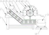
fig. 1 is a schematic diagram of a suitable structure of the present invention;
fig. 2 is an enlarged schematic view of a portion a of fig. 1 according to the present invention;
in the figure: 1. the bread dough slicing machine comprises a machine base, 2, a control panel, 3, a throwing plate, 4, a wheel type transmission belt, 5, a limiting opening, 6, a conveying channel, 7, a rib plate, 8, a rotary drum, 9, an arc-shaped machine shell, 10, a cutter, 11, a bread dough slicing storage box, 12, a sliding rail, 13, an arc sheet seat, 14 and an angle steel clamping plate.
Detailed Description
In order to make the technical solutions better understood by those skilled in the art, the technical solutions in the embodiments of the present application will be clearly and completely described below with reference to the drawings in the embodiments of the present application, and it is obvious that the described embodiments are only partial embodiments of the present application, but not all embodiments. All other embodiments, which can be derived by a person skilled in the art from the embodiments given herein without making any creative effort, shall fall within the protection scope of the present application.
It should be noted that the terms "first," "second," and the like in the description and claims of this application and in the drawings described above are used for distinguishing between similar elements and not necessarily for describing a particular sequential or chronological order. It should be understood that the data so used may be interchanged under appropriate circumstances such that embodiments of the application described herein may be used. Furthermore, the terms "comprises," "comprising," and "having," and any variations thereof, are intended to cover a non-exclusive inclusion, such that a process, method, system, article, or apparatus that comprises a list of steps or elements is not necessarily limited to those steps or elements expressly listed, but may include other steps or elements not expressly listed or inherent to such process, method, article, or apparatus.
In this application, the terms "upper", "lower", "left", "right", "front", "rear", "top", "bottom", "inner", "outer", "middle", "vertical", "horizontal", "lateral", "longitudinal", and the like indicate orientations or positional relationships based on the orientations or positional relationships shown in the drawings. These terms are used primarily to better describe the present application and its embodiments, and are not used to limit the indicated devices, elements or components to a particular orientation or to be constructed and operated in a particular orientation.
Moreover, some of the above terms may be used to indicate other meanings besides the orientation or positional relationship, for example, the term "on" may also be used to indicate some kind of attachment or connection relationship in some cases. The specific meaning of these terms in this application will be understood by those of ordinary skill in the art as appropriate.
In addition, the term "plurality" shall mean two as well as more than two.
It should be noted that the embodiments and features of the embodiments in the present application may be combined with each other without conflict. The present application will be described in detail below with reference to the embodiments with reference to the attached drawings.
Example 1
A fast cake slicing machine comprises a base 1, wherein a wheel type transmission belt 4 driven by a stepping motor is arranged on the base 1, and a transmission channel 6 for transmitting bread is arranged on the wheel type transmission belt 4; the cutting device is characterized by further comprising a rotary drum 8 driven by a stepping motor, wherein the rotary drum 8 is positioned above the wheel type transmission belt 4, and a cutter 10 is arranged on the outer side surface of the rotary drum 8.
The utility model relates to a carry out mechanism that bread was carried through wheeled conveyer belt 4 for get into the cutter 10 working range that is driven by rotary drum 8 after the bread got into transfer passage 6, under the transfer of wheeled conveyer belt 4 and the edge of a knife cutting of cutter 10, big fast bread was cut by cutter 10, and the shaping directly transports away through the containing box behind the small bread, replaces artifically, and is laborsaving, raises the efficiency. Simple structure and low cost.
As shown in attached drawings 1 and 2, a quick cake slicing machine comprises a base 1 with a slope structure, wherein a wheel type transmission belt 4 driven by a stepping motor is arranged on the base 1, the structure of the wheel type transmission belt 4 is as shown in attached drawing 1, the left part of the wheel type transmission belt is of the slope structure, the right part of the wheel type transmission belt is in a horizontal modeling shape, a cutting part such as a rotary drum 8 is arranged above the right part of the wheel type transmission belt, the corresponding wheel type transmission belt 4 is installed on the basis of the structure, the wheel type transmission belt 4 is driven by the stepping motor, the rotating speed of the stepping motor can be changed. In order to facilitate the bread conveying to the cutting working range, a conveying channel 6 for conveying the bread is arranged on the wheel type driving belt 4; the conveying channel 6 is a channel made of iron sheet or plastic skin, and bread can directly pass through the channel.
In order to set up cutting mechanism, still include through step motor driven rotary drum 8, rotary drum 8 direct mount on the assistant support of frame 1 can, rotary drum 8 is located wheeled drive belt 4 top, be equipped with cutter 10 on the rotary drum 8 lateral surface. The cutting knives 10 are uniformly arranged on the outer side surface of the rotary drum 8 in the circumference, rotate when the corresponding two stepping motors are started, the bread is conveyed to the conveying part of the horizontal part, enters the working range of the cutting knives 10 to be cut, and is cut into the bread when reaching the right side, and the bread is conveyed out from the wheel type transmission belt 4.
Further, a throwing plate 3 for throwing the bread is arranged at the left end of the wheel type transmission belt 4.
The throwing plate 3 is convenient for throwing blocky bread into the inlet of the conveying channel 6 and is a stainless steel plate which is welded on the upper surface of the shell of the wheel type transmission belt 4.
Furthermore, a limiting port 5 is arranged at the inlet of the conveying channel 6 at the right side of the feeding plate 3. Spacing mouth 5 is a tetrahedron structure of most open side, and left side and bottom surface opening, integrative welding are at 6 entrances of transfer passage, are convenient for restrict the bread of putting into, make it get into 6 entrances of transfer passage.
Furthermore, a control panel 2 for controlling the stepping motor is arranged on the machine base 1. The control panel 2 is provided with an adjusting knob which can respectively adjust the speed of the two stepping motors.
Further, the device also comprises an arc-shaped machine shell 9, the rotary drum 8 is positioned in the arc-shaped machine shell 9, and the left end of the arc-shaped machine shell 9 is fixed on the outer side surface of the conveying channel 6 through a rib plate 7.
In order to avoid the exposure of the drum 8 and the injury of the cutter 10, an arc-shaped housing 9 is arranged and can be welded on a secondary support of the machine base 1, and is fixed on the outer side surface of the conveying channel 6 through a rib plate 7 for improving the stability.
Furthermore, a bread section containing box 11 driven by a slide rail 12 is arranged on the right side of the wheel type transmission belt 4.
In order to directly store sliced bread, a bread slice storage box 11 driven by a slide rail 12 is arranged at the right side of the wheel type transmission belt 4. The storage and transportation are automatically realized.
Furthermore, an arc sheet seat 13 is arranged on the outer side surface of the rotary drum 8, an angle iron clamping plate 14 is arranged on the arc sheet seat, and the cutter 10 is installed on the angle iron clamping plate 14.
The above description is only a preferred embodiment of the present application and is not intended to limit the present application, and various modifications and changes may be made by those skilled in the art. Any modification, equivalent replacement, improvement and the like made within the spirit and principle of the present application shall be included in the protection scope of the present application.
Claims (7)
1. A rapid cake slicing machine is characterized by comprising a base (1), wherein a wheel type transmission belt (4) driven by a stepping motor is arranged on the base (1), and a conveying channel (6) for conveying bread is arranged on the wheel type transmission belt (4); still include through step motor driven rotary drum (8), rotary drum (8) are located wheeled drive belt (4) top, be equipped with cutter (10) on rotary drum (8) lateral surface.
2. A rapid pastry slicer as claimed in claim 1, wherein the left end of the wheel-type conveyor belt (4) is provided with a throwing plate (3) for throwing in bread.
3. A rapid pastry slicer as claimed in claim 2, characterized in that the inlet of the feed channel (6) on the right side of the drop plate (3) is provided with a limit opening (5).
4. A rapid pastry slicer as claimed in claim 3, wherein the base (1) is further provided with a control panel (2) for controlling the stepping motor.
5. A rapid pastry slicer as claimed in claim 1 or claim 4, further comprising an arcuate housing (9), wherein the drum (8) is located within the arcuate housing (9), and wherein the left end of the arcuate housing (9) is secured to the outside of the conveying path (6) by a rib (7).
6. A rapid pastry slicer as claimed in claim 5, characterized in that a bread-slice receiving box (11) is provided on the right side of the wheel-type conveyor belt (4) and is driven by a slide rail (12).
7. A rapid pastry slicer as claimed in claim 1 or 6, wherein the drum (8) is provided on its outer side with a cam seat (13) on which an angle iron clamp (14) is provided, and the cutter (10) is mounted on the angle iron clamp (14).
Priority Applications (1)
| Application Number | Priority Date | Filing Date | Title |
|---|---|---|---|
| CN202022173200.0U CN213381840U (en) | 2020-09-28 | 2020-09-28 | Quick slicer of cake |
Applications Claiming Priority (1)
| Application Number | Priority Date | Filing Date | Title |
|---|---|---|---|
| CN202022173200.0U CN213381840U (en) | 2020-09-28 | 2020-09-28 | Quick slicer of cake |
Publications (1)
| Publication Number | Publication Date |
|---|---|
| CN213381840U true CN213381840U (en) | 2021-06-08 |
Family
ID=76184331
Family Applications (1)
| Application Number | Title | Priority Date | Filing Date |
|---|---|---|---|
| CN202022173200.0U Active CN213381840U (en) | 2020-09-28 | 2020-09-28 | Quick slicer of cake |
Country Status (1)
| Country | Link |
|---|---|
| CN (1) | CN213381840U (en) |
-
2020
- 2020-09-28 CN CN202022173200.0U patent/CN213381840U/en active Active
Similar Documents
| Publication | Publication Date | Title |
|---|---|---|
| US3880069A (en) | Apparatus for forming dough shells | |
| JP2001514979A (en) | A slicing machine for slicing multiple food chunks simultaneously | |
| CN110574775A (en) | Raw beef cutting machine | |
| US4046920A (en) | Method for forming dough shells | |
| CN106808517B (en) | A kind of ultrasonic food cutting machine | |
| CN211322826U (en) | Raw beef cutting machine | |
| CN213381840U (en) | Quick slicer of cake | |
| CN111066865A (en) | Beef cutting device | |
| KR101394418B1 (en) | Horizontality cut working apparatus for chicken | |
| EP1487278B1 (en) | A method and device for cutting objects into fixed portions | |
| CN218428539U (en) | Cereal processing grinds potato machine | |
| JP5648228B2 (en) | Meat slicer and meat slice method | |
| CN112429344B (en) | Cubic bread cutting and packaging equipment | |
| CN210061269U (en) | Multi-blade bacon slicer | |
| CN212164741U (en) | Taro rounding machine | |
| CN213731979U (en) | Fresh meat slicer | |
| CN209812432U (en) | Dried meat slice slitting device | |
| CN211306421U (en) | Cutting and processing device for poria cocos rolling preparation | |
| CN204183611U (en) | Novel beef automatic clinical microtome | |
| CN112171770A (en) | Rice cake slitting device | |
| CN217123332U (en) | Chicken cutlet slicing device for processing food materials in catering | |
| CN219054460U (en) | Bread slicer | |
| CN211881967U (en) | Dough trimming device of ox horn bread trimmer | |
| CN215511310U (en) | Three-dimensional dicing machine of accurate cutting | |
| CN212464711U (en) | Recovery unit after cake leftover bits cutting |
Legal Events
| Date | Code | Title | Description |
|---|---|---|---|
| GR01 | Patent grant | ||
| GR01 | Patent grant |