CN213370602U - Office table convenient to install - Google Patents
Office table convenient to install Download PDFInfo
- Publication number
- CN213370602U CN213370602U CN202021528297.6U CN202021528297U CN213370602U CN 213370602 U CN213370602 U CN 213370602U CN 202021528297 U CN202021528297 U CN 202021528297U CN 213370602 U CN213370602 U CN 213370602U
- Authority
- CN
- China
- Prior art keywords
- fixedly connected
- cabinet
- storage cabinet
- working plate
- hinge
- Prior art date
- Legal status (The legal status is an assumption and is not a legal conclusion. Google has not performed a legal analysis and makes no representation as to the accuracy of the status listed.)
- Active
Links
Images

Abstract
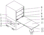
The utility model discloses a desk convenient to installation, including the locker, the inside both sides sliding connection of locker has puts the thing board, locker bottom fixedly connected with filing cabinet, filing cabinet bottom fixedly connected with universal wheel, the first hinge of the inside bottom fixedly connected with of locker, the first work board of one end fixedly connected with of locker is kept away from to first hinge, two second hinges of first work board bottom front side fixedly connected with, the one end fixedly connected with second work board of first work board is kept away from to the second hinge. The utility model discloses utilize the second hinge with first work board and second work board fifty percent discount, the bearing structure of first work board adopts easy dismouting structure, utilizes the coupling hook to support first work board, what the second workstation adopted is dismantled and assembled table leg, has set up the universal wheel here, makes things convenient for the transfer of table.
Description
Technical Field
The utility model mainly relates to an office table technical field, concretely relates to office table convenient to installation.
Background
The office table is a table which is convenient to work in daily life and social activities, and the work efficiency of the office table is greatly improved. The main consumer groups of the office table are divided into two categories, namely purchasing of enterprises and purchasing of governments, so that the work efficiency of the office table is greatly improved.
However, the existing office table is difficult to mount due to large volume, heavy weight and complex structure, and needs to be installed by professionals generally, and most of the office tables are directly contacted with the ground by plates after being mounted, so that the office table is troublesome to move and cannot be carried at will, and the requirement of work cannot be met sometimes.
SUMMERY OF THE UTILITY MODEL
The utility model mainly provides an office table convenient to install for solve the technical problem who proposes among the above-mentioned background art.
The utility model provides a technical scheme that above-mentioned technical problem adopted does:
an office table convenient to install comprises a storage cabinet, wherein a first object placing plate is connected to the upper portion of the inner wall of the storage cabinet in a sliding mode, a second object placing plate is connected to the lower portion of the inner wall of the storage cabinet in a sliding mode, a file cabinet is fixedly connected to the bottom of the storage cabinet, two drawers are arranged at the front end of the file cabinet, universal wheels are fixedly connected to the bottom of the file cabinet, a first hinge is fixedly connected to two ends of the front side of the inner bottom wall of the storage cabinet, a first rotary column is rotatably connected to the middle of the bottom of the first hinge, a first working plate is fixedly connected to one end, away from the storage cabinet, of the first hinge, a second round table is fixedly connected to two ends of the middle of the bottom of the first working plate, a first clamping ring is fixedly connected to the middle of the bottom of the second round table, a connecting hook is, the utility model discloses a file cabinet, including go-between, first hinge, first working plate, second hinge, connecting post, connecting table bottom four table legs, the connecting ring joint has the second snap ring, the first round platform of second snap ring rear side fixedly connected with, first round platform rear side fixedly connected with filing cabinet, two second hinges of first working plate bottom front side fixedly connected with, it is connected with the second column spinner to rotate in the middle of the second hinge bottom, the one end fixedly connected with second working plate that first working plate was kept away from to the second hinge, it is equipped with the screw thread groove to open in the middle of the second working plate bottom, the inside threaded connection of screw thread groove has the spliced pole, the one end threaded connection that the second working plate.
The storage cabinet is characterized in that grooves are formed in the front sides of two ends inside the storage cabinet, sliding grooves are formed in the upper portions of two ends of the inner wall of the storage cabinet, the first storage plate is connected in the clamping grooves in a sliding mode, the sliding grooves are formed in the lower portions of two ends of the inner wall of the storage cabinet, and the second storage plate is connected in the clamping grooves in a sliding mode.
The four universal wheels are respectively fixed at four corners of the bottom of the file cabinet, and locking devices are arranged on the universal wheels.
One of the two first circular truncated cones is fixedly connected to the front end of the front side of the file cabinet, and the other one of the two first circular truncated cones is fixedly connected to the rear end of the front side of the file cabinet.
The middle of the top of the connecting table is provided with a groove, the inner wall of the groove is provided with threads, and two ends of the connecting column are provided with thread structures.
The connecting hook is in a three-quarter circular ring shape, and the bottom of each table leg is fixedly connected with a rough gasket.
Compared with the prior art, the beneficial effects of the utility model are that:
the utility model utilizes the second hinge to fold the first working plate and the second working plate, utilizes the second hinge to fold the whole working plate and store the working plate into the storage cabinet, the object placing plate can be divided by the sliding groove, so that the object placing plate does not influence the storage of the working table, the object placing plate is put down after the working table is put into the cabinet, and because the supporting structure of the first working plate adopts an easily-detachable structure, the first working plate is supported by the connecting hook, when in work, the first working plate can have enough bearing capacity, while the second working platform adopts the detachable table legs and is positioned at the second working position, when in disassembly and assembly, the screw thread is only needed to be rotated to fix or disassemble the drawer, if the drawer is disassembled, the disassembled part can be placed in the storage cabinet, the universal wheels are arranged at the position of the working table, so that the working table can be conveniently transferred.
The present invention will be explained in detail with reference to the drawings and specific embodiments.
Drawings
FIG. 1 is a schematic view of the overall structure of the present invention;
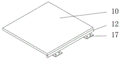
FIG. 2 is a schematic diagram of a second working plate structure of the present invention;
FIG. 3 is a schematic structural view of a first worktable of the present invention;
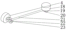
fig. 4 is a schematic structural view of the supporting device of the present invention.
In the figure: 1. a storage cabinet; 2. a file cabinet; 3. a drawer; 4. a first circular table; 5. a universal wheel; 6. a first object placing plate; 7. a second storage plate; 8. a first spin column; 9. a first hinge; 10. a first work plate; 11. a second work plate; 12. a second spin column; 13. a connecting table; 14. a threaded groove; 15. connecting columns; 16. desk legs; 17. a second hinge; 18. a second circular table; 19. a connecting hook; 20. a first snap ring; 21. a support pillar; 22. a second snap ring; 23. and (7) connecting rings.
Detailed Description
In order to facilitate understanding of the present invention, the present invention will be described more fully with reference to the accompanying drawings, in which several embodiments of the present invention are shown, but the present invention can be implemented in different forms, and is not limited to the embodiments described in the text, but rather, these embodiments are provided to make the disclosure of the present invention more thorough and comprehensive.
It will be understood that when an element is referred to as being "secured to" another element, it can be directly on the other element or intervening elements may be present, and when an element is referred to as being "connected" to another element, it can be directly connected to the other element or intervening elements may also be present, as the terms "vertical", "horizontal", "left", "right" and the like are used herein for descriptive purposes only.
Unless defined otherwise, all technical and scientific terms used herein have the same meaning as commonly understood by one of ordinary skill in the art to which this invention belongs, and the use of the term knowledge in the specification of the present invention is for the purpose of describing particular embodiments and is not intended to limit the present invention, and the term "and/or" as used herein includes any and all combinations of one or more of the associated listed items.
Please refer to fig. 1-4, a desk convenient for installation comprises a storage cabinet 1, a first object placing plate 6 is connected to the upper part of the inner wall of the storage cabinet 1 in a sliding manner, a second object placing plate 7 is connected to the lower part of the inner wall of the storage cabinet 1 in a sliding manner, a file cabinet 2 is fixedly connected to the bottom of the storage cabinet 1 and can place work related documents, two drawers 3 are arranged at the front end of the file cabinet 2 and can place the work related documents, universal wheels 5 are fixedly connected to the bottom of the file cabinet 2, a first hinge 9 is fixedly connected to both ends of the front side of the inner bottom wall of the storage cabinet 1, the second hinge 9 is used for rotating the working plate and is accommodated in the storage cabinet 1, a first rotary column 8 is rotatably connected to the middle of the bottom of the first hinge 9, a first working plate 10 is fixedly connected to one end of the first hinge 9 far away from the storage cabinet 1, a second circular truncated cone 18 is, the first snap ring 20 is connected with a connecting hook 19 in a snap-fit manner, the front side of the connecting hook 19 is fixedly connected with a supporting column 21, one end of the supporting column 21, which is far away from the connecting hook 19, is fixedly connected with a connecting ring 23, the connecting ring 23 is connected with a second snap ring 22 in a snap-fit manner, the rear side of the second snap ring 22 is fixedly connected with a first round table 4, the rear side of the first round table 4 is fixedly connected with a file cabinet 2, the front side of the bottom of the first working plate 10 is fixedly connected with two second hinges 17, the first working plate 10 and the second working plate 11 can be folded by the second hinges 17, the middle of the bottom of the second hinges 17 is rotatably connected with a second rotating column 12, one end of the second hinges 17, which is far away from the first working plate 10, is fixedly connected with the second working plate 11, the middle of the bottom of the second working plate 11 is provided with a, four table legs 16 are fixedly connected to the periphery of the bottom of the connecting table 13, and the four table legs 16 are convenient for stabilizing the second working plate 11.
The recess has been opened to 1 inside both ends front side of locker, the spout has been seted up on 1 inner wall both ends upper portion of locker, first 6 sliding connection of putting the thing board in the draw-in groove, the spout has been seted up to 1 inner wall both ends lower part of locker, the second is put thing board 7 sliding connection in the draw-in groove, when the desk is normally used, first put thing board 6 and second put thing board 7 and can place article as required, when the dismouting perhaps shifts, can put thing board 6 and second with first thing board 7 and unload, make things convenient for the workstation to accomodate, place with spare parts such as table leg, can prevent the loss of spare part.
Four universal wheels 5 are fixed respectively in the bottom four corners of filing cabinet 2, make things convenient for the transfer of work table, and universal wheel 5 is provided with locking device, and when normal work, keep the steady of workstation, make the workstation not take place the skew.
One of the two first circular truncated cones 4 is fixedly connected to the front end of the front side of the file cabinet 2, and the other one of the two first circular truncated cones 4 is fixedly connected to the rear end of the front side of the file cabinet 2, so that the first working plate 10 is supported. The middle of the top of the connecting table 13 is provided with a groove, the inner wall of the groove is provided with threads, and the two ends of the connecting column 15 are provided with thread structures, so that the mounting and the dismounting are convenient. The connecting hook 19 is in a three-quarter ring shape, and is conveniently clamped with the first clamping ring 20, and the bottom of the table leg 16 is fixedly connected with a rough gasket for placing the table to slip.
The utility model discloses a concrete operation as follows:
the user is using the utility model discloses before the practicality, utilize universal wheel (5) to push away the workstation to the office space with the desk, then take out first thing board 6 and the second of putting from locker 1 and put thing board 7, then take out table leg 16, spare parts such as spliced pole 13 and spliced pole 15, then take out the workstation under first hinge 8's effect, place behind the level with two hookups 19 hang on first snap ring 20, then it is rotatory to face spliced pole 15 to screw thread draw-in groove 14, make spliced pole 15 and screw thread draw-in groove 14 threaded connection, recycle second hinge 17 and place the level with second workstation 11, recycle the screw thread and keep away from one end threaded connection of second workstation 11 with spliced pole 15 at 13 top intermediate position, the workstation is preceding at the user with complete presentation at this time.
The present invention has been described above with reference to the accompanying drawings, and it is obvious that the present invention is not limited by the above-mentioned manner, if the method and the technical solution of the present invention are adopted, the present invention can be directly applied to other occasions without substantial improvement, and the present invention is within the protection scope of the present invention.
Claims (6)
1. The utility model provides an office table convenient to installation, including locker (1), its characterized in that: the storage cabinet is characterized in that a first storage plate (6) is connected to the upper portion of the inner wall of the storage cabinet (1) in a sliding mode, a second storage plate (7) is connected to the lower portion of the inner wall of the storage cabinet (1) in a sliding mode, a file cabinet (2) is fixedly connected to the bottom of the storage cabinet (1), two drawers (3) are arranged at the front end of the file cabinet (2), universal wheels (5) are fixedly connected to the bottom of the file cabinet (2), first hinges (9) are fixedly connected to the two ends of the front side of the inner bottom wall of the storage cabinet (1), first rotary columns (8) are rotatably connected to the middle of the bottoms of the first hinges (9), a first working plate (10) is fixedly connected to one end, away from the storage cabinet (1), of the first working plate (10), second round tables (18) are fixedly connected to the two ends of the middle of the bottoms, the first clamping ring (20) is connected with a connecting hook (19) in a clamping manner, a supporting column (21) is fixedly connected to the front side of the connecting hook (19), one end, far away from the connecting hook (19), of the supporting column (21) is fixedly connected with a connecting ring (23), the connecting ring (23) is connected with a second clamping ring (22) in a clamping manner, a first round table (4) is fixedly connected to the rear side of the second clamping ring (22), a file cabinet (2) is fixedly connected to the rear side of the first round table (4), two second hinges (17) are fixedly connected to the front side of the bottom of the first working plate (10), a second rotary column (12) is rotatably connected to the middle of the bottom of each second hinge (17), one end, far away from the first working plate (10), of each second hinge (17) is fixedly connected with a second working plate (11), a threaded groove (14) is formed in the middle of, threaded connection has spliced pole (15) in screw thread recess (14), the one end threaded connection that second working plate (11) were kept away from in spliced pole (15) has connection platform (13), four table legs (16) of fixedly connected with all around connect platform (13) bottom.
2. A desk for facilitating installation as claimed in claim 1, wherein: the novel storage cabinet is characterized in that grooves are formed in the front sides of the two ends inside the storage cabinet (1), sliding grooves are formed in the upper portions of the two ends of the inner wall of the storage cabinet (1), the first storage plate (6) is connected in the clamping grooves in a sliding mode, the sliding grooves are formed in the lower portions of the two ends of the inner wall of the storage cabinet (1), and the second storage plate (7) is connected in the clamping grooves in a sliding mode.
3. A desk for facilitating installation as claimed in claim 1, wherein: the four universal wheels (5) are respectively fixed at four corners of the bottom of the file cabinet (2), and locking devices are arranged on the universal wheels (5).
4. A desk for facilitating installation as claimed in claim 1, wherein: one of the two first round tables (4) is fixedly connected to the front end of the front side of the file cabinet (2), and the other one of the two first round tables is fixedly connected to the rear end of the front side of the file cabinet (2).
5. A desk for facilitating installation as claimed in claim 1, wherein: the middle of the top of the connecting table (13) is provided with a groove, the inner wall of the groove is provided with threads, and two ends of the connecting column (15) are provided with thread structures.
6. A desk for facilitating installation as claimed in claim 1, wherein: the connecting hook (19) is in a three-quarter circular ring shape, and the bottom of the table leg (16) is fixedly connected with a rough gasket.
Priority Applications (1)
| Application Number | Priority Date | Filing Date | Title |
|---|---|---|---|
| CN202021528297.6U CN213370602U (en) | 2020-07-29 | 2020-07-29 | Office table convenient to install |
Applications Claiming Priority (1)
| Application Number | Priority Date | Filing Date | Title |
|---|---|---|---|
| CN202021528297.6U CN213370602U (en) | 2020-07-29 | 2020-07-29 | Office table convenient to install |
Publications (1)
| Publication Number | Publication Date |
|---|---|
| CN213370602U true CN213370602U (en) | 2021-06-08 |
Family
ID=76202208
Family Applications (1)
| Application Number | Title | Priority Date | Filing Date |
|---|---|---|---|
| CN202021528297.6U Active CN213370602U (en) | 2020-07-29 | 2020-07-29 | Office table convenient to install |
Country Status (1)
| Country | Link |
|---|---|
| CN (1) | CN213370602U (en) |
-
2020
- 2020-07-29 CN CN202021528297.6U patent/CN213370602U/en active Active
Similar Documents
| Publication | Publication Date | Title |
|---|---|---|
| CN213370602U (en) | Office table convenient to install | |
| CN209950665U (en) | Folding table | |
| CN210058332U (en) | Splicing structure for experiment table | |
| CN213216021U (en) | Wooden office furniture is with combination formula book case convenient to use | |
| CN211323558U (en) | Easily load and unload office equipment | |
| CN211130171U (en) | Combined foldable coffee table | |
| CN212280554U (en) | Extension type primary and secondary cabinet | |
| CN210055091U (en) | Desk capable of turning over board | |
| CN209866101U (en) | Multifunctional chemical experiment iron stand auxiliary device | |
| CN217488111U (en) | Detachable apartment bed of cat ladder | |
| CN208463247U (en) | A kind of desk of scalable lengthening | |
| CN206238751U (en) | A kind of adjustable desk of high inclination degree | |
| CN214279246U (en) | Practical training platform for financial products | |
| CN213429323U (en) | Student apartment bed with folding mosquito net frame | |
| CN217565365U (en) | Foldable environment-friendly cabinet | |
| CN202653586U (en) | Multifunctional tea table | |
| CN219537742U (en) | Multifunctional foldable table | |
| CN211833306U (en) | Multifunctional tutoring table for mental health education | |
| CN210184925U (en) | Manpower resource removes stand convenient to equipment | |
| CN214284307U (en) | Multipurpose indoor foldable flower stand capable of being stored | |
| CN208972899U (en) | A kind of library's portable bookstand | |
| CN215304679U (en) | Wooden flower stand convenient to disassemble and assemble | |
| CN218185609U (en) | Roman umbrella with detachable tea table | |
| CN210169420U (en) | Article placing shelf | |
| CN220236355U (en) | Tea table with tea table foot folding function |
Legal Events
| Date | Code | Title | Description |
|---|---|---|---|
| GR01 | Patent grant | ||
| GR01 | Patent grant |