CN213342482U - Multifunctional monitoring device for power dispatching - Google Patents
Multifunctional monitoring device for power dispatching Download PDFInfo
- Publication number
- CN213342482U CN213342482U CN202022638846.1U CN202022638846U CN213342482U CN 213342482 U CN213342482 U CN 213342482U CN 202022638846 U CN202022638846 U CN 202022638846U CN 213342482 U CN213342482 U CN 213342482U
- Authority
- CN
- China
- Prior art keywords
- frame
- transverse
- longitudinal
- monitoring device
- mounting plate
- Prior art date
- Legal status (The legal status is an assumption and is not a legal conclusion. Google has not performed a legal analysis and makes no representation as to the accuracy of the status listed.)
- Expired - Fee Related
Links
Images


Classifications
-
- Y—GENERAL TAGGING OF NEW TECHNOLOGICAL DEVELOPMENTS; GENERAL TAGGING OF CROSS-SECTIONAL TECHNOLOGIES SPANNING OVER SEVERAL SECTIONS OF THE IPC; TECHNICAL SUBJECTS COVERED BY FORMER USPC CROSS-REFERENCE ART COLLECTIONS [XRACs] AND DIGESTS
- Y02—TECHNOLOGIES OR APPLICATIONS FOR MITIGATION OR ADAPTATION AGAINST CLIMATE CHANGE
- Y02A—TECHNOLOGIES FOR ADAPTATION TO CLIMATE CHANGE
- Y02A50/00—TECHNOLOGIES FOR ADAPTATION TO CLIMATE CHANGE in human health protection, e.g. against extreme weather
- Y02A50/30—Against vector-borne diseases, e.g. mosquito-borne, fly-borne, tick-borne or waterborne diseases whose impact is exacerbated by climate change
Abstract
The utility model provides a multi-functional monitoring device for electric power dispatching, including fixed chassis, the structure of just tearing open in the horizontal direction, the structure of just tearing open in the vertical direction, mosquito collects the frame structure, the drum, the protection casing, the LED lamp ring, the bottom ring, the spacing ring, transparent guard shield, the connection otic placode, panoramic surveillance camera head, top sealing gasket and rubber buffer, the structure of just tearing open in the horizontal direction install in the upper portion of the right side of the structure of just tearing open in the vertical direction; the mosquito collecting frame structure is arranged on the right side of the transverse easy-to-detach frame structure; the protective cover is glued on the upper part of the cylinder; the bottom ring is glued on the lower part of the fixed bottom frame. The transverse frame of the utility model is inserted into the inner side of the T-shaped slot through the T-shaped inserting block, which is beneficial to conveniently mounting and dismounting the longitudinal mounting plate of the transverse frame when in use; the fixing bolts are respectively in threaded connection with the connecting part of the longitudinal plate and the transverse frame and the connecting part of the bottom transverse plate and the side mounting plate, so that the fixing function of the transverse frame is facilitated when the fixing bolt is used.
Description
Technical Field
The utility model belongs to the technical field of power dispatching control, especially, relate to a multi-functional monitoring device that is used for power dispatching.
Background
The method is characterized in that a mode integrated platform is established based on an OMS system, comprehensive real-time data support is provided for daily mode business work of mode personnel, power grid scale statistics and multi-dimensional real-time analysis are realized, important customers and automatic power supply tracing lean management are realized, and more direct, convenient and standard management means is provided for mode economic operation analysis and mode annual analysis. Through the mode integration platform, multi-layer multi-dimensional data support is provided for power grid operation decision.
But the monitoring device of current power scheduling has the inconvenience and dismantles the support, and the inconvenient support is fixed the more problem that influences the effect of making a video recording of mosquito when using night.
Therefore, it is necessary to invent a multifunctional monitoring device for power dispatching.
SUMMERY OF THE UTILITY MODEL
In order to solve the technical problem, the utility model provides a multi-functional monitoring device that is used for electric power scheduling to there is inconvenient dismantling the support in the monitoring device who solves current electric power scheduling, inconvenient fixes the problem that the more influence effect of making a video recording of mosquito when using night to the support. A multifunctional monitoring device for power dispatching comprises a fixed underframe, a transverse conveniently-disassembled frame structure, a longitudinal conveniently-disassembled frame structure, a mosquito collecting frame structure, a cylinder, a protective cover, an LED lamp ring, a bottom ring, a limiting ring, a transparent protective cover, a connecting lug plate, a panoramic monitoring camera, a top sealing gasket and a rubber plug, wherein the transverse conveniently-disassembled frame structure is arranged on the upper part of the right side of the longitudinal conveniently-disassembled frame structure; the mosquito collecting frame structure is arranged on the right side of the transverse easy-to-detach frame structure; the protective cover is glued on the upper part of the cylinder; the bottom ring is glued to the lower part of the fixed underframe; the limiting ring is glued on the upper part of the transparent shield; the transparent shield is arranged at the lower part of the bottom ring; the connecting ear plates are glued at the front end and the rear end of the left side and the right side of the upper part of the transparent shield and are simultaneously connected with the bottom ring screws; the panoramic monitoring camera is arranged on the inner side of the bottom ring, and meanwhile, the screw is arranged on the lower part of the fixed underframe; the transverse easy-to-detach frame structure comprises a transverse frame, a T-shaped insert block, a longitudinal plate, a bottom transverse plate and a fixing bolt, wherein the T-shaped insert block is welded on the left side of the transverse frame; the longitudinal plates are arranged at the front end and the rear end of the left side of the transverse frame; the bottom transverse plate is welded at the lower part of the longitudinal plate.
Preferably, the mosquito collecting frame structure comprises a collecting frame, a net bucket, a metal sheet, a baffle plate and a magnet sheet, wherein the collecting frame is mounted on the right side of the transverse frame through screws; the metal sheet is welded on the right side of the upper part of the collecting frame; the baffle is coupled to the right side of the collecting frame; the cylinder screw is arranged at the upper part of the collecting frame.
Preferably, the longitudinal easy-to-detach frame structure comprises a longitudinal mounting plate, a bolt groove, a bolt hole, a mounting bolt, a side mounting plate and a T-shaped slot, wherein the bolt groove is formed in the lower position of the right side of the longitudinal mounting plate; the bolt hole is formed in the lower position of the longitudinal mounting bolt towards the left side of the mounting plate and is aligned with the middle position of the left side of the bolt groove; the bolt is inserted into the bolt groove and the inner side of the bolt hole; the side mounting plate is welded at the upper part of the right side of the longitudinal mounting plate; the T-shaped slot is arranged on the upper side of the side mounting plate and is arranged on the right side of the longitudinal mounting plate.
Preferably, the transverse frame is inserted into the inner side of the T-shaped slot through the T-shaped inserting block.
Preferably, the fixing bolt is respectively in threaded connection with the connecting position of the longitudinal plate and the transverse frame and the connecting position of the bottom transverse plate and the side mounting plate.
Preferably, the LED lamp ring is glued to the front side and the rear side of the cylinder.
Preferably, the net bucket screw is arranged at the upper part of the inner side of the collecting frame.
Preferably, the magnet sheet is glued on the upper part of the baffle and mutually adsorbed with the metal sheet.
Preferably, the top sealing gasket is glued on the upper part of the longitudinal mounting plate and is arranged on the left side of the upper part of the transverse frame.
Preferably, the rubber plug is inserted into the right side of the inner part of the bolt groove.
Compared with the prior art, the beneficial effects of the utility model are that:
1. the utility model discloses in, horizontal frame peg graft in the inboard of T type slot through T type inserted block, be favorable to when using convenient dismouting on the vertical mounting panel of horizontal frame.
2. The utility model discloses in, fixing bolt respectively threaded connection in the junction of vertical board and horizontal frame and the junction of bottom horizontal board and side mounting panel, be favorable to when using conveniently having played fixed function to horizontal frame.
3. The utility model discloses in, LED lamp ring splice both sides around the drum, be favorable to conveniently attracting the mosquito when using, and avoid the mosquito to rock the monitoring effect that influences power scheduling around panoramic surveillance camera head.
4. The utility model discloses in, net fill screw mounting on the inboard upper portion of collecting the frame, be favorable to when using conveniently playing the mosquito that enters into in the collection frame and shelter from the function to can avoid the mosquito outwards to run out.
5. The utility model discloses in, magnetite piece glue joint on the upper portion of baffle, adsorb each other with the sheetmetal simultaneously, be favorable to conveniently playing the absorption function to the baffle when using to avoid the baffle to open easily on the right side of collecting the frame.
6. The utility model discloses in, top sealing pad glue joint on the upper portion of longitudinal installation board, set up in the upper portion left side of horizontal frame simultaneously, be favorable to avoiding deep into the gap department of horizontal frame and longitudinal installation board when raining to cause the corruption to it.
7. The utility model discloses in, the rubber buffer peg graft on the inside right side in bolt groove, be favorable to playing good guard action to the construction bolt in the bolt groove when using.
Drawings
Fig. 1 is a schematic structural diagram of the present invention.
Fig. 2 is a schematic structural view of the transverse easy-to-detach frame structure of the present invention.
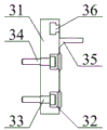
Fig. 3 is a schematic structural view of the vertical easy-to-detach frame structure of the present invention.
Fig. 4 is a schematic structural view of the mosquito collecting rack structure of the present invention.
In the figure:
1. fixing the underframe; 2. a transverse easy-to-disassemble frame structure; 21. a transverse frame; 22. a T-shaped insert block; 23. a longitudinal plate; 24. a bottom transverse plate; 25. fixing the bolt; 3. a longitudinal easy-to-disassemble frame structure; 31. a longitudinal mounting plate; 32. a bolt slot; 33. bolt holes; 34. installing a bolt; 35. a side mounting plate; 36. a T-shaped slot; 4. a mosquito collecting rack structure; 41. a collection frame; 42. a net bucket; 43. a metal sheet; 44. a baffle plate; 45. a magnet sheet; 5. a cylinder; 6. a protective cover; 7. an LED lamp ring; 8. a bottom ring; 9. a limiting ring; 10. a transparent shield; 11. connecting the ear plates; 12. a panoramic surveillance camera; 13. a top seal pad; 14. and a rubber plug.
Detailed Description
The invention is further described below with reference to the accompanying drawings:
example (b):
as shown in figures 1 and 2
The utility model provides a multi-functional monitoring device for electric power dispatching, including fixed chassis 1, the horizontal just tears a structure 2 open, the vertical just tears a structure 3 open, the mosquito collects a structure 4, the drum 5, the protection casing 6, the LED lamp ring 7, the bottom ring 8, the spacing ring 9, transparent guard shield 10, the engaging lug board 11, panorama surveillance camera head 12, top sealing gasket 13 and rubber buffer 14, the horizontal just tears a structure 2 open and installs in the upper portion of the right side of the vertical just tears a structure 3 open; the mosquito collecting frame structure 4 is arranged on the right side of the transverse easy-to-detach frame structure 2; the protective cover 6 is glued on the upper part of the cylinder 5; the bottom ring 8 is glued to the lower part of the fixed underframe 1; the limiting ring 9 is glued on the upper part of the transparent shield 10; the transparent shield 10 is arranged at the lower part of the bottom ring 8; the connecting ear plates 11 are glued to the front and rear ends of the left and right sides of the upper part of the transparent shield 10 and are connected with the bottom ring 8 through screws; the panoramic monitoring camera 12 is arranged on the inner side of the bottom ring 8, and is arranged on the lower part of the fixed underframe 1 through screws; the LED lamp rings 7 are connected to the front side and the rear side of the cylinder 5 in an adhesive mode, mosquitoes can be attracted conveniently when the LED lamp rings are used, the monitoring effect that the electric power dispatching is affected due to the fact that mosquitoes shake around the panoramic monitoring camera 12 is avoided, the top sealing gasket 13 is connected to the upper portion of the longitudinal mounting plate 31 in an adhesive mode and arranged on the left side of the upper portion of the transverse frame 21, and the LED lamp rings can be prevented from penetrating into the gap between the transverse frame 21 and the longitudinal mounting plate 31 to corrode the transverse frame 21 and the longitudinal mounting plate 31 when raining; the transverse easy-to-detach frame structure 2 comprises a transverse frame 21, a T-shaped insert block 22, a longitudinal plate 23, a bottom transverse plate 24 and a fixing bolt 25, wherein the T-shaped insert block 22 is welded on the left side of the transverse frame 21; the longitudinal plates 23 are arranged at the front end and the rear end of the left side of the transverse frame 21; the bottom transverse plate 24 is welded at the lower part of the longitudinal plate 23; the transverse frame 21 is inserted into the inner side of the T-shaped slot 36 through the T-shaped inserting block 22, the longitudinal mounting plate 31 of the transverse frame 21 is convenient to disassemble and assemble when in use, the fixing bolts 25 are respectively in threaded connection with the connecting part of the longitudinal plate 23 and the transverse frame 21 and the connecting part of the bottom transverse plate 24 and the side mounting plate 35, and the transverse frame 21 is convenient to fix when in use.
As shown in fig. 4, in the above embodiment, specifically, the mosquito collecting frame structure 4 includes a collecting frame 41, a net bucket 42, a metal sheet 43, a baffle 44, and a magnet sheet 45, and the collecting frame 41 is mounted on the right side of the transverse frame 21 by screws; the metal sheet 43 is welded at the right side of the upper part of the collecting frame 41; the baffle 44 is axially connected to the right side of the collecting frame 41; the cylinder 5 is mounted on the upper part of the collecting frame 41 through screws; the wire bucket 42 screw installation in the inboard upper portion of collecting frame 41, the convenient mosquito that enters into in the collection frame 41 plays the function of sheltering from when using to can avoid the mosquito outwards to run out, magnetite piece 45 splice on the upper portion of baffle 44, adsorb each other with sheetmetal 43 simultaneously, conveniently play the adsorption efficiency to baffle 44 when using, thereby avoid baffle 44 to open easily on the right side of collecting frame 41.
In the above embodiment, as shown in fig. 3, specifically, the longitudinal easy-to-detach frame structure 3 includes a longitudinal mounting plate 31, a bolt slot 32, a bolt hole 33, a mounting bolt 34, a side mounting plate 35 and a T-shaped slot 36, wherein the bolt slot 32 is opened at a lower position on the right side of the longitudinal mounting plate 31; the bolt hole 33 is arranged at the lower position of the longitudinal mounting bolt 34 towards the left side of the mounting plate 31 and is aligned with the middle position of the left side of the bolt groove 32; the insertion is arranged at the inner sides of the bolt groove 32 and the bolt hole 33; the side mounting plate 35 is welded at the upper position of the right side of the longitudinal mounting plate 31; the T-shaped slot 36 is arranged on the upper side of the side mounting plate 35 and is arranged on the right side of the longitudinal mounting plate 31; the rubber plug 14 is inserted into the right side of the inner part of the bolt groove 32, and can play a good role in protecting the mounting bolt 34 in the bolt groove 32 when in use.
Principle of operation
The utility model discloses in the course of the work, utilize mounting bolt 34 to run through bolt hole 33 to fix longitudinal installation board 31 at the mounted position during use, then insert rubber buffer 14 and fix in bolt groove 32, utilize T type picture peg 22 to insert the inboard of T type slot 36 and assemble after that, then utilize fixing bolt 25 to run through longitudinal plate 23 and horizontal frame 21 threaded connection respectively, and utilize fixing bolt 25 to run through bottom horizontal plate 24 and the fixed of side mounting panel 35 threaded connection realization to horizontal frame 21, utilize panoramic surveillance camera 12 to detect power scheduling surrounding environment at ordinary times, and utilize LED lamp ring 7 to attract the mosquito around panoramic surveillance camera 12 when using night, and the mosquito that enters into collection frame 41 from the net fill 42 can not run out to the outside easily, so that can reduce the quantity of mosquito around.
Utilize technical scheme, or technical personnel in the field are in the utility model discloses under technical scheme's the inspiration, design similar technical scheme, and reach above-mentioned technological effect, all fall into the utility model discloses a protection scope.
Claims (10)
1. The utility model provides a multi-functional monitoring device that is used for power scheduling, its characterized in that, this multi-functional monitoring device that is used for power scheduling, including fixed chassis (1), transversely just tear a structure (2) open, vertically just tear a structure (3) open, frame structure (4) are collected to the mosquito, drum (5), protection casing (6), LED lamp ring (7), bottom ring (8), spacing ring (9), transparent guard shield (10), engaging lug board (11), panorama surveillance camera head (12), top sealed pad (13) and rubber buffer (14), transversely just tear a structure (2) open and install on the upper portion of the right side of vertically just tearing a structure (3) open; the mosquito collecting frame structure (4) is arranged on the right side of the transverse easy-to-detach frame structure (2); the protective cover (6) is glued on the upper part of the cylinder (5); the bottom ring (8) is glued to the lower part of the fixed underframe (1); the limiting ring (9) is glued on the upper part of the transparent shield (10); the transparent shield (10) is arranged at the lower part of the bottom ring (8); the connecting ear plates (11) are glued to the front and rear ends of the left and right sides of the upper part of the transparent shield (10) and are connected with the bottom ring (8) through screws; the panoramic monitoring camera (12) is arranged on the inner side of the bottom ring (8), and is installed on the lower part of the fixed underframe (1) through screws; the transverse easy-to-detach frame structure (2) comprises a transverse frame (21), a T-shaped insert block (22), a longitudinal plate (23), a bottom transverse plate (24) and a fixing bolt (25), wherein the T-shaped insert block (22) is welded on the left side of the transverse frame (21); the longitudinal plates (23) are arranged at the front end and the rear end of the left side of the transverse frame (21); the bottom transverse plate (24) is welded at the lower part of the longitudinal plate (23).
2. The multifunctional monitoring device for power dispatching of claim 1, wherein the mosquito collecting frame structure (4) comprises a collecting frame (41), a net bucket (42), a metal sheet (43), a baffle plate (44) and a magnet sheet (45), and the collecting frame (41) is mounted on the right side of the transverse frame (21) through screws; the metal sheet (43) is welded on the right side of the upper part of the collecting frame (41); the baffle (44) is coupled to the right side of the collecting frame (41); the cylinder (5) is mounted on the upper part of the collecting frame (41) through screws.
3. The multifunctional monitoring device for power dispatching of claim 1, wherein the longitudinal easy-to-detach frame structure (3) comprises a longitudinal mounting plate (31), a bolt groove (32), a bolt hole (33), a mounting bolt (34), a side mounting plate (35) and a T-shaped slot (36), the bolt groove (32) is arranged at the lower right position of the longitudinal mounting plate (31); the bolt hole (33) is arranged at the lower position of the left side of the longitudinal mounting plate (31) and is aligned with the middle position of the left side of the bolt groove (32); the mounting bolt (34) is inserted into the inner sides of the bolt groove (32) and the bolt hole (33); the side mounting plate (35) is welded at the upper position of the right side of the longitudinal mounting plate (31); the T-shaped slot (36) is arranged on the upper side of the side mounting plate (35) and is arranged on the right side of the longitudinal mounting plate (31).
4. The multifunctional monitoring device for power dispatching of claim 3, characterized in that the transverse frame (21) is inserted inside the T-shaped slot (36) through the T-shaped insertion block (22).
5. The multifunctional monitoring device for power dispatching of claim 3, characterized in that the fixing bolts (25) are respectively screwed at the connection of the longitudinal plate (23) and the transverse frame (21) and the connection of the bottom transverse plate (24) and the side mounting plate (35).
6. The multifunctional monitoring device for power dispatching of claim 1, characterized in that the LED lamp ring (7) is glued on the front and back sides of the cylinder (5).
7. The multifunctional monitoring device for power dispatching of claim 2, wherein the net bucket (42) is screw-mounted on the upper inner side of the collecting frame (41).
8. The multifunctional monitoring device for power dispatching of claim 2, wherein the magnet sheet (45) is glued to the upper portion of the baffle (44) and is attracted to the metal sheet (43).
9. The multifunctional monitoring device for power dispatching of claim 1, characterized in that the top gasket (13) is glued to the upper part of the longitudinal mounting plate (31) and is arranged on the left side of the upper part of the transverse frame (21).
10. The multifunctional monitoring device for power dispatching of claim 3, characterized in that the rubber stopper (14) is inserted at the right side of the inside of the bolt groove (32).
Priority Applications (1)
| Application Number | Priority Date | Filing Date | Title |
|---|---|---|---|
| CN202022638846.1U CN213342482U (en) | 2020-11-16 | 2020-11-16 | Multifunctional monitoring device for power dispatching |
Applications Claiming Priority (1)
| Application Number | Priority Date | Filing Date | Title |
|---|---|---|---|
| CN202022638846.1U CN213342482U (en) | 2020-11-16 | 2020-11-16 | Multifunctional monitoring device for power dispatching |
Publications (1)
| Publication Number | Publication Date |
|---|---|
| CN213342482U true CN213342482U (en) | 2021-06-01 |
Family
ID=76078482
Family Applications (1)
| Application Number | Title | Priority Date | Filing Date |
|---|---|---|---|
| CN202022638846.1U Expired - Fee Related CN213342482U (en) | 2020-11-16 | 2020-11-16 | Multifunctional monitoring device for power dispatching |
Country Status (1)
| Country | Link |
|---|---|
| CN (1) | CN213342482U (en) |
-
2020
- 2020-11-16 CN CN202022638846.1U patent/CN213342482U/en not_active Expired - Fee Related
Similar Documents
| Publication | Publication Date | Title |
|---|---|---|
| CN203038588U (en) | Light-emitting diode (LED) display unit box body and LED display modules thereof | |
| CN213342482U (en) | Multifunctional monitoring device for power dispatching | |
| CN211151134U (en) | Low-voltage switch cabinet easy to dissipate heat and maintain | |
| CN205280786U (en) | Dustproof and waterproof ammeter case of easily installing | |
| CN212259528U (en) | Outdoor cabinet convenient to it is waterproof dirt-proof | |
| CN220537247U (en) | Emergency power supply device and safety protection shell thereof | |
| CN220820807U (en) | Smoke sensor with dust entering prevention function | |
| CN205252751U (en) | Prefilter framed bent that shock -resistant V -arrangement was arranged | |
| CN218412738U (en) | Rail transit display device and rail transit live-line detection display system | |
| CN218410245U (en) | Exhaust air pipe system | |
| CN108697034A (en) | A kind of network data cabinet with wind speed measurement function | |
| CN208459494U (en) | A kind of novel and multifunctional electric power detector | |
| CN214209760U (en) | Follow-on detachable concatenation type air cleaner | |
| CN220171725U (en) | Can assemble fire control propaganda cabinet | |
| CN219811240U (en) | Hydropower station fault alarm device | |
| CN210608089U (en) | Power distribution monitoring device convenient to install and detach | |
| CN211702680U (en) | Outdoor monitoring box | |
| CN217765063U (en) | Building site raise dust monitor that sensitivity is high | |
| CN211181555U (en) | Political affairs publicity column is thought in dual-purpose open air of fine and rain | |
| CN214044687U (en) | Wall-hanging JXF block terminal | |
| CN211179737U (en) | Outdoor air quality real-time display device | |
| CN219965941U (en) | Totally-enclosed coal bunker air curtain fume chamber with filtering capability | |
| CN212849690U (en) | Easy dismouting cable crane span structure | |
| CN209857312U (en) | Industrial ventilation equipment | |
| CN218772107U (en) | Multichannel emergency broadcasting adapter |
Legal Events
| Date | Code | Title | Description |
|---|---|---|---|
| GR01 | Patent grant | ||
| GR01 | Patent grant | ||
| CF01 | Termination of patent right due to non-payment of annual fee | ||
| CF01 | Termination of patent right due to non-payment of annual fee |
Granted publication date: 20210601 Termination date: 20211116 |