CN213341676U - High-efficiency convenient charger - Google Patents
High-efficiency convenient charger Download PDFInfo
- Publication number
- CN213341676U CN213341676U CN202021726642.7U CN202021726642U CN213341676U CN 213341676 U CN213341676 U CN 213341676U CN 202021726642 U CN202021726642 U CN 202021726642U CN 213341676 U CN213341676 U CN 213341676U
- Authority
- CN
- China
- Prior art keywords
- charger
- electrode
- cambered surface
- mobile phone
- convenient
- Prior art date
- Legal status (The legal status is an assumption and is not a legal conclusion. Google has not performed a legal analysis and makes no representation as to the accuracy of the status listed.)
- Active
Links
Images


Abstract
The utility model provides a high-efficient convenient charger, characterized by: the outer surfaces of the charger (1) and the mobile phone shell (2) are provided with at least one conductive binding post (3), or electrode plate (4), or cambered surface electrode (18), or mobile phone finger ring (32), and the binding post (3), or electrode plate (4), or cambered surface electrode (18), or mobile phone finger ring (32) is electrically connected with the data connection line (11) or the USB (universal serial bus) interface. The utility model discloses a charging efficiency of high-efficient convenient charger and cell-phone shell is the same with the efficiency of wired charger, and is with low costs, and external no electromagnetic radiation because it is bigger to charge the regional area of placing, and it is convenient at will to use.
Description
Technical Field
The utility model relates to a communication and electrical apparatus field and cell-phone field of charging, concretely relates to household electrical appliances charger and cell-phone charger, treasured and the converter that charges charge.
Background
Wireless charging is more convenient than wired charging, but wireless charger has more low charging efficiency than wired charger, and the shells of household appliances such as mobile phones have certain thickness, can increase wireless transmission distance, and this influences the efficiency of wireless charger, and the charging efficiency is lower for the wall thickness is bigger, and wireless charging efficiency is about 70% -75% at present, and wireless charger manufacturing process is complicated, and the cost is very high. Although the wireless charging is divided into two parts, the transmitter and the receiver are not separated too far from each other, otherwise the charging efficiency is greatly reduced or even charging is impossible, and therefore, contact charging is also performed. Because the current wireless charging efficiency is low, the price is high, the structure is complex and the fault is easy to occur, the wireless charger is difficult to popularize.
Disclosure of Invention
The utility model discloses aim at reaching the convenient to use effect of wireless charger with current wired charger, charging efficiency still remains the high efficiency of wired charger simultaneously to the electromagnetic radiation of wireless charging has been eliminated.
Technical scheme
The utility model provides a technical scheme that its technical problem adopted is:
the utility model provides a high-efficient convenient charger, characterized by: at least one conductive binding post 3 or electrode plate 4 or cambered surface electrode 18 is arranged on the surface of the shell of the convenient charger 1, and the binding post 3 or electrode plate 4 or cambered surface electrode 18 is electrically connected with the data connecting wire 11 or the USB (universal serial bus) interface 16.
Further, the total number of the conductive terminals 3 or the electrode plates 4 or the cambered surface electrodes 18 is at least 2, and the conductive terminals or the electrode plates or the cambered surface electrodes are respectively and electrically connected with the positive electrode and the negative electrode of the USB (universal serial bus) interface 16.
The utility model provides a high-efficient convenient treasured that charges, characterized by: the USB interface comprises a storage battery 25, a control circuit board 29 and a USB interface 16, wherein at least one conductive binding post 3 or electrode plate 4 or cambered surface electrode 18 is arranged on the outer surface of the storage battery, and the binding post 3 or electrode plate 4 or cambered surface electrode 18 is electrically connected with the positive electrode and the negative electrode of the USB interface 16 and/or the storage battery 25.
The utility model provides a high-efficient convenient charger, characterized by: the outer surface of the mobile phone charger consisting of the power plug 27, the control circuit board 29 and the USB interface 16 is provided with at least two conductive binding posts 3 or electrode plates 4 or cambered surface electrodes 18 in total number, and the conductive binding posts 3 or electrode plates 4 or cambered surface electrodes 18 are electrically connected with the output positive and negative electrodes of the charger 1 conveniently.
Further, a storage battery 25 is arranged in the convenient charger 1, and the positive and negative electrodes of the storage battery 25 are electrically connected with the conductive binding post 3 or the electrode plate 4 or the cambered surface electrode 18 and/or the USB interface 16.
Further, the USB interface 16 is in one or a combination of the following forms:
1) the USB interface 16 is a USB interface of standard USB1.0, 2.0, 3.0 or more versions;
2) the USB interface 16 is a mini-USB interface;
3) the USB interface 16 is a micro-USB interface;
4) the USB interface 16 is a Type interface;
5) the USB interface 16 is a Type-C interface;
6) the USB interface 16 is an A, B, C, AB type USB interface derived from the aforementioned interface;
7) the USB interface 16 is a female socket or a male head of the interface;
8) the USB interface 16 is a universal interface with a mobile phone interface of a mobile phone manufacturer;
9) the USB interface 16 is a data connecting line 11 or a power plug 27;
10) the USB interface 16 is another form of interface that is being developed.
Further, the binding post 3 or the electrode plate 4 or the cambered surface electrode 18 is connected with a flexible body or an elastic sheet or a spring.
Further, at least one strong magnet or magnet guide plate is arranged inside or on the side face of the efficient convenient charger 1 and the mobile phone shell 2.
Further, the efficient convenient charger 1 is provided with a connecting structure, so that the efficient convenient charger is conveniently and fixedly connected with an automobile or a mobile phone.
Further, the electrode plate 4 or the arc electrode 18 is of a concentric circle structure or a split structure, and the overall shape of the electrode plate 4 or the arc electrode 18 is a circle, a rectangle, a fish, a eight diagrams shape, a sun, a moon, a runway shape, a polygon or a closed artistic curve shape or an artistic modeling.
Further, the terminal 3 or the electrode plate 4 or the cambered surface electrode 18 is connected with the charger 1 or the mobile phone shell 2 in a sliding mode.
Further, the binding post 3 or the electrode plate 4 or the cambered surface electrode 18 is connected with the indicator light 9 and the control circuit board 29.
Advantageous effects
The utility model has the advantages that:
1. is convenient to use. The utility model discloses the using-way with wireless charger is the same, has broken away from the constraint of cotton rope, and the use of charging need not the plug, along with taking along with putting, because the charging electrode board is more big than the area of the flexible post of present additional magnet, and it is bigger to charge to place regional area, even place a lot of also can normally charge in the position incline, uses convenient freely more at will. The mobile phone with the current output voltage of 5V and 12V full voltage, the vehicle-mounted electric appliance and the like can be safely and conveniently charged.
2. High efficiency and energy saving. The utility model discloses set up the contact terminal or the wiring board that have that conveniently charges at power charger end and cell-phone USB kneck, still there is the contact converter that charges in essence, therefore power transmission efficiency does not have the loss almost, for wired charger charge the same efficiency, compare wireless charger energy-conserving power saving 20-30% of present, compare wireless charger and place the position more inclined charging efficiency lower more, the utility model discloses a make things convenient for the charger to place the position no matter how the incline as long as can charge charging efficiency all be with the same efficient of wired charger.
3. The cost is low. The utility model discloses the complicated wireless transmission components and parts such as transmitting coil, receiving coil, transmitting circuit board, receiving circuit board of wireless charger have been saved, make the cost reduce by a wide margin.
4. There is no electromagnetic radiation. The utility model discloses a terminal or the wiring board that have the contact are connected, can not produce electromagnetic radiation harm to the outside.
5. And (4) safety. The utility model discloses utilize the power cord that original power plug was drawn forth, output voltage is only about 5-20 volts, is less than 36 volts safe voltage power consumption requirements, and the improper can cause the electric shock danger, does not have electromagnetic radiation, and is very safe.
6. Can be charged with large current. Because the area of electrode plate is big, can set up a plurality of electrically conductive pogo pins and cambered surface electrode, can support the hypervelocity of 5A100W to self can dispel the heat fast.
Drawings
The present invention will be further explained with reference to the drawings and examples.
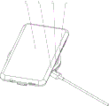
Fig. 1 is a schematic perspective view of the convenient charger with concentric electrode plate structure of the present invention.
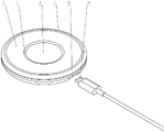
Fig. 2 is a schematic view of the internal three-dimensional structure of the convenient charger of the present invention.
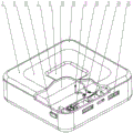
Fig. 3 is a schematic view of a back three-dimensional structure of a mobile phone case used with the charger of the present invention.
Figure 4 is a schematic view of the internal cross-sectional structure of a mobile phone housing used with the charger of the present invention.
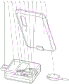
Fig. 5 is a schematic view of the three-dimensional structure of the mobile phone charging state in the use of the charger and the mobile phone shell.
Fig. 6 is a schematic perspective view of the portable charger with concentric electrode plates arranged in different heights according to the present invention.
Fig. 7 is a schematic perspective view of the mobile phone case with circular arc electrode plate of the present invention.
Fig. 8 is a schematic perspective view of the charger with the positive and negative fish-shaped electrode plates according to the present invention.
Fig. 9 is a schematic perspective view of the convenient charger with telescopic concentric electrode plates according to the present invention.
FIG. 10 is a convenient charger with a battery of the present invention;
fig. 11 is a convenient charger integrated with a mobile phone charger of the present invention
Fig. 12 is a convenient charger of the present invention, which is integrated with a mobile phone charger.
In the figure, 1-charger, 2-mobile phone shell, 3-conductive column, 4-electrode plate, 5-shell, 6-inner electrode plate, 7-isolation strip, 8-outer electrode plate, 9-wiring plug board in USB interface, 10-USB male head (interface), 11-data connection line, 12-wiring piece, 13-conducting wire, 14-insulating film, 15-electrode connection piece, 16-USB female seat (interface), 17-mobile phone, 18-cambered surface electrode, 19-outer gland, 20-expansion spring, 21-charger, 22-USB interface, 23-USB Type-C female seat, 24-digital display module, 25-storage battery, 26-switch, 27-plug electrode, 28-control circuit board and 29-film.
Detailed Description
The present invention will be described in further detail with reference to the accompanying drawings.
The first embodiment is as follows:
as shown in fig. 1 and fig. 2, the present invention is a high-efficiency convenient charger. The mobile phone charger generally comprises a plug electrode, a shell, an internal transformer, an inductor, a capacitor, a PCB circuit board and a USB female socket on one side, 110 volt or 220 volt commercial electricity can be converted into direct current through the internal control circuit board to provide a safe power supply for the outside, positive and negative electrodes output by the mobile phone charger are connected with positive and negative terminals of the USB female socket 16, and the mobile phone can be powered through a data line. Along with scientific and technological development and technological progress, the interface form of cell-phone charger and data transmission's USB universal serial bus has experienced the change of 1.0, 2.0, 3.0 version, later developed more exquisite mini USB and micro USB interface and the powerful TYPE-C interface of function, the difference of A TYPE, B TYPE, AB TYPE and C TYPE in addition, be divided into female seat and public head on the USB interface hardware, each TYPE of USB interface principle is the same, for the convenience of expression, the utility model discloses use disc cell-phone charger and typical USB2.0, USB TYPE-C TYPE interface to explain as the example. For distinguishing the mobile phone charger, the utility model discloses a novel charger is called convenient charger. Two electrode plates 4 are arranged on a shell 5 of a convenient charger 1, for a circular charger, one implementation structure of the two electrode plates 4 is that an inner electrode plate 4 and an outer electrode plate 4 are arranged into a concentric circle structure, namely, an inner circular electrode plate 6 arranged inside and an annular outer ring electrode plate 8 arranged outside, and a separation belt 7 is arranged between the inner electrode plate 6 and the outer ring electrode plate 8. The isolation strip 7 is an insulating material, such as plastic. The electrode plate 4, the inner electrode plate 6 and the outer ring electrode plate 8 are made of materials with good electric conduction, such as copper, silver, gold, stainless steel, aluminum, iron, zinc and tin, or coating materials with the surfaces plated with the above metals. The upper surface of the shell 5 is provided with a circular groove and a circular ring groove which are respectively embedded with an inner polar plate 6 and an outer polar plate 8.
As shown in fig. 2, different types of USB female sockets 16 can be disposed on the lower shell of the convenient charger shell 5, in order to make the metal shell of the USB female socket 16 hidden in the internal structure view clearly visible, a patch board 9 is disposed in the USB female socket 16, the patch board 9 is provided with corresponding conductive wires according to different USB connector standards, a lug 12 is respectively led out from two conductive wires correspondingly charged on the patch board 9, a lead 13 is welded or plugged on the lug 12, the lead 13 is electrically connected with the inner polar plate 6 and the outer polar plate 8, for each charger and mobile phone to be able to be used commonly, the connection positions of the lug 12 connected with the charging positive and negative poles on the patch board 9 and the inner polar plate 6 and the outer polar plate 8 should be set in a uniform direction, for example, the lug 12 connected with the charging positive pole of the patch board 9 is connected with the inner polar plate 6, and the lug 12 connected with the charging negative pole on the patch board 9 is connected with the outer polar, after the wiring direction is unified, any two chargers 1 and the mobile phone shell 2 can be used in a matched mode to charge correctly. The mobile phone charger can be connected with a USB TYPE-C female seat 16 convenient for the charger through a TYPE-C male head 10 of a data connecting line 11, so that the inner polar plate 6 and the outer polar plate 8 are in a standby state, and the mobile phone can be charged at any time.
As shown in fig. 3, for the utility model discloses a convenient cell-phone shell that charges, the inside shape of cell-phone shell 2 coincide with the cell-phone outline, can overlap in the cell-phone outside, protection cell-phone. Use the country made hua to be the cell-phone shell as an example, 2 outside central authorities of cell-phone shell put to set up and lead electrical pillar 3, lead electrical pillar 3 and set up the center post that can stretch out and draw back as the center, lead electrical pillar 3 at ordinary times by the ejecting center post of spring. Set up the female seat 16 of USB TYPE-C in the USB socket 22 of the bottom of cell-phone shell 2, set up the wiring picture peg in the female seat 16 of USB TYPE-C, can be connected with the public head 10 of USB TYPE-C of data connection line 11. As shown in fig. 4, the wiring inserting plate 9 of the female seat 16 of USB TYPE-C is provided with a built-in male head 10 of USB TYPE-C through wire connection inside the mobile phone shell 2, the built-in male head 10 of USB TYPE-C can be inserted into the female seat of USB TYPE-C at the tail of the mobile phone when the mobile phone shell 2 is sleeved outside the mobile phone, and the wiring inserting plate 9 of the female seat 16 of USB TYPE-C at the bottom of the mobile phone shell 2 is connected with the female seat of USB TYPE-C at the tail of the mobile phone. The mobile phone charger or the 12V vehicle-mounted power supply and the male 10 of USB TYPE-C of data connecting line 11 insert in the female seat 16 of USB TYPE-C of cell-phone shell 2 bottom just can directly charge, use the 11 both ends of data connecting line to insert respectively in the female seat 16 of USB TYPE-C and the female seat of computer USB2.0 of cell-phone shell 2 bottom just can transmit data.
Two electrode connection pieces 15 are arranged inside the mobile phone shell 2, one ends of the two electrode connection pieces 15 are respectively connected with charging positive and negative electrode connection pieces on the USB TYPE-C female seat 16, and the other ends of the two electrode connection pieces 15 are connected with the conductive column 3. The conductive column 3 is provided with a telescopic central column as the center, and the conductive column 3 is ejected out of the central column by a spring at ordinary times. An insulating film 14 is also applied to the interior of the handset housing 2 to separate the electrode connection pads 15 and the conductive posts 3 from the handset.
As shown in fig. 5, during charging, the mobile phone 17 and the mobile phone case 2 sleeved outside are placed on the portable charger 1 together, the central column between the two conductive columns 3 contacts the inner polar plate 6 and the outer polar plate 8 of the two electrode plates 4 on the portable charger 1, and the mobile phone 17 can be charged when the charging circuit is switched on.
The aforementioned electrode connection pieces 15 may be replaced with wires.
As shown in fig. 6, the heights between the inner electrode plate 6 and the outer ring electrode plate 8 of the two electrode plates 4 can be set on different planes, i.e. one is higher and the other is lower, e.g. the middle inner electrode plate 6 is lower than the outer ring electrode plate 8, so that the negative and positive electrodes can be prevented from being connected reversely.
As shown in fig. 7, the conductive column 3 may be replaced by a convex arc electrode 18, or the tail end of the electrode connecting sheet 15 is a circular arc electrode 18 protruding from the middle, when the mobile phone shell 2 is placed on the portable charger 1, the two convex arc electrodes 18 of the mobile phone shell 2 contact the inner electrode plate 6 and the outer electrode plate 8 of the two electrode plates 4 on the portable charger 1, and the mobile phone can be charged when the charging circuit is turned on.
The cambered electrode 18 can be connected with a flexible film and/or a spring sheet so as to enhance the elasticity of the cambered electrode 18.
The electrode plate 4 may have a separate structure, instead of the concentric structure.
As shown in fig. 8, the upper surface of the circular charger is provided with two separate male and female fish-shaped electrode plates 4 separated by a separator 7. The isolation strip 7 is connected with the surface of the housing, and can be regarded as two electrode plates 4 which are separated from each other by a certain distance and are arranged on the upper surface of the housing 5.
The electrode plate 4 can be connected with the charger 1 or the mobile phone shell 2 in a sliding mode, and the back of the electrode plate 4 is connected with the spring and can stretch and float up and down.
As shown in fig. 9, the utility model discloses a convenient charger with a built-in telescopic electrode plate. Use the disc to make things convenient for charger 1 and USBType-C Type interface as the example, the utility model discloses set up circular recess and ring groove at the upper surface that makes things convenient for 1 shell 5 of charger, inlay respectively and go into interior polar plate 6 and outer loop polar plate 8, interior polar plate 6 and outer loop polar plate 8 are concentric circle structure, and interior polar plate 6, outer loop polar plate 8 are electrically conductive good material. The heights of the inner pole plate 6 and the outer ring pole plate 8 are different, the inner pole plate 6 is lower than the outer ring pole plate 8, an outer gland 19 is arranged on the outer ring pole plate 8, the outer ring pole plate 8 is fixed on the shell 5, a separation belt 7 is arranged between the inner pole plate 6 and the outer ring pole plate 8, and the separation belt 7 is made of insulating materials such as plastics. The outer edge of the isolation belt 7 is pressed on the outer ring polar plate 8 and is arranged in the inner hole of the shell 5, the outer ring polar plate 8 is fixed, and the inner edge of the isolation belt 7 is pressed to limit the inner polar plate 6 to be lower than the outer ring polar plate 8. The inner polar plate 6 can slide and stretch in the inner hole of the isolation belt 7, and the spring 20 is arranged at the bottom of the inner polar plate 6 so as to keep the inner polar plate 6 to form good electric contact with the conductive column 3 or the cambered surface electrode 18 or the electrode with other shapes on the mobile phone shell 2.
Different TYPEs of USB female sockets 16 can be provided on the lower shell of the housing 5 of the portable charger 1, the USB female sockets 16 being of TYPE-C TYPE in the figure. The positive and negative terminal lugs 12 of the USB TYPE-C female seat are respectively connected with the inner polar plate 6 and the outer polar plate 8 by leads 13.
During charging, the USB TYPE-C male connector of the data connecting line 11 for the mobile phone charger is inserted with the USB TYPE-C female seat in the convenient charger 1, and the inner polar plate 6 and the outer annular polar plate 8 on the shell 5 of the convenient charger 1 are powered. When the mobile phone shell 2 with two conductive columns 3 or arc electrodes 18 at the bottom and the mobile phone inside are placed on the convenient charger 1, the power supply is switched on to charge the mobile phone. The two electrode plates 4 of the convenient charger can be in two or more rectangles besides a circle and a circular ring, and the appearance of the convenient charger can be square, long strip or other artistic shapes.
Example two:
as shown in fig. 10, for the convenient charger with the storage battery of the present invention, the mobile phone can be charged by the storage battery inside, so that the charging is convenient for traveling, and the charger can also be called as a convenient charger in a popular way. Take square treasured that charges as an example, the utility model discloses set up square groove and square annular groove at the casing upper surface that makes things convenient for charger shell 5, inlay respectively into square inner polar plate 6 and square annular outer loop polar plate 8. The electrode plates are arranged in a zigzag structure shown in the figure, namely a square inner electrode plate 6 arranged inside and a square annular outer electrode plate 8 arranged outside, and a separation belt 7 is arranged between the inner electrode plate 6 and the outer electrode plate 8. The heights of the inner polar plate 6 and the outer polar plate 8 can be the same or different, preferably, the height of the inner polar plate 6 is lower than that of the outer polar plate 8, and the arrangement is proper, so that the reverse connection of the anode and cathode directions of a power supply can be avoided. The housing 5 and the isolation strip 7 are of an insulating material, such as plastic. The electrode plate 4, the inner electrode plate 6 and the outer ring electrode plate 8 are made of materials with good electric conduction.
The storage battery 25 is arranged in the lower shell of the charger shell 5, the positive and negative electrodes of the storage battery 25 are respectively and electrically connected with the inner polar plate 6 and the outer ring polar plate 8 through the leads 13, in order to realize that all chargers and mobile phones can be used commonly, the connection positions of the positive and negative electrodes of the storage battery 25 and the inner polar plate 6 and the outer ring polar plate 8 are arranged according to a uniform direction, for example, the positive electrode of the storage battery 25 is connected with the inner polar plate 6, the negative electrode of the storage battery 25 is connected with the outer ring polar plate 8, and after the connection directions of the positive electrode and the negative electrode are unified.
Different TYPEs of USB female seats 16, such as a USB2.0 female seat 16 and a USB TYPE-C female seat 23 or a micro-USB female seat, are arranged in the USB socket 22 of the lower shell and are respectively and electrically connected with the positive electrode and the negative electrode of the storage battery 25. The mobile phone charger can be connected with the positive and negative electrodes of the storage battery 25 through the TYPE-C female socket 23 by using a data line to charge the storage battery 25. The switch 26 arranged on the side surface of the lower shell can control the digital display module 24 to display the electric quantity of the storage battery. The charged storage battery 25 can be charged externally through the USB2.0 female socket 16, and one or more mobile phones can be charged simultaneously through the data line. Under the condition that the storage battery 25 is not electrified, the data line and the mobile phone charger can be connected with the TYPE-C female seat 23, the TYPE-C female seat 23 supplies power to the inner polar plate 6 and the outer annular polar plate 8 on the shell 5 of the convenient charger 1, and when the mobile phone shell 2 with the two conductive columns 3 or the cambered surface electrodes 18 at the bottom of the mobile phone is placed on the convenient charger 1, the mobile phone charger can be connected to charge the mobile phone.
Example three:
as shown in fig. 11, it is a convenient charger integrated with a mobile phone charger of the present invention. The mobile phone charger generally comprises a plug electrode 27, a shell 5, a control circuit board 28 consisting of an internal transformer, an inductor, a capacitor, a PCB circuit board and other components, and a USB female socket 16 on one side, can convert a 110V or 220V commercial power or a 12V vehicle-mounted power supply into 5V or 9V direct current through an internal control circuit to provide a safe power supply for the outside, and the positive and negative electrodes output by the mobile phone charger are also connected with positive and negative electrode connecting terminals of the USB female socket 16. The data connection line 11 can be inserted to supply power to the outside. Two conductive electrode plates 4 are arranged on the upper surface of a shell 5 of the mobile phone charger, one electrode plate 4 is positioned in the middle of the mobile phone charger, and the other electrode plate 4 is positioned at one end of the mobile phone charger, which is close to a plug electrode 27. The two electrode plates 4 are electrically connected with the output anode and cathode of the mobile phone charger to form the convenient charger 1. In order to facilitate the charging of the mobile phone, the middle electrode plate 4 is connected with the positive electrode of the mobile phone charger, the electrode plate 4 near one end of the plug electrode 27 is connected with the negative electrode of the mobile phone charger, correspondingly, the bottom of the matched mobile phone shell 2 is provided with three conductive posts 3, the conductive posts 3 are preferably telescopic conductive posts with springs, the position of the middle conductive post 3 corresponds to that of the middle electrode plate 4, the two conductive posts 3 at two sides correspond to the electrode plate 4 near one end of the plug electrode 27, the middle conductive post 3 is connected with the positive electrode of the mobile phone battery, and the conductive posts 3 at two sides are connected with the negative electrode of the mobile phone battery.
When the cell-phone with cell-phone shell 2 was put and is charged on making things convenient for charger 1, it can all guarantee that the anodal conducting post 3 in the middle of cell-phone shell 2 is connected with the anodal polar plate 4 in the middle of making things convenient for charger 1 to place the cell-phone from two directions about from, guarantees simultaneously that the negative pole of cell-phone shell 2 both sides is led one of electrical post 3 and is connected with the negative pole polar plate 4 that makes things convenient for charger 1 to be close to plug electrode 27 one end, correctly charges to the cell-phone.
As shown in fig. 12, it is a convenient charger of the present invention, which is integrated with a mobile phone charger and has three pole plates. Three conductive electrode plates 4 are arranged on the upper surface of a shell 5 of the mobile phone charger, one electrode plate 4 is positioned in the middle of the mobile phone charger, the other two electrode plates 4 are positioned at two ends of the mobile phone charger, and the electrode plates 4 are electrically connected with the output positive electrode and the output negative electrode of the mobile phone charger to form the convenient charger 1. In order to facilitate the charging of the mobile phone, the middle electrode plate 4 is connected with the positive electrode of the mobile phone charger, the middle height is lower than the height of the electrode plates 4 at the two sides, the electrode plates 4 at the two ends are connected with the negative electrode of the mobile phone charger, correspondingly, two cambered surface electrodes 8 are arranged at corresponding positions at the bottom of the matched mobile phone shell 2, the cambered surface electrodes 8 are conductive metal electrodes with artistic modeling, for example, the middle cambered surface electrode 8 is round with the sun, and the cambered surface electrodes 8 at the sides are crescent, so that the aesthetic feeling is enhanced. The position of the middle circular arc-shaped electrode 8 is correspondingly contacted with the position of the middle electrode plate 4, the position of the side crescent arc-shaped electrode 8 is correspondingly contacted with the electrode plates 4 at the two ends, the middle circular arc-shaped electrode 8 is connected with the anode of the mobile phone battery, and the side crescent arc-shaped electrode 8 is connected with the cathode of the mobile phone battery.
When the cell-phone with cell-phone shell 2 was put and is charged on making things convenient for charger 1, it can all guarantee that the circular cambered surface electrode 8 of positive pole in the middle of cell-phone shell 2 is connected with the anodal electrode plate 4 of the centre of making things convenient for charger 1 to place the cell-phone from two directions about from, guarantees simultaneously that the negative pole crescent cambered surface electrode 8 of cell-phone shell 2 side is connected with a negative pole electrode plate 4 of making things convenient for charger 1 side, correctly charges to the cell-phone.
The USB2.0 female socket is arranged in the USB socket 22 on the side surface of the charger 1, and the mobile phone can be charged by the data connecting wire 11.
Under the condition that there is not commercial power socket, and when only the computer, can be connected the USB interface and the female seat 23 of USB TYPE-C of data connecting wire 11 and computer etc. the female seat 23 of USB TYPE-C supplies power to plate electrode 4 on the convenient charger 1, has the cell-phone shell 2 of cambered surface electrode 8 to put on the convenient charger 1 when the cell-phone bottom, makes things convenient for charger 1 will put through and charge to the cell-phone.
The electrode plate 4 may also be a split multi-block structure, for example, the overall shape of the electrode plate 4 is eight diagrams, racetrack, polygon, or other closed curve shape with artistic aesthetic feeling. The total number of the electrode plates 4 may be 2 or more.
The automatic identification circuit for the positive and negative poles of the battery can be arranged between the conductive columns 3 or the two arc-surface electrodes of the convenient charger and the USB female seat 16, and the automatic identification circuit for the positive and negative poles of the battery can ensure that the two conductive columns 3 or the arc-surface electrodes 18 on the mobile phone shell and the two electrode plates 4 on the charger do not need polarity division and are conveniently connected, so that the battery can be normally charged without being damaged even if the polarity of the battery is reversed, and the mobile phone can be conveniently taken, put and charged.
The automatic identification circuit for the positive electrode and the negative electrode of the battery can also be a control circuit with other functions, such as automatic turbulent charging when the battery is fully charged so as to avoid overshoot.
The control circuit can also be provided with a state indicator lamp, and different states of the charging process are prompted through the color change of the indicator lamp. The control circuit can control the indicator light to turn on or turn off or flash.
At least one strong magnet or an iron plate with good magnetic conductivity is arranged inside or on the side surface of the charger 1 and the mobile phone shell 2, so that the charger is convenient to align and adsorb and fix automatically.
The charger 1 can be provided with different connecting structures, such as a universal ball head connecting structure or a claw holding structure, so as to be fixedly connected with an automobile, a mobile phone and a household appliance.
The aforesaid make things convenient for the position of leading electrical pillar 3 or cambered surface electrode 18 and the plate electrode 4 of charger 1 and cell-phone shell 2 to exchange, make things convenient for promptly to set up on the charger 1 to lead electrical pillar 3 or cambered surface electrode 18, set up plate electrode 4 on the cell-phone shell 2 back, the theory of operation is the same.
Due to the fact that the appearance and brands of the mobile phone are numerous, the USB interfaces are various in form as described above, so that the form is inconvenient to enumerate in the attached drawings, and the principles of the mobile phones in other shapes, the mobile phone shells matched with the mobile phone shells and the charger are the same, and are not repeated.
The above description is only for the preferred embodiment of the present invention, but the scope of the present invention is not limited thereto, and any person skilled in the art should be able to cover the technical solutions and the inventive concepts of the present invention within the technical scope of the present invention.
Claims (9)
1. The utility model provides a high-efficient convenient charger, characterized by: at least one conductive binding post (3) or electrode plate (4) or cambered surface electrode (18) is arranged on the surface of the shell of the efficient convenient charger (1), and the binding post (3) or the electrode plate (4) or the cambered surface electrode (18) is electrically connected with a data connecting wire (11) or a Universal Serial Bus (USB) interface (16).
2. A high efficiency and convenient charger as defined in claim 1, wherein: the total number of the conductive binding posts (3) or the electrode plates (4) or the cambered surface electrodes (18) is at least 2, and the conductive binding posts or the electrode plates or the cambered surface electrodes are respectively and electrically connected with the positive electrode and the negative electrode of the universal serial bus USB interface (16).
3. A high efficiency and convenient charger as defined in claim 1, wherein: set up battery (25) and control circuit board (29) in the shell of high-efficient convenient charger (1), terminal (3) or plate electrode (4) or cambered surface electrode (18) or USB interface (16) are 2 at least and are connected with the positive negative pole electricity of battery (25).
4. A high efficiency and convenient charger as defined in claim 1, wherein: set up power plug (27) and control circuit board (29) and USB interface (16) in the shell of high-efficient convenient charger (1) and constitute the cell-phone charger, the surface of cell-phone charger sets up two at least electrically conductive terminal (3) of total number or plate electrode (4) or cambered surface electrode (18), electrically conductive terminal (3) or plate electrode (4) or cambered surface electrode (18) are connected with the positive negative pole electricity of output of high-efficient convenient cell-phone charger (1).
5. A high efficiency and convenient charger as defined in claim 3 or 4, wherein: the high-efficiency convenient charger (1) is internally provided with a storage battery (25), and the positive and negative electrodes of the storage battery (25) are electrically connected with the conductive binding post (3) or the electrode plate (4) or the cambered surface electrode (18) and/or the USB interface (16).
6. A high efficiency portable charger as defined in claim 1 or 2 or 3 or 4 wherein: the binding post (3) or the electrode plate (4) or the cambered surface electrode (18) is connected with the flexible body or the elastic sheet or the spring.
7. A high efficiency portable charger as defined in claim 1 or 2 or 3 or 4 wherein: at least one strong magnet or magnet guide plate is arranged inside or on the side surface of the efficient convenient charger (1) and the mobile phone shell (2).
8. A high efficiency portable charger as defined in claim 1 or 2 or 3 or 4 wherein: the efficient convenient charger (1) is provided with a connecting structure, and is convenient to be fixedly connected with an automobile or a mobile phone.
9. A high efficiency portable charger as defined in claim 1 or 2 or 3 or 4 wherein: the electrode plate (4) or the cambered surface electrode (18) is of a concentric circle structure or a split structure, and the overall shape of the electrode plate (4) or the cambered surface electrode (18) is circular, rectangular, yin-yang fish, eight-diagram shape, day, month, runway shape, polygon or closed artistic curve shape or artistic modeling.
Applications Claiming Priority (4)
| Application Number | Priority Date | Filing Date | Title |
|---|---|---|---|
| CN2020205589973 | 2020-04-10 | ||
| CN202020558997 | 2020-04-10 | ||
| CN202021248595 | 2020-06-18 | ||
| CN202021248595X | 2020-06-18 |
Publications (1)
| Publication Number | Publication Date |
|---|---|
| CN213341676U true CN213341676U (en) | 2021-06-01 |
Family
ID=76098638
Family Applications (2)
| Application Number | Title | Priority Date | Filing Date |
|---|---|---|---|
| CN202021727837.3U Active CN213937455U (en) | 2020-04-10 | 2020-08-18 | Convenient charging mobile phone shell and charging connector |
| CN202021726642.7U Active CN213341676U (en) | 2020-04-10 | 2020-08-18 | High-efficiency convenient charger |
Family Applications Before (1)
| Application Number | Title | Priority Date | Filing Date |
|---|---|---|---|
| CN202021727837.3U Active CN213937455U (en) | 2020-04-10 | 2020-08-18 | Convenient charging mobile phone shell and charging connector |
Country Status (1)
| Country | Link |
|---|---|
| CN (2) | CN213937455U (en) |
-
2020
- 2020-08-18 CN CN202021727837.3U patent/CN213937455U/en active Active
- 2020-08-18 CN CN202021726642.7U patent/CN213341676U/en active Active
Also Published As
| Publication number | Publication date |
|---|---|
| CN213937455U (en) | 2021-08-10 |
Similar Documents
| Publication | Publication Date | Title |
|---|---|---|
| CN107331896B (en) | Lithium battery and charger baby | |
| CN112117794A (en) | Quick-turning convenient charger | |
| CN213341676U (en) | High-efficiency convenient charger | |
| CN201584614U (en) | Socket provided with USB interface | |
| CN112087021A (en) | High-efficiency convenient charger | |
| CN206135438U (en) | Charging seat and take intelligent wrist -watch of charging seat | |
| CN211266528U (en) | Can dismantle precious cell-phone shell that charges | |
| CN210867294U (en) | Multifunctional charging seat | |
| KR200474737Y1 (en) | Charging cradle for mobile phone | |
| CN203589773U (en) | Wireless charging device | |
| CN209896742U (en) | Separated vehicle-mounted charger | |
| CN207732201U (en) | A kind of the modularization female plug and lighting device of built-in rechargeable lithium battery | |
| CN208862596U (en) | A kind of multi-functional magnetic power supply | |
| CN111064835B (en) | Wireless magnet cell phone stand | |
| CN207304047U (en) | A kind of free-splicing charger | |
| CN201032641Y (en) | USB battery | |
| CN210985746U (en) | Wireless charger for wrist-watch with support function | |
| CN104954517B (en) | Mobile phone cover for contact type wireless charger | |
| CN215580464U (en) | Quick charger with high efficiency and high reliability | |
| CN218897091U (en) | Mobile power supply | |
| CN202019091U (en) | Charging combined type socket | |
| CN216056426U (en) | Wireless charging mobile power supply | |
| CN209982124U (en) | Decomposable charger baby | |
| CN217935140U (en) | Charger for multi-specification camera battery | |
| CN215185949U (en) | Multifunctional charging head |
Legal Events
| Date | Code | Title | Description |
|---|---|---|---|
| GR01 | Patent grant | ||
| GR01 | Patent grant |