CN213309132U - Rice gas connecting structure of integrated kitchen range head and main machine - Google Patents
Rice gas connecting structure of integrated kitchen range head and main machine Download PDFInfo
- Publication number
- CN213309132U CN213309132U CN202021629101.2U CN202021629101U CN213309132U CN 213309132 U CN213309132 U CN 213309132U CN 202021629101 U CN202021629101 U CN 202021629101U CN 213309132 U CN213309132 U CN 213309132U
- Authority
- CN
- China
- Prior art keywords
- head
- connecting seat
- rice
- host computer
- host
- Prior art date
- Legal status (The legal status is an assumption and is not a legal conclusion. Google has not performed a legal analysis and makes no representation as to the accuracy of the status listed.)
- Active
Links
Images


Abstract
The utility model discloses a rice gas connection structure of integrated kitchen range portion and host computer, including integrated kitchen range portion, integrated kitchen host computer, the head connecting seat, the host computer connecting seat, head rice pipe, head trachea, host computer rice pipe, the host computer trachea, the head connecting seat sets up at integrated kitchen range portion lower extreme, and the host computer connecting seat sets up on integrated kitchen host computer, and the head connecting seat cooperates with the host computer connecting seat, and head rice pipe, head trachea are connected with the head connecting seat respectively, and host computer rice pipe, host computer trachea are connected with the host computer connecting seat respectively, and head rice pipe and host computer rice pipe intercommunication, head trachea and host computer trachea intercommunication. The utility model discloses a host computer rice pipe and head rice pipe, host computer trachea and the tracheal problem of head are realized in the cooperation of head connecting seat and host computer connecting seat, and the host computer connecting seat can be dismantled with the head connecting seat, when having solved rice pipe and trachea and being complete single pipe way, can not separate at integrated kitchen head and host computer junction, is not convenient for dismantle the problem of maintenance to integrated kitchen.
Description
Technical Field
The utility model relates to a connection structure in the integrated kitchen especially relates to the rice gas connection structure of integrated kitchen range portion and host computer.
Background
The rice cooker is also called as an electric cooker and an electric cooker, and is mostly used for cooking rice, but the traditional rice cooker occupies a large space, so that an integrated cooker integrating the rice cooker in the interior appears in the market, the integrated cooker head is provided with a rice bin for storing rice, the rice bin is communicated with the rice cooker through a rice pipe, and meanwhile, an air pipe is also arranged on the integrated cooker and is used for extracting gas in the rice cooker to enable the rice to enter the rice cooker under the action of air pressure, but the rice pipe and the air pipe of the structure are complete single pipelines, can not be separated at the joint of the integrated cooker head and a host machine, and are not convenient for disassembling and maintaining the integrated cooker.
Disclosure of Invention
The utility model discloses the rice pipe to this structure that exists among the prior art is complete single pipeline with the trachea, can not separate at integrated kitchen range portion and host computer junction, is not convenient for dismantle the defect of maintenance to integrated kitchen, provides a new integrated kitchen range portion and the rice gas connection structure of host computer.
In order to solve the technical problem, the utility model discloses a following technical scheme realizes:
the rice gas connecting structure of the integrated kitchen range part and the host comprises the integrated kitchen range part and an integrated kitchen range host, wherein the integrated kitchen range part is installed on the integrated kitchen range host, the rice gas connecting structure further comprises a head connecting seat, a host connecting seat, a head rice pipe, a head gas pipe, a host rice pipe and a host gas pipe, the head connecting seat is arranged at the lower end of the integrated kitchen range part, the host connecting seat is arranged on the integrated kitchen range host, the head connecting seat is matched with the host connecting seat, the head rice pipe and the head gas pipe are respectively connected with the head connecting seat, the host rice pipe and the host gas pipe are respectively connected with the host connecting seat, the head rice pipe is communicated with the host rice pipe, and the head gas pipe is communicated with the host gas pipe.
The utility model discloses divide into host computer rice pipe with rice pipe and trachea respectively, host computer trachea and head rice pipe, two parts of head trachea, and with head rice pipe, the head trachea is connected on the head connecting seat, host computer rice pipe, the host computer trachea is connected on the host computer connecting seat, then realize host computer rice pipe and head rice pipe through the cooperation of head connecting seat and host computer connecting seat, the host computer trachea is connected with the head trachea, the host computer connecting seat can be dismantled with the head connecting seat, when having solved rice pipe and trachea and being complete single pipe way, can not separate at integrated kitchen head and host computer junction, be not convenient for dismantle the problem of maintenance to integrated kitchen.
Preferably, in the rice gas connecting structure of the integrated cooking range head and the main machine, the main machine connecting base is provided with a connecting base rice pipe convex column and a connecting base rice pipe convex column, the head connecting base is provided with a connecting base rice pipe connecting hole and a connecting base rice pipe connecting hole, the connecting base rice pipe convex column is hermetically connected with the connecting base rice pipe connecting hole, and the connecting base rice pipe convex column is hermetically connected with the connecting base rice pipe connecting hole.
The connecting seat air pipe convex column is connected with the connecting seat air pipe connecting hole in a sealing mode, the connecting seat rice pipe convex column is connected with the connecting seat rice pipe connecting hole in a sealing mode to achieve connection of the host connecting seat and the head connecting seat, meanwhile, sealing connection is adopted to guarantee sealing performance of the connecting part, and the possibility of air leakage and water leakage in use is avoided.
Preferably, in the rice gas connecting structure of the integrated cooking range head and the main machine, the head connecting base is further provided with two first sealing rings, the first sealing rings seal the connecting part of the connecting base rice pipe convex column and the head connecting base, and the first sealing rings seal the connecting part of the connecting base rice pipe convex column and the head connecting base.
Two first sealing washers seal respectively connecting seat rice pipe projection, head connecting seat junction and connecting seat trachea projection, head connecting seat junction, play sealed effect, stability when having guaranteed the use, seal the contact that can reduce part and air to the junction simultaneously, prolonged the life-span of using.
Preferably, the rice gas connecting structure of the integrated kitchen range head and the main machine comprises a head connecting seat provided with a head rice tube connecting column and a head gas tube connecting column, and a main machine connecting seat provided with a main machine rice tube connecting column and a main machine gas tube connecting column, wherein the head rice tube connecting column is hermetically connected with the head rice tube, the head gas tube connecting column is hermetically connected with the head gas tube, the main machine rice tube connecting column is hermetically connected with the main machine rice tube, and the main machine gas tube connecting column is hermetically connected with the main machine gas tube.
The head connecting base is connected with the head rice tube and the head air tube through the head rice tube connecting column and the head air tube connecting column respectively, the host connecting base is connected with the host air tube and the host rice tube through the host rice tube connecting column and the host air tube connecting column respectively, meanwhile, the sealing property of the joint is guaranteed by adopting sealing connection, and the possibility of air leakage and water leakage in use is avoided.
Preferably, the rice gas connecting structure of the integrated kitchen range head and the main machine further comprises a head rice pipe fastener, a head gas pipe fastener, a main machine rice pipe fastener and a main machine gas pipe fastener, wherein a head rice pipe connecting column convex ring is arranged at the joint of the head rice pipe connecting column and the head connecting seat, a head gas pipe connecting column convex ring is arranged at the joint of the head gas pipe connecting column and the head connecting seat, a main machine rice pipe connecting column convex ring is arranged at the joint of the main machine rice pipe connecting column and the main machine connecting seat, a main machine gas pipe connecting column convex ring is arranged at the joint of the main machine gas pipe connecting column and the main machine connecting seat, the head rice pipe fastener and the head connecting seat are matched and clamped with each other to clamp the head rice pipe connecting column convex ring, the head gas pipe fastener and the head connecting seat are matched, the main machine rice tube fastener and the main machine connecting seat are matched and clamped with the main machine rice tube connecting column convex ring, and the main machine air tube fastener and the main machine connecting seat are matched and clamped with the main machine air tube connecting column convex ring.
The head rice-tube fastener is matched with the head connecting seat to clamp the head rice-tube connecting column convex ring, and the head air tube fastener is matched with the head connecting seat to clamp the head air tube connecting column convex ring to enable the head rice-tube and the head air tube to be connected with the head connecting seat. The main machine rice tube fastener and the main machine connecting seat are matched and clamped with each other to clamp the main machine rice tube connecting column convex ring, and the main machine air tube fastener and the main machine connecting seat are matched and clamped with each other to clamp the main machine air tube connecting column convex ring, so that the main machine rice tube and the main machine air tube are connected with the main machine connecting seat.
Preferably, the rice gas connection structure of integrated kitchen range portion and host computer still include four second sealing washers, the second sealing washer is located the junction of host computer connecting seat and host computer trachea spliced pole bulge loop, the second sealing washer is located the junction of host computer connecting seat and host computer rice pipe spliced pole bulge loop, the junction of head connecting seat and head trachea spliced pole bulge loop is sealed to the second sealing washer, the junction of head connecting seat and head rice pipe spliced pole bulge loop is sealed to the second sealing washer.
The four second sealing rings respectively seal the joints of the host connecting seat and the host air pipe connecting column convex ring, the joints of the host connecting seat and the host rice pipe connecting column convex ring, the joints of the head connecting seat and the head air pipe connecting column convex ring and the joints of the head connecting seat and the head rice pipe connecting column convex ring, play a role in sealing, guarantee the stability in use, simultaneously seal the joints, reduce the contact between parts and air and prolong the service life.
Preferably, in the rice gas connecting structure of the integrated cooking range head and the main machine, the head rice tube fastener is in threaded connection with the head connecting seat, the main machine rice tube fastener is in threaded connection with the main machine connecting seat, and the main machine rice tube fastener is in threaded connection with the main machine connecting seat.
Threaded connection is for dismantling the connection, has simple structure's advantage, and it is right to make things convenient for the later stage the utility model discloses dismantle the maintenance.
Preferably, the rice gas connecting structure of the integrated cooking range head and the host machine is characterized in that the host machine connecting seat is provided with a plug pin, the host machine of the integrated cooking range is provided with a slot, and the plug pin is matched with the slot.
The bolt inserts the slot and realizes being connected of integrated kitchen host computer and host computer connecting seat, and the connected mode that the slot inserted the bolt is for dismantling the connection, makes things convenient for the later stage to maintain.
Preferably, in the rice gas connecting structure of the integrated cooking range head and the host, a connecting plate is arranged on one side of the host connecting seat, a host connecting seat threaded hole is formed in the connecting plate, an integrated cooking range host threaded hole is formed in the integrated cooking range host, and the host connecting seat threaded hole corresponds to the integrated cooking range host threaded hole.
The host connecting seat and the integrated cooker host extend into the host connecting seat threaded hole through the screw to be connected with the integrated cooker host threaded hole, and the screw connection mode has the advantages of simple connection and stable structure.
Drawings
Fig. 1 is a schematic structural view of the present invention;
FIG. 2 is a partial cross-sectional view of the host connecting seat and the head connecting seat of the present invention;
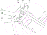
fig. 3 is a schematic structural view of the junction between the host connecting seat and the integrated cooker host of the present invention.
Detailed Description
The invention will be described in further detail with reference to the accompanying figures 1-3 and the detailed description, but they are not intended to limit the invention:
example 1
As shown in fig. 1, 2 and 3, the rice gas connecting structure of the integrated cooking range part and the host comprises an integrated cooking range part 1 and an integrated cooking range host 5, wherein the integrated cooking range part 1 is installed on the integrated cooking range host 5, and further comprises a head connecting seat 3, a host connecting seat 7, a head rice pipe 8, a head gas pipe 2, a host rice pipe 6 and a host gas pipe 4, the head connecting seat 3 is arranged at the lower end of the integrated cooking range part 1, the host connecting seat 7 is arranged on the integrated cooking range host 5, the head connecting seat 3 is matched with the host connecting seat 7, the head rice pipe 8 and the head gas pipe 2 are respectively connected with the head connecting seat 3, the host rice pipe 6 and the host gas pipe 4 are respectively connected with the host connecting seat 7, the head rice pipe 8 is communicated with the host rice pipe 6, and the head gas pipe 2 is communicated with the host gas pipe 4.
During the installation, install head connecting seat 3 on integrated kitchen range portion 1 earlier, then install host computer connecting seat 7 on integrated kitchen host computer 5, be connected head rice pipe 8, head trachea 2 and head connecting seat 3 respectively after that, be connected host computer rice pipe 6, host computer trachea 4 and host computer connecting seat 7 respectively, be connected host computer connecting seat 7 and head connecting seat 3 again and make integrated kitchen range portion 1 be connected with integrated kitchen range host computer 5, accomplish the utility model discloses an equipment.
Preferably, the main unit connecting base 7 is provided with a connecting base rice pipe convex column 72 and a connecting base air pipe convex column 71, the head connecting base 3 is provided with a connecting base rice pipe connecting hole 32 and a connecting base air pipe connecting hole 31, the connecting base rice pipe convex column 72 is in sealing connection with the connecting base rice pipe connecting hole 32, and the connecting base air pipe convex column 71 is in sealing connection with the connecting base air pipe connecting hole 31.
Preferably, the head connecting base 3 is further provided with two first sealing rings 9, the first sealing rings 9 seal the connecting base rice pipe convex column 72 and the joint of the head connecting base 3, and the first sealing rings 9 seal the connecting base rice pipe convex column 71 and the joint of the head connecting base 3
Preferably, the head connecting seat 3 is provided with a head rice tube connecting column 34 and a head air tube connecting column 33, the host connecting seat 7 is provided with a host rice tube connecting column 74 and a host air tube connecting column 73, the head rice tube connecting column 34 is in sealing connection with the head rice tube 8, the head air tube connecting column 33 is in sealing connection with the head air tube 2, the host rice tube connecting column 74 is in sealing connection with the host rice tube 6, and the host air tube connecting column 73 is in sealing connection with the host air tube 4.
Preferably, the device further comprises a head rice tube fastener 36, a head rice tube fastener 35, a host rice tube fastener 76 and a host air tube fastener 75, a head rice tube connecting column convex ring 341 is arranged at the joint of the head rice tube connecting column 34 and the head connecting seat 3, a head air tube connecting column convex ring 331 is arranged at the joint of the head air tube connecting column 33 and the head connecting seat 3, a host rice tube connecting column convex ring 741 is arranged at the joint of the host rice tube connecting column 74 and the host connecting seat 7, a host air tube connecting column convex ring 731 is arranged at the joint of the host air tube connecting column 73 and the host connecting seat 7, the head rice tube fastener 36 is matched with the head connecting seat 3 to clamp the head rice tube connecting column convex ring 341, and the head air tube fastener 35 is matched with the head connecting seat 3 to clamp the head air tube connecting column convex ring 331, the host machine rice pipe fastener 76 and the host machine connecting seat 7 are matched to clamp the host machine rice pipe connecting column convex ring 741, and the host machine trachea fastener 75 and the host machine connecting seat 7 are matched to clamp the host machine trachea connecting column convex ring 731.
Preferably, the air pipe connector further comprises four second sealing rings 10, the second sealing rings 10 are located at the joint of the host machine connecting seat 7 and the host machine air pipe connecting column convex ring 731, the second sealing rings 10 are located at the joint of the host machine connecting seat 7 and the host machine air pipe connecting column convex ring 741, the second sealing rings 10 seal the joint of the head connecting seat 3 and the head air pipe connecting column convex ring 331, and the second sealing rings 10 seal the joint of the head connecting seat 3 and the head air pipe connecting column convex ring 341.
Preferably, the head rice pipe fastener 36 is in threaded connection with the head connecting seat 3, the head air pipe fastener 35 is in threaded connection with the head connecting seat 3, the host rice pipe fastener 76 is in threaded connection with the host connecting seat 7, and the host air pipe fastener 75 is in threaded connection with the host connecting seat 7.
Preferably, the main unit connecting seat 7 is provided with a plug 79, the integrated cooker main unit 5 is provided with a slot 51, and the plug 79 is matched with the slot 51.
Preferably, a connecting plate 77 is arranged on one side of the main machine connecting seat 7, a main machine connecting seat threaded hole 78 is formed in the connecting plate 77, an integrated stove main machine threaded hole 52 is formed in the integrated stove main machine 5, and the main machine connecting seat threaded hole 78 corresponds to the integrated stove main machine threaded hole 52.
More specifically, install head connecting seat 3 on integrated kitchen range head 1 earlier, then insert bolt 79 slot 51 and correspond host computer connecting seat screw hole 78 and integrated kitchen host computer screw hole 52 and pass through the screw fixed, make host computer connecting seat 7 install on integrated kitchen host computer 5, then install head rice-sheeting tube fastener 36 screw thread on head connecting seat 3 and press from both sides head rice-sheeting tube connecting post bulge loop 341, install head trachea fastener 35 screw thread on head connecting seat 3 and press from both sides head trachea connecting post bulge loop 331, install host computer rice-sheeting tube fastener 76 screw thread on host computer connecting seat 7 and press from both sides host computer rice-sheeting tube connecting post bulge loop 741, install host computer trachea connecting post bulge loop 731 screw thread on host computer connecting seat 7 and press from both sides host computer trachea connecting post bulge loop 731. Then 8 covers head rice tube on head rice tube spliced pole 34, 2 covers head trachea on head rice tube spliced pole 33, 6 covers host computer rice tube on host computer rice tube spliced pole 74 with host computer trachea 4 covers on host computer trachea spliced pole 73, then with connecting seat rice tube projection 72 and connecting seat rice tube connecting hole 32 sealing connection, with connecting seat trachea projection 71 and connecting seat trachea connecting hole 31 sealing connection, accomplish host computer connecting seat 7 and be connected with head connecting seat 3, make integrated kitchen head 1 be connected with integrated kitchen host computer 5, accomplish the utility model discloses an equipment.
In short, the above description is only a preferred embodiment of the present invention, and all the equivalent changes and modifications made within the scope of the claims of the present invention should be covered by the present invention.
Claims (9)
1. Rice gas connection structure of integrated kitchen range portion and host computer, including integrated kitchen range portion (1) and integrated kitchen host computer (5), install on integrated kitchen host computer (5) integrated kitchen range portion (1), its characterized in that: still include head connecting seat (3), host computer connecting seat (7), head rice pipe (8), head trachea (2), host computer rice pipe (6), host computer trachea (4), head connecting seat (3) set up integrated kitchen range portion (1) lower extreme, host computer connecting seat (7) set up on integrated kitchen host computer (5), head connecting seat (3) with host computer connecting seat (7) cooperation, head rice pipe (8), head trachea (2) respectively with head connecting seat (3) are connected, host computer rice pipe (6), host computer trachea (4) respectively with host computer connecting seat (7) are connected, head rice pipe (8) with host computer rice pipe (6) intercommunication, head trachea (2) with host computer trachea (4) intercommunication.
2. The rice gas connecting structure of the integrated cooking range and the main machine according to claim 1, wherein: the main machine connecting seat (7) is provided with a connecting seat rice pipe convex column (72) and a connecting seat air pipe convex column (71), the head connecting seat (3) is provided with a connecting seat rice pipe connecting hole (32) and a connecting seat air pipe connecting hole (31), the connecting seat rice pipe convex column (72) is in sealing connection with the connecting seat rice pipe connecting hole (32), and the connecting seat air pipe convex column (71) is in sealing connection with the connecting seat air pipe connecting hole (31).
3. The rice gas connecting structure of the integrated cooking range and the main machine according to claim 2, wherein: the head connecting seat (3) is further provided with two first sealing rings (9), the first sealing rings (9) seal the connecting seat rice pipe convex column (72) and the connecting part of the head connecting seat (3), and the first sealing rings (9) seal the connecting seat rice pipe convex column (71) and the connecting part of the head connecting seat (3).
4. The rice gas connecting structure of the integrated cooking range and the main machine according to claim 1, wherein: head connecting seat (3) are provided with head rice tube connecting post (34), head trachea connecting post (33), host computer connecting seat (7) are provided with host computer rice tube connecting post (74), host computer trachea connecting post (73), head rice tube connecting post (34) with head rice tube (8) sealing connection, head trachea connecting post (33) with head trachea (2) sealing connection, host computer rice tube connecting post (74) with host computer rice tube (6) sealing connection, host computer trachea connecting post (73) with host computer trachea (4) sealing connection.
5. The rice gas connecting structure of the integrated cooking range and the main machine according to claim 4, wherein: the device also comprises a head rice-tube fastener (36), a head air-tube fastener (35), a host rice-tube fastener (76) and a host air-tube fastener (75), a head rice-tube connecting column convex ring (341) is arranged at the joint of the head rice-tube connecting column (34) and the head connecting seat (3), a head air-tube connecting column convex ring (331) is arranged at the joint of the head air-tube connecting column (33) and the head connecting seat (3), a host rice-tube connecting column convex ring (741) is arranged at the joint of the host rice-tube connecting column (74) and the host connecting seat (7), a host air-tube connecting column convex ring (731) is arranged at the joint of the host air-tube connecting column (73) and the host connecting seat (7), and the head rice-tube fastener (36) is matched with the head connecting seat (3) to clamp the head rice, head trachea fastener (35) with head connecting seat (3) cooperation is pressed from both sides head trachea spliced pole bulge loop (331), host computer rice pipe fastener (76) with host computer connecting seat (7) cooperation is pressed from both sides host computer rice pipe spliced pole bulge loop (741), host computer trachea fastener (75) with host computer connecting seat (7) cooperation is pressed from both sides host computer trachea spliced pole bulge loop (731).
6. The rice gas connecting structure of the integrated cooking range and the main machine according to claim 5, wherein: still include four second sealing washer (10), the junction of host computer connecting seat (7) and host computer trachea spliced pole bulge loop (731) is sealed in second sealing washer (10), second sealing washer (10) are located the junction of host computer connecting seat (7) and host computer meter tube spliced pole bulge loop (741), the junction of head connecting seat (3) and head trachea spliced pole bulge loop (331) is sealed in second sealing washer (10), the junction of head connecting seat (3) and head meter tube spliced pole bulge loop (341) is sealed in second sealing washer (10).
7. The rice gas connecting structure of the integrated cooking range and the main machine according to claim 5, wherein: the head meter pipe fastener (36) is in threaded connection with the head connecting seat (3), the head air pipe fastener (35) is in threaded connection with the head connecting seat (3), the host meter pipe fastener (76) is in threaded connection with the host connecting seat (7), and the host air pipe fastener (75) is in threaded connection with the host connecting seat (7).
8. The rice gas connecting structure of the integrated cooking range and the main machine according to claim 1, wherein: the integrated stove is characterized in that a plug pin (79) is arranged on the host machine connecting seat (7), a slot (51) is arranged on the integrated stove host machine (5), and the plug pin (79) is matched with the slot (51).
9. The rice gas connecting structure of the integrated cooking range and the main machine according to claim 1, wherein: the integrated stove is characterized in that a connecting plate (77) is arranged on one side of the host connecting seat (7), a host connecting seat threaded hole (78) is formed in the connecting plate (77), an integrated stove host threaded hole (52) is formed in the integrated stove host (5), and the host connecting seat threaded hole (78) corresponds to the integrated stove host threaded hole (52).
Priority Applications (1)
| Application Number | Priority Date | Filing Date | Title |
|---|---|---|---|
| CN202021629101.2U CN213309132U (en) | 2020-08-07 | 2020-08-07 | Rice gas connecting structure of integrated kitchen range head and main machine |
Applications Claiming Priority (1)
| Application Number | Priority Date | Filing Date | Title |
|---|---|---|---|
| CN202021629101.2U CN213309132U (en) | 2020-08-07 | 2020-08-07 | Rice gas connecting structure of integrated kitchen range head and main machine |
Publications (1)
| Publication Number | Publication Date |
|---|---|
| CN213309132U true CN213309132U (en) | 2021-06-01 |
Family
ID=76095621
Family Applications (1)
| Application Number | Title | Priority Date | Filing Date |
|---|---|---|---|
| CN202021629101.2U Active CN213309132U (en) | 2020-08-07 | 2020-08-07 | Rice gas connecting structure of integrated kitchen range head and main machine |
Country Status (1)
| Country | Link |
|---|---|
| CN (1) | CN213309132U (en) |
-
2020
- 2020-08-07 CN CN202021629101.2U patent/CN213309132U/en active Active
Similar Documents
| Publication | Publication Date | Title |
|---|---|---|
| CN208900375U (en) | A kind of easy-to-dismount electric emergency fire pump | |
| CN213309132U (en) | Rice gas connecting structure of integrated kitchen range head and main machine | |
| CN208356237U (en) | A kind of piping filter being convenient for changing filter core | |
| CN201284891Y (en) | Connection combination unit used for pump cover output connector and high-pressure pipe of high-pressure water pump | |
| CN217272673U (en) | Gas self-closing valve capable of being rapidly installed and detached | |
| CN205064158U (en) | Diesel engine is with horizontal cavate oil spout structure | |
| CN215806741U (en) | Trachea inserts structure soon | |
| CN202612930U (en) | A joint assembly and a pneumatic pipeline system having the same | |
| CN205991176U (en) | A kind of Medical gas terminal | |
| CN220134880U (en) | High-pressure union with reliable sealing | |
| CN201902743U (en) | Joint connecting device | |
| CN111928040A (en) | But quick assembly disassembly's valve pipe joint | |
| CN219082519U (en) | Pipeline flange connector | |
| CN214215758U (en) | Combined relay valve | |
| CN215635234U (en) | Connect pulse valve soon | |
| CN208268592U (en) | A kind of quartz connecting flange | |
| CN202266407U (en) | Convenient and rapid connected vector pump | |
| CN216692330U (en) | Pressure-stabilizing water path protection faucet | |
| CN218629320U (en) | High-efficient pressure testing device of formula heat exchange tube proclaims oneself | |
| CN218544644U (en) | Novel refrigerant pipe group for air conditioner | |
| CN203532261U (en) | Oil separating system of air compressor | |
| CN219388966U (en) | High-voltage connector special for aviation equipment | |
| CN219977495U (en) | Modular stainless steel water watchcase | |
| CN219866238U (en) | High-pressure multiple sealing structure and high-pressure cleaning machine | |
| CN211649389U (en) | Sealing structure of natural gas pipeline interface |
Legal Events
| Date | Code | Title | Description |
|---|---|---|---|
| GR01 | Patent grant | ||
| GR01 | Patent grant |