CN213266045U - Continuous integrated water purification equipment - Google Patents
Continuous integrated water purification equipment Download PDFInfo
- Publication number
- CN213266045U CN213266045U CN202021907777.3U CN202021907777U CN213266045U CN 213266045 U CN213266045 U CN 213266045U CN 202021907777 U CN202021907777 U CN 202021907777U CN 213266045 U CN213266045 U CN 213266045U
- Authority
- CN
- China
- Prior art keywords
- fixedly connected
- filter
- pipe
- tank body
- water
- Prior art date
- Legal status (The legal status is an assumption and is not a legal conclusion. Google has not performed a legal analysis and makes no representation as to the accuracy of the status listed.)
- Active
Links
Images


Abstract
The utility model discloses a continuous type integration water purification unit relates to the sewage purification field, exists certain limitation for solving current sewage purification installation, in the sewage that contains the large granule grit of processing, the grit blocks up the filtration mesh easily for the long-time problem of going on that lasts of purification operation can not be long-time. The inside of purifying tank body includes that first filtration storehouse, second filter storehouse, third filter storehouse, fixedly connected with inlet tube on the bottom surface of purifying tank body, the inside upper end in first filtration storehouse is arranged in to the play water end of inlet tube, first filtration storehouse and second filter are separated through the filter between the storehouse, the axis position department rotatory of filter installs the pivot, the one end fixedly connected with separation rotary drum of pivot, other end fixed connection is in the rotation axis one end of outside motor.
Description
Technical Field
The utility model relates to a sewage purification field specifically is a continuous type integration water purification unit.
Background
Along with the development of society, people produce more and more sewage, in order to guarantee that sewage can obtain timely processing, avoid appearing large-scale environmental pollution, consequently appeared numerous sewage purification device of kind in the market.
The existing sewage purification device has certain limitations, when sewage containing large-particle sand stones is treated, the sand stones easily block filter meshes, so that the purification operation can not be continuously carried out for a long time, and the device can be continuously carried out for a long time in order to avoid the meshes from being blocked; therefore, the market urgently needs to develop a continuous integrated water purifying device to help people solve the existing problems.
SUMMERY OF THE UTILITY MODEL
An object of the utility model is to provide a continuous type integration water purification unit to current sewage purification installation has certain limitation among the solution above-mentioned background art, and in the sewage that contains the large granule grit of processing, the grit blocks up the filtration mesh easily, makes the long-time problem of going on that lasts of purification operation.
In order to achieve the above object, the utility model provides a following technical scheme: the utility model provides a continuous type integration water purification unit, includes the purifying tank body, the inside of purifying tank body includes that first filtration storehouse, second filter storehouse, third filter storehouse, fixedly connected with inlet tube on the bottom surface of purifying tank body, the inside upper end in first filtration storehouse is arranged in to the play water end of inlet tube, first filtration storehouse and second filter through the filter partition between the storehouse, the axis position department of filter is rotatory to be installed the pivot, the one end fixedly connected with separation rotary drum of pivot, other end fixed connection are in the rotation axis one end of external motor, the separation rotary drum is located first inside upper end of filtering the storehouse, be provided with on the surface of filter and filter the through-hole, and the internally mounted who filters the through-hole has the filter screen.
Preferably, the outer surface of the upper end of the filter plate is fixedly connected with a mixing shell, the mixing shell is positioned inside the second filter bin, the side surface of the purification tank body is fixedly connected with a feeding hopper, and a discharge port of the feeding hopper is communicated with the inside of the second filter bin.
Preferably, be provided with the baffle between second filtration storehouse and the third filtration storehouse, and the axis position department fixedly connected with drinking-water pipe of baffle, the inside lower extreme of mixing the casing is arranged in to the end of intaking of drinking-water pipe, the pivot runs through in the inside of drinking-water pipe, and fixedly connected with helical blade on the surface of pivot, helical blade is located the inside of drinking-water pipe.
Preferably, the upper end of the side surface of the water pumping pipe is fixedly connected with a water guide pipe, the water outlet end of the water guide pipe is arranged in the separating cylinder, one end of the separating cylinder is in an open shape and is rotatably installed on the inner wall of the third filtering bin, the separating cylinder is in a net structure, the inner end surface of the separating cylinder is fixedly connected with a connecting seat, the middle position of the outer surface of one side of the connecting seat is fixedly connected with a connecting rod, one end of the connecting rod is fixedly connected with a fan blade, the fan blade is positioned in the water guide pipe, an active carbon filtering box is arranged below the separating cylinder, a drain pipe is fixedly connected on the side surface of the purifying tank body, the water inlet end of the drain pipe is communicated with the cavity below the active carbon filtering box, a high-pressure air pipe is fixedly installed on the outer surface of the upper end of the purifying, and the separation cylinder is arranged above the separation cylinder, a material guiding plate is obliquely arranged in the separation cylinder, and the discharge end of the material guiding plate is arranged outside the purification tank body.
Preferably, the side surface of the purification tank body is fixedly connected with a sand discharge pipe, and the sand discharge pipe is communicated with the bottom end in the first filter bin.
Preferably, the water inlet end of the water inlet pipe is connected with the water outlet end of the submersible pump through a hose.
Compared with the prior art, the beneficial effects of the utility model are that:
1. the utility model enables the interior of the purifying tank body to comprise a first filtering bin, a second filtering bin and a third filtering bin, the bottom outer surface of the purifying tank body is fixedly connected with a water inlet pipe, the water outlet end of the water inlet pipe is arranged at the inner upper end of the first filtering bin, the first filtering bin and the second filtering bin are separated by a filtering plate, the middle shaft of the filtering plate is rotatably provided with a rotating shaft, one end of the rotating shaft is fixedly connected with a separating rotating drum which is arranged at the inner upper end of the first filtering bin, the outer surface of the filtering plate is provided with filtering through holes, and the filtering through holes are internally provided with filtering screens, the device can be provided with three different filtering operations by utilizing different filtering mechanisms in the first filtering bin, the second filtering bin and the third filtering bin, the purifying effect of the whole device is effectively improved, and simultaneously, the separating rotating drum rotates in the first filtering bin, make the first inside sewage that filters the storehouse of entering take place the rotation, the grit of great granule is arranged in the first marginal position department that filters the storehouse in the sewage under the effect of centrifugal force this moment, and the sewage that does not contain large granule grit then passes the filter screen on the filter, and the inside that the storehouse was filtered to the entering second has also avoided the grit to block up when effectually having removed large granule grit and has filtered the mesh, has guaranteed that this purifier can last carry out filtering operation.
Drawings
FIG. 1 is an internal structural view of the present invention;
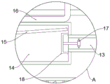
FIG. 2 is an enlarged view of the point A of the present invention;
fig. 3 is a top view of the filter plate of the present invention.
In the figure: 1. purifying the tank body; 2. a first filtration bin; 3. a water inlet pipe; 4. a submersible pump; 5. a separation drum; 6. a rotating shaft; 7. a filter plate; 8. a second filtration bin; 9. a mixing housing; 10. a water pumping pipe; 11. a helical blade; 12. a hopper; 13. a water conduit; 14. a separation cylinder; 15. a fuse plate; 16. a high-pressure air pipe; 17. a fan blade; 18. a connecting seat; 19. an activated carbon filter box; 20. a drain pipe; 21. and a third filtering bin.
Detailed Description
The technical solutions in the embodiments of the present invention will be described clearly and completely with reference to the accompanying drawings in the embodiments of the present invention, and it is obvious that the described embodiments are only some embodiments of the present invention, not all embodiments.
Referring to fig. 1-3, the present invention provides an embodiment: a continuous integrated water purifying device comprises a purifying tank body 1, wherein the purifying tank body 1 is internally provided with a first filtering bin 2, a second filtering bin 8 and a third filtering bin 21, a water inlet pipe 3 is fixedly connected to the outer surface of the bottom end of the purifying tank body 1, the water outlet end of the water inlet pipe 3 is arranged at the upper end of the inside of the first filtering bin 2, the first filtering bin 2 is separated from the second filtering bin 8 through a filtering plate 7, a rotating shaft 6 is rotatably arranged at the middle shaft position of the filtering plate 7, one end of the rotating shaft 6 is fixedly connected with a separation rotary drum 5, the other end of the rotating shaft is fixedly connected with one end of a rotating shaft of an external motor, the separation rotary drum 5 is arranged at the upper end of the inside of the first filtering bin 2, a filtering through hole is arranged on the outer surface of the filtering plate 7, a filtering screen is arranged in the filtering through hole, and the device can utilize different filtering mechanisms in the first filtering bin 2, effectual purifying effect who has improved whole device, simultaneously through separation rotary drum 5 in the first inside rotation of filter storehouse 2, make the first sewage of filtering 2 inside filter storehouses that gets into take place rotatoryly, the great grit of granule is arranged in the first border position department of filtering storehouse 2 under the effect of centrifugal force this moment in sewage, and the sewage that does not contain the large granule grit then passes the filter screen on the filter 7, get into the inside of second filter storehouse 8, also avoided the grit to block up when the effectual large granule grit of having rejected and filtered the mesh, the filtration operation that carries on that this purifier can last has been guaranteed.
Further, fixedly connected with mixes casing 9 on the upper end surface of filter 7, mixes casing 9 and is located the inside of second filter storehouse 8, and fixedly connected with loading hopper 12 on the side surface of the purification tank body 1, the discharge port of loading hopper 12 filters 8 inside communicating with each other with the second.
Further, a partition plate is arranged between the second filtering bin 8 and the third filtering bin 21, a water pumping pipe 10 is fixedly connected to the middle shaft of the partition plate, the water inlet end of the water pumping pipe 10 is arranged at the lower end of the inside of the mixing shell 9, the rotating shaft 6 penetrates through the inside of the water pumping pipe 10, a spiral blade 11 is fixedly connected to the outer surface of the rotating shaft 6, and the spiral blade 11 is located inside the water pumping pipe 10.
Further, the upper end of the side surface of the water pumping pipe 10 is fixedly connected with a water guide pipe 13, the water outlet end of the water guide pipe 13 is arranged inside a separating cylinder 14, one end of the separating cylinder 14 is in an open shape and is rotatably installed on the inner wall of a third filtering bin 21, the separating cylinder 14 is in a net structure, the inner end surface of the separating cylinder 14 is fixedly connected with a connecting seat 18, the middle position of the outer surface of one side of the connecting seat 18 is fixedly connected with a connecting rod, one end of the connecting rod is fixedly connected with a fan blade 17, the fan blade 17 is positioned inside the water guide pipe 13, an activated carbon filtering box 19 is arranged below the separating cylinder 14, a water discharge pipe 20 is fixedly connected with the side surface of the purifying tank body 1, the water inlet end of the water discharge pipe 20 is communicated with the cavity below the activated carbon filtering box 19, a high pressure air pipe 16 is fixedly installed on the outer surface of the upper end of, the separation cylinder 14 is internally provided with a material guiding plate 15 which is obliquely arranged, and the discharge end of the material guiding plate 15 is arranged outside the purification tank body 1.
Further, fixedly connected with sand discharge pipe on the side surface of the purification tank body 1, and the sand discharge pipe communicates with each other with the inside bottom of first filtration storehouse 2.
Furthermore, the water inlet end of the water inlet pipe 3 is connected with the water outlet end of the submersible pump 4 through a hose.
The working principle is as follows: when in use, the device is firstly installed at a specified position, then a power supply and an external compressed air source are switched on, then the submersible pump 4 is arranged in a sewage pool to be treated, the submersible pump 4 is started, at the moment, sewage passes through the water inlet pipe 3 to enter the first filtering bin 2, then the external motor is started, so that the rotating shaft 6 starts to rotate, the separation rotary drum 5 starts to rotate under the driving of the rotating shaft 6, at the moment, the separation rotary drum 5 enables the sewage in the first filtering bin 2 to rotate, then large-particle sand stones in the sewage are arranged at the edge position of the first filtering bin 2 under the action of centrifugal force, the sewage without the large-particle sand stones passes through the filter screen on the filter plate 7 to enter the second filtering bin 8, at the moment, a chemical agent is added into the sewage in the second filtering bin 8 through the feeding hopper 12, and as the quantity of the sewage is more and more, the sewage mixed with the chemical agent finally flows into the mixing shell, the rotation of the rotating shaft 6 drives the rotation of the helical blade 11, at this time, the pumping pipe 10 pumps the sewage at the bottom end inside the mixing shell 9 into the top end inside the pumping pipe 10, and guides the sewage into the inside of the water guide pipe 13, under the guidance of the water conduit 13, the sewage enters the interior of the separation cylinder 14, and when the sewage flows through the fan blades 17, so that the fan blades 17 rotate to drive the separating cylinder 14 to rotate, at the moment, the separating cylinder 14 filters flocculate in the sewage, and the flocculate rotates along with the rotation of the separating cylinder 14, when the flocs are transferred to the top of the inner point of the separation cylinder 14, the high-pressure gas pipe 16 is started, and the flocs fall on the guide plate 15 by the high-pressure gas sprayed from the high-pressure gas pipe 16 and are transferred to the outside of the purification tank 1, the sewage filtered by the separating drum 14 is filtered by the activated carbon in the activated carbon filtering box 19 and then discharged from the drain pipe 20.
It is obvious to a person skilled in the art that the invention is not restricted to details of the above-described exemplary embodiments, but that it can be implemented in other specific forms without departing from the spirit or essential characteristics of the invention. The present embodiments are therefore to be considered in all respects as illustrative and not restrictive, the scope of the invention being indicated by the appended claims rather than by the foregoing description, and all changes which come within the meaning and range of equivalency of the claims are therefore intended to be embraced therein. Any reference sign in a claim should not be construed as limiting the claim concerned.
Claims (6)
1. The utility model provides a continuous type integration water purification unit, includes purifying tank body (1), its characterized in that: the interior of the purifying tank body (1) comprises a first filtering bin (2), a second filtering bin (8) and a third filtering bin (21), a water inlet pipe (3) is fixedly connected on the outer surface of the bottom end of the purifying tank body (1), the water outlet end of the water inlet pipe (3) is arranged at the upper end of the interior of the first filtering bin (2), the first filtering bin (2) and the second filtering bin (8) are separated by a filtering plate (7), a rotating shaft (6) is rotatably arranged at the middle shaft position of the filter plate (7), one end of the rotating shaft (6) is fixedly connected with a separating rotating drum (5), the other end is fixedly connected with one end of a rotating shaft of an external motor, the separation rotary drum (5) is positioned at the upper end of the interior of the first filtering bin (2), the outer surface of the filter plate (7) is provided with a filter through hole, and a filter screen is arranged in the filter through hole.
2. The continuous integrated water purification device of claim 1, wherein: fixedly connected with mixes casing (9) on the upper end surface of filter (7), mix inside that casing (9) are located second filter storehouse (8), fixedly connected with loading hopper (12) on the side surface of purifying tank body (1), the discharge port of loading hopper (12) filters storehouse (8) with the second and communicates with each other inside.
3. The continuous integrated water purification device of claim 2, wherein: be provided with the baffle between second filtration storehouse (8) and third filtration storehouse (21), and the axis position department fixedly connected with drinking-water pipe (10) of baffle, the inside lower extreme of mixing casing (9) is arranged in to the end of intaking of drinking-water pipe (10), pivot (6) run through in the inside of drinking-water pipe (10), and fixedly connected with helical blade (11) on the surface of pivot (6), helical blade (11) are located the inside of drinking-water pipe (10).
4. The continuous integrated water purification device of claim 3, wherein: the utility model discloses a water purification tank, including drinking-water pipe (10), separator (14), connecting seat (18) and connecting rod, the intermediate position department fixedly connected with connecting rod of connecting seat (18) one side surface, and the one end fixedly connected with flabellum (17) of connecting rod, flabellum (17) are located the inside of aqueduct (13), the below of separator (14) is provided with active carbon filter box (19), fixedly connected with drain pipe (20) on the side surface of the purification tank body (1), the end of intaking of drain pipe (20) communicates with each other with the below cavity of active carbon filter box (19), the outer surface of the upper end of the purification tank body (1) is fixedly provided with a high-pressure air pipe (16), the high-pressure air pipe (16) is arranged in the third filter bin (21) and is positioned above the separation cylinder (14), the separation cylinder (14) is internally provided with a material guiding plate (15) which is obliquely arranged, and the discharge end of the material guiding plate (15) is arranged outside the purification tank body (1).
5. The continuous integrated water purification device of claim 1, wherein: the sand discharge pipe is fixedly connected to the side surface of the purifying tank body (1), and the sand discharge pipe is communicated with the bottom end of the first filtering bin (2).
6. The continuous integrated water purification device of claim 1, wherein: the water inlet end of the water inlet pipe (3) is connected with the water outlet end of the submersible pump (4) through a hose.
Priority Applications (1)
| Application Number | Priority Date | Filing Date | Title |
|---|---|---|---|
| CN202021907777.3U CN213266045U (en) | 2020-09-04 | 2020-09-04 | Continuous integrated water purification equipment |
Applications Claiming Priority (1)
| Application Number | Priority Date | Filing Date | Title |
|---|---|---|---|
| CN202021907777.3U CN213266045U (en) | 2020-09-04 | 2020-09-04 | Continuous integrated water purification equipment |
Publications (1)
| Publication Number | Publication Date |
|---|---|
| CN213266045U true CN213266045U (en) | 2021-05-25 |
Family
ID=75937783
Family Applications (1)
| Application Number | Title | Priority Date | Filing Date |
|---|---|---|---|
| CN202021907777.3U Active CN213266045U (en) | 2020-09-04 | 2020-09-04 | Continuous integrated water purification equipment |
Country Status (1)
| Country | Link |
|---|---|
| CN (1) | CN213266045U (en) |
Cited By (1)
| Publication number | Priority date | Publication date | Assignee | Title |
|---|---|---|---|---|
| CN115430193A (en) * | 2022-09-02 | 2022-12-06 | 江苏昂跨环保科技有限公司 | Multifunctional water purifier |
-
2020
- 2020-09-04 CN CN202021907777.3U patent/CN213266045U/en active Active
Cited By (1)
| Publication number | Priority date | Publication date | Assignee | Title |
|---|---|---|---|---|
| CN115430193A (en) * | 2022-09-02 | 2022-12-06 | 江苏昂跨环保科技有限公司 | Multifunctional water purifier |
Similar Documents
| Publication | Publication Date | Title |
|---|---|---|
| CN211311149U (en) | Multifunctional integrated sewage treatment equipment | |
| CN112253472A (en) | Automatic control drainage system of centrifugal pump | |
| CN208949033U (en) | A kind of recirculated water automatic dosing apparatus with filtering function | |
| CN213266045U (en) | Continuous integrated water purification equipment | |
| CN110759518A (en) | Urban sewage comprehensive treatment device | |
| CN211724858U (en) | Sewage filtering device and domestic sewage treatment device | |
| CN116395909A (en) | Chip cutting waste water filter equipment | |
| CN215088668U (en) | Sand and stone separating device for processing recycled concrete | |
| CN214270523U (en) | Advanced treatment equipment for coal chemical industry process wastewater | |
| CN214880639U (en) | Multistage sewage treatment device | |
| US20210129073A1 (en) | Deodorizing device and intelligent toilet | |
| CN211487629U (en) | Microwave hydrolysis device | |
| CN211847598U (en) | Integrated buried sewage purification equipment | |
| CN211111506U (en) | Box integration groundwater pollution normal position prosthetic devices | |
| CN210079101U (en) | Environment-friendly dust exhaust treatment device | |
| CN113087224A (en) | Environment-friendly equipment for chemical wastewater purification and purification method thereof | |
| CN111675458A (en) | River sludge treatment device for ecological environment protection | |
| CN111517501A (en) | Sewage treatment device convenient to overhaul | |
| CN216404067U (en) | Groundwater pollution treatment device | |
| CN215049426U (en) | A sewage treatment plant for industrial park | |
| CN212924907U (en) | Oil peculiar smell clearing device | |
| CN213037538U (en) | Bury prefabricated formula poultry sewage purification unit | |
| CN219409319U (en) | Swift cluster cylinder water purification device | |
| CN210506007U (en) | Environment-friendly dewatering equipment for sludge treatment | |
| CN220502731U (en) | Screening and filtering device for recycling noble metals in waste |
Legal Events
| Date | Code | Title | Description |
|---|---|---|---|
| GR01 | Patent grant | ||
| GR01 | Patent grant |