CN213243103U - Angle-adjustable laser - Google Patents
Angle-adjustable laser Download PDFInfo
- Publication number
- CN213243103U CN213243103U CN202022290281.2U CN202022290281U CN213243103U CN 213243103 U CN213243103 U CN 213243103U CN 202022290281 U CN202022290281 U CN 202022290281U CN 213243103 U CN213243103 U CN 213243103U
- Authority
- CN
- China
- Prior art keywords
- fixedly connected
- box
- laser instrument
- carousel
- laser
- Prior art date
- Legal status (The legal status is an assumption and is not a legal conclusion. Google has not performed a legal analysis and makes no representation as to the accuracy of the status listed.)
- Active
Links
Images
Abstract
The utility model discloses an angle-adjustable's laser instrument, including laser instrument body and box, the bottom fixedly connected with motor of box inner chamber, the output fixedly connected with bull stick of motor, the top of bull stick runs through to the top and the fixedly connected with carousel of box, the left side fixedly connected with riser at carousel top, the right side fixedly connected with hydraulic telescoping rod at carousel top, hydraulic telescoping rod's top and the bottom fixed connection of laser instrument body, the bottom fixedly connected with mounting panel of box. The utility model discloses a cooperation of laser instrument body, box, motor, bull stick, carousel, riser and hydraulic telescoping rod is used, can make the laser instrument body can carry out the regulation of angle and direction according to the use needs, and the use of giving people has brought conveniently, has solved current laser instrument and can not be as required automatically regulated use angle, and the use of giving people has brought inconvenient problem.
Description
Technical Field
The utility model relates to a laser instrument technical field specifically is an angle-adjustable's laser instrument.
Background
The laser can send the laser device, the kind of laser device is divided according to working medium, the laser device can be divided into 4 kinds of gas laser device, solid laser device, semiconductor laser device and dyestuff laser device, free electron laser device has still been developed recently, high-power laser device all is pulsed output usually, but current laser device can not be as required automatically regulated use angle, has brought the inconvenience for people's use.
SUMMERY OF THE UTILITY MODEL
An object of the utility model is to provide an angle-adjustable's laser instrument possesses the advantage that can automatically regulated angle, has solved current laser instrument and can not use the angle as required automatically regulated, and the use of giving people has brought inconvenient problem.
In order to achieve the above object, the utility model provides a following technical scheme: the utility model provides an angle-adjustable's laser instrument, includes laser instrument body and box, the bottom fixedly connected with motor of box inner chamber, the output fixedly connected with bull stick of motor, the top of bull stick runs through to the top and the fixedly connected with carousel of box, the left side fixedly connected with riser at carousel top, the right side fixedly connected with hydraulic telescoping rod at carousel top, hydraulic telescoping rod's top and the bottom fixed connection of laser instrument body.
Preferably, the bottom fixedly connected with mounting panel of box, the mounting hole has all been seted up to the both sides of mounting panel.
Preferably, the bottom of the motor is fixedly connected with a fixed block, and the bottom of the fixed block is fixedly connected with the inner cavity of the box body.
Preferably, a circular sliding groove is formed in the top of the box body, pulleys are fixedly connected to the two sides of the bottom of the rotary table, and one side, away from the rotary table, of each pulley extends to the inner cavity of the circular sliding groove and is movably connected with the circular sliding groove.
Preferably, the right side of the vertical plate is fixedly connected with a toothed plate, the left end of the laser body is fixedly connected with a gear, and the gear is meshed with the toothed plate.
Compared with the prior art, the beneficial effects of the utility model are as follows:
1. the utility model discloses a cooperation of laser instrument body, box, motor, bull stick, carousel, riser and hydraulic telescoping rod is used, can make the laser instrument body can carry out the regulation of angle and direction according to the use needs, and the use of giving people has brought conveniently, has solved current laser instrument and can not be as required automatically regulated use angle, and the use of giving people has brought inconvenient problem.
2. The utility model discloses a set up mounting panel and mounting hole, can install better on other service equipment, through setting up the fixed block, can be with the better fixing of motor in the box, through setting up circular spout and pulley, can make the better rotation of carousel, through setting up pinion rack and gear, can make the better upper and lower angle regulation of laser instrument body.
Drawings
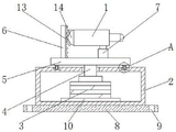
FIG. 1 is a schematic view of the internal structure of the present invention;
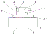
FIG. 2 is a schematic view of the external structure of the present invention;
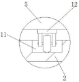
fig. 3 is a partially enlarged view of a portion a in fig. 1 according to the present invention.
In the figure: 1. a laser body; 2. a box body; 3. a motor; 4. a rotating rod; 5. a turntable; 6. a vertical plate; 7. a hydraulic telescopic rod; 8. mounting a plate; 9. mounting holes; 10. a fixed block; 11. a circular chute; 12. a pulley; 13. a toothed plate; 14. a gear.
Detailed Description
The technical solutions in the embodiments of the present invention will be described clearly and completely with reference to the accompanying drawings in the embodiments of the present invention, and it is obvious that the described embodiments are only some embodiments of the present invention, not all embodiments. Based on the embodiments in the present invention, all other embodiments obtained by a person skilled in the art without creative work belong to the protection scope of the present invention.
The components of the present invention are all standard components or components known to those skilled in the art, and the structure and principle thereof can be known by the technical manual or by the conventional experimental method.
Referring to fig. 1-3, an angle-adjustable laser includes a laser body 1 and a case 2, a mounting plate 8 is fixedly connected to the bottom of the case 2, mounting holes 9 are respectively formed on both sides of the mounting plate 8, the device can be better mounted on other devices, a circular chute 11 is formed in the top of the case 2, pulleys 12 are fixedly connected to both sides of the bottom of the turntable 5, one side of each pulley 12 away from the turntable 5 extends into an inner cavity of the circular chute 11 and is movably connected to the circular chute 11, the turntable 5 can better rotate by the arrangement of the circular chute 11 and the pulleys 12, a motor 3 is fixedly connected to the bottom of the inner cavity of the case 2, a fixing block 10 is fixedly connected to the bottom of the motor 3, the bottom of the fixing block 10 is fixedly connected to the inner cavity of the case 2, and by the arrangement of the fixing block 10, the motor 3 can be better fixed in the case 2, the output end of the motor 3 is fixedly connected with a rotating rod 4, the top of the rotating rod 4 penetrates through the top of the box body 2 and is fixedly connected with a rotary table 5, the left side of the top of the rotary table 5 is fixedly connected with a vertical plate 6, the right side of the vertical plate 6 is fixedly connected with a toothed plate 13, the left end of the laser body 1 is fixedly connected with a gear 14, the gear 14 is meshed with the toothed plate 13, the upper and lower adjusting angles of the laser body 1 can be better adjusted by arranging the toothed plate 13 and the gear 14, the right side of the top of the rotary table 5 is fixedly connected with a hydraulic telescopic rod 7, the top of the hydraulic telescopic rod 7 is fixedly connected with the bottom of the laser body 1, the box body 2, the motor 3, the rotating rod 4, the rotary table 5, the vertical plate 6 and the hydraulic telescopic rod 7 are matched for use, the angle and direction of the, the problem of current laser instrument can not as required automatically regulated use angle, the use of giving people has brought inconvenience is solved.
During the use, when the direction of shining of needs adjustment laser instrument body 1, starter motor 3, motor 3's output drives bull stick 4 and rotates, bull stick 4 drives carousel 5 and rotates, carousel 5 drives laser instrument body 1 and rotates, stop motor 3 after adjusting appointed irradiation angle, when the upper and lower irradiation angle that needs adjustment laser instrument body 1, start hydraulic telescoping rod 7, hydraulic telescoping rod 7 drives the right-hand member of laser instrument body 1 and upwards perhaps moves down, can reach the purpose of adjusting irradiation angle.
Although embodiments of the present invention have been shown and described, it will be appreciated by those skilled in the art that changes, modifications, substitutions and alterations can be made in these embodiments without departing from the principles and spirit of the invention, the scope of which is defined in the appended claims and their equivalents.
Claims (5)
1. The utility model provides an angle-adjustable's laser instrument, includes laser instrument body (1) and box (2), its characterized in that: the utility model discloses a laser instrument, including box (2), the bottom fixedly connected with motor (3) of box (2) inner chamber, the output end fixedly connected with bull stick (4) of motor (3), the top of bull stick (4) runs through top and fixedly connected with carousel (5) to box (2), the left side fixedly connected with riser (6) at carousel (5) top, the right side fixedly connected with hydraulic telescoping rod (7) at carousel (5) top, the top of hydraulic telescoping rod (7) and the bottom fixed connection of laser instrument body (1).
2. An adjustable angle laser as defined in claim 1, wherein: the bottom fixedly connected with mounting panel (8) of box (2), mounting hole (9) have all been seted up to the both sides of mounting panel (8).
3. An adjustable angle laser as defined in claim 1, wherein: the bottom fixedly connected with fixed block (10) of motor (3), the bottom of fixed block (10) and the inner chamber fixed connection of box (2).
4. An adjustable angle laser as defined in claim 1, wherein: circular spout (11) have been seted up at the top of box (2), the equal fixedly connected with pulley (12) in both sides of carousel (5) bottom, one side that carousel (5) were kept away from in pulley (12) extends to the inner chamber of circular spout (11) and with circular spout (11) swing joint.
5. An adjustable angle laser as defined in claim 1, wherein: the right side fixedly connected with pinion rack (13) of riser (6), the left end fixedly connected with gear (14) of laser body (1), gear (14) and pinion rack (13) meshing.
Priority Applications (1)
| Application Number | Priority Date | Filing Date | Title |
|---|---|---|---|
| CN202022290281.2U CN213243103U (en) | 2020-10-15 | 2020-10-15 | Angle-adjustable laser |
Applications Claiming Priority (1)
| Application Number | Priority Date | Filing Date | Title |
|---|---|---|---|
| CN202022290281.2U CN213243103U (en) | 2020-10-15 | 2020-10-15 | Angle-adjustable laser |
Publications (1)
| Publication Number | Publication Date |
|---|---|
| CN213243103U true CN213243103U (en) | 2021-05-18 |
Family
ID=75880781
Family Applications (1)
| Application Number | Title | Priority Date | Filing Date |
|---|---|---|---|
| CN202022290281.2U Active CN213243103U (en) | 2020-10-15 | 2020-10-15 | Angle-adjustable laser |
Country Status (1)
| Country | Link |
|---|---|
| CN (1) | CN213243103U (en) |
-
2020
- 2020-10-15 CN CN202022290281.2U patent/CN213243103U/en active Active
Similar Documents
| Publication | Publication Date | Title |
|---|---|---|
| CN211312765U (en) | Pipeline construction auxiliary fixtures | |
| CN109336019B (en) | Electric power overhauls device | |
| CN213243103U (en) | Angle-adjustable laser | |
| CN211395439U (en) | Multifunctional bridge construction warning device | |
| CN210413582U (en) | Anchor clamps are used in five metals automated processing | |
| CN112621848A (en) | Cutting device is used in aluminium alloy plastic-steel door and window manufacturing production | |
| CN217492751U (en) | Metal processing device with clamping mechanism | |
| CN215798342U (en) | Electrical safety elevator | |
| CN213765768U (en) | Multifunctional tool table for building electrical design | |
| CN216328154U (en) | Five metals electrical apparatus production is with assembly bench that has multi-angle to adjust structure | |
| CN220973475U (en) | Knurling device of degradable paper cup processing equipment | |
| CN207077030U (en) | A kind of open anchor head saw cut processing unit (plant) | |
| CN214186075U (en) | A high-efficient frock clamp for drilling tapping | |
| CN213401846U (en) | Laser with high working stability | |
| CN211541031U (en) | Side-mounted automatic tightening device | |
| CN214579947U (en) | Network monitoring device for property management | |
| CN220372081U (en) | Steel wire bending device for steel wire wheel | |
| CN218781041U (en) | Urban rail transit operation passenger flow monitoring facilities | |
| CN219129064U (en) | Ultrasonic stirrer | |
| CN220416813U (en) | Hidden face recognition device | |
| CN214335218U (en) | Distance measuring device for architectural design | |
| CN217452548U (en) | Spot welding machine convenient to height-adjusting | |
| CN216029369U (en) | Tool for milling gear box | |
| CN213765721U (en) | Operation panel convenient to adjust | |
| CN220259921U (en) | Welding set with protective structure |
Legal Events
| Date | Code | Title | Description |
|---|---|---|---|
| GR01 | Patent grant | ||
| GR01 | Patent grant |