CN213242937U - Connector and connector assembly - Google Patents
Connector and connector assembly Download PDFInfo
- Publication number
- CN213242937U CN213242937U CN202022120430.0U CN202022120430U CN213242937U CN 213242937 U CN213242937 U CN 213242937U CN 202022120430 U CN202022120430 U CN 202022120430U CN 213242937 U CN213242937 U CN 213242937U
- Authority
- CN
- China
- Prior art keywords
- connector
- sealing
- plug
- contact
- insulator
- Prior art date
- Legal status (The legal status is an assumption and is not a legal conclusion. Google has not performed a legal analysis and makes no representation as to the accuracy of the status listed.)
- Active
Links
Images


Abstract
The utility model relates to a connector for realize the break-make of circuit, provide a connector and connector assembly. The connector includes: a housing having an inner bore for receiving the ferrule member; the ferrule component is positioned and arranged in an inner hole of the shell along the front-back direction, and the front-back direction is the plugging direction of the connector; the ferrule member includes: an insulator positioned radially within the housing for supporting the contact; the contact piece is embedded in the insulator and used for realizing circuit conduction; the ferrule component comprises a sealing colloid which is provided with a sealing matching hole and a sealing peripheral surface; the sealing fit hole is used for the contact part to pass through and to be in sealing fit with the peripheral surface of the contact part; the sealing peripheral surface is used for being in sealing fit with the inner hole wall of the shell; the sealing colloid and the insulator are arranged in front and at the back, or the sealing colloid is formed by the insulator. Above-mentioned scheme has solved the difficult problem of guaranteeing of current connector sealing performance.
Description
Technical Field
The utility model relates to a connector for realize the break-make of circuit.
Background
Connectors are used in a wide variety of applications, often in the form of connector assemblies that include a plug connector and a receptacle connector that mate together in use. The plug connector and the socket connector are connected in a plugging mode comprising threaded connection, bayonet connection and locking ball connection. The threaded connection is that one of the plug connector and the socket connector is provided with an external thread, and the other one is provided with an internal thread; the bayonet connection is that a spiral groove is arranged on the plug connector or the socket connector, and a locking nail is arranged on the other plug connector or the socket connector and is locked through the spiral groove; the lock ball is connected to a connector disclosed in patent document No. CN 102820587A.
Plug and receptacle connectors sometimes require high sealing requirements. For example, with the development of 5G communication technology, the requirement for the reliability of the sealing protection level of the interface of the communication equipment is higher and higher, and the following requirements are generally required: 1. the fixed end connector (socket connector) of the equipment needs to realize open air sealing, namely liquid can not enter the equipment from the interface when the headstock (the plug connector and the socket connector) is in a non-plugging state, and whether the socket can meet the requirement or not is judged through air sealing test. Even, the following requirements may be present: 2. the free end connector (plug connector) also needs to meet the requirement of open air sealing, so that the possibility that liquid enters the plugging end face of the connector from the damaged part of the cable sheath can be avoided; in addition, when the plug is not in the plugging state, the plugging surface is accidentally met with water, and water cannot penetrate into the tail of the plug, so that the water is conveniently and quickly drained, and the redundancy of the protection capability is further improved.
However, if the plug connector adopts a conventional non-open sealing structure, the possibility that liquid enters the plug base plugging interface from the damaged cable or even enters the inside of the device cannot be avoided, the possibility that liquid enters the plug from the plug plugging surface or even enters the inside of the cable cannot be prevented, and the sealing performance is difficult to meet some specific requirements.
In addition, both threaded and bayonet connections require the operator to manually rotate the locking/unlocking feature, which requires sufficient space around the locking/unlocking feature to accommodate finger movement. To ensure a reliable connection, the locking and unlocking torque is usually high, sometimes requiring the operator even to wear anti-slip gloves or use a wrench. The operative space between the connectors is therefore usually much greater than the finger thickness for the operator to operate. Therefore, the installation density between the interfaces of the adjacent connectors is difficult to be improved, and the overall miniaturization design of the communication equipment is influenced. Moreover, since the coefficient of friction of the connector surface is generally small, an operator needs to additionally apply a large force to ensure slip prevention even when wearing slip-resistant gloves, and the experience of handling is generally poor. Especially threaded connection closes the number of turns soon more, has reduced the efficiency that the operator inserted the connector, and the convenience is relatively poor. For threaded connection, the arrangement of a thread anti-loosening measure is also required to be considered, and the connector is provided with an anti-loosening mechanism, and the connector is inserted into a heat-shrinkable tube which is sleeved in place, so that the miniaturization of the size of the connector and the convenience of operation are affected. The existing equipment miniaturization trend and equipment interface densification trend are prominent, the operation space for inserting and combining the head seat is smaller and smaller, the operation difficulty is improved, the possibility that an operator cannot insert and combine in place or misjudge the inserting and combining in place is increased, and therefore sealing failure of the interface is easily caused.
SUMMERY OF THE UTILITY MODEL
The utility model aims at providing a connector solves the difficult problem of guaranteeing of current connector sealing performance, simultaneously, another purpose of the utility model is to provide a connector assembly, solves the difficult problem that leads to whole leakproofness poor, the reliability poor of guaranteeing of current plug connector or socket connector's sealing performance.
The utility model discloses well connector adopts following technical scheme:
a connector, comprising:
a housing having an inner bore for receiving the ferrule member;
the ferrule component is positioned and arranged in an inner hole of the shell along the front-back direction, and the front-back direction is the plugging direction of the connector; the ferrule member includes:
an insulator positioned radially within the housing for supporting the contact;
the contact piece is embedded in the insulator and used for realizing circuit conduction;
the ferrule component comprises a sealing colloid which is provided with a sealing matching hole and a sealing peripheral surface;
the sealing fit hole is used for the contact part to pass through and to be in sealing fit with the peripheral surface of the contact part;
the sealing peripheral surface is used for being in sealing fit with the inner hole wall of the shell;
the sealing colloid and the insulator are arranged in front and at the back, or the sealing colloid is formed by the insulator.
Has the advantages that: adopt above-mentioned technical scheme, through the sealed mating holes and the sealed outer peripheral face of sealed colloid, the axial both sides of plug side sealed colloid can be isolated by sealed colloid to reach waterproof purpose, compare with prior art, can improve the sealing performance of connector, reduce the requirement to uncovered sealing performance, can adopt non-uncovered sealed, need not supporting waterproof sealing lid, be favorable to reduce cost.
As a preferred technical scheme: and the hole wall of the sealing matching hole and/or the outer peripheral surface of the seal are/is provided with annular bulges, and the annular bulges extend along the circumferential direction.
Has the advantages that: by adopting the technical scheme, the annular bulge is arranged, so that a better sealing effect can be achieved.
As a preferred technical scheme: more than two annular bulges are arranged on the hole wall of the sealing matching hole, and/or more than two annular bulges are arranged on the outer peripheral surface of the seal.
Has the advantages that: by adopting the technical scheme, the sealing performance is further improved.
As a preferred technical scheme: and one end of the shell in the front-back direction of the ferrule component is positioned through the stopping step, and the other end of the shell in the front-back direction of the ferrule component is positioned through a clamp spring arranged in the clamp spring groove.
Has the advantages that: by adopting the technical scheme, the positioning of the core inserting part can be conveniently realized, the structure is simple, and the technology is mature.
As a preferred technical scheme: the core insert component comprises a righting body, and the righting body is righted in an inner hole of the shell and is positioned at the rear end of the core insert component; the centralizing body is internally provided with a contact element positioning hole for centralizing the contact element along the radial direction.
Has the advantages that: by adopting the technical scheme, the centralizing body is arranged, so that the sealing colloid and the contact element can be well fixed, the contact element can be centered along the radial direction, and the sealing colloid caused by the deflection of the tail end of the contact element under the stress is prevented from losing efficacy.
As a preferred technical scheme: the centralizing body and the insulator are arranged at intervals in the front and back, and the sealing colloid is arranged between the insulator and the centralizing body.
Has the advantages that: by adopting the technical scheme, the sealing performance can be prevented from being influenced by the fact that the sealing colloid directly forms a stop with the shell.
As a preferred technical scheme: the sealing colloid is a sealing rubber gasket assembled between the insulator and the righting body, or is glue solution solidified between the insulator, the righting body and the shell.
Has the advantages that: by adopting the technical scheme, the sealing rubber mat is simple in structure, the contact of the solidified glue solution is more sufficient, and the sealing performance is good.
As a preferred technical scheme: the connector is provided with a plug hole, a plug sealing ring is arranged in the plug hole, the plug sealing ring is provided with a step sealing surface, and the step sealing surface comprises an axial sealing surface and a radial sealing surface which are respectively in sealing fit with the end face and the outer peripheral face of the plug end of the adaptive connector.
Has the advantages that: by adopting the technical scheme, the interface sealing performance during insertion can be further improved.
As a preferred technical scheme: the connector is provided with two contact elements, the diameter of the matching part of each contact element and the sealing colloid is 1.6 +/-0.2 mm, 3.15 +/-0.2 mm or 4.5 +/-0.2 mm, and the center distance of the two contact elements is 5.6 +/-0.5 mm, 8.1 +/-0.5 mm or 12 +/-0.5 mm in one-to-one correspondence;
or: the connector is provided with three contact elements, the three contact elements are parallel to each other, the central lines of the three contact elements are arranged in an equilateral triangle, the diameter of the matching part of each contact element and the sealing colloid is 1.6 +/-0.2 mm or 2.4 +/-0.2 mm, and the center distance between any two contact elements is 5.2 +/-0.5 mm and 6.4 +/-0.5 mm in one-to-one correspondence.
Has the advantages that: by adopting the technical scheme, the diameter of the plug contact element and the center distance of the contact element are adopted, the connector is embodied under the requirement of corresponding common working current indexes, the range of the adapting wire diameter can be maximized, the outline dimension can be minimized, and the sealing performance is most stable.
The utility model discloses well connector assembly adopts following technical scheme:
a connector assembly including a plug connector and a receptacle connector; the plug connector and/or the socket connector are the following connectors:
a connector, comprising:
a housing having an inner bore for receiving the ferrule member;
the ferrule component is positioned and arranged in an inner hole of the shell along the front-back direction, and the front-back direction is the plugging direction of the connector; the ferrule member includes:
an insulator positioned radially within the housing for supporting the contact;
the contact piece is embedded in the insulator and used for realizing circuit conduction;
the ferrule component comprises a sealing colloid which is provided with a sealing matching hole and a sealing peripheral surface;
the sealing fit hole is used for the contact part to pass through and to be in sealing fit with the peripheral surface of the contact part;
the sealing peripheral surface is used for being in sealing fit with the inner hole wall of the shell;
the sealing colloid and the insulator are arranged in front and at the back, or the sealing colloid is formed by the insulator.
Has the advantages that: adopt above-mentioned technical scheme, through the sealed mating holes and the sealed outer peripheral face of sealed colloid, the axial both sides of plug side sealed colloid can be isolated by sealed colloid to reach waterproof purpose, compare with prior art, can improve the sealing performance of connector, reduce the requirement to uncovered sealing performance, can adopt non-uncovered sealed, need not supporting waterproof sealing lid, be favorable to reduce cost, whole leakproofness is good, good reliability.
As a preferred technical scheme: and the hole wall of the sealing matching hole and/or the outer peripheral surface of the seal are/is provided with annular bulges, and the annular bulges extend along the circumferential direction.
Has the advantages that: by adopting the technical scheme, the annular bulge is arranged, so that a better sealing effect can be achieved.
As a preferred technical scheme: more than two annular bulges are arranged on the hole wall of the sealing matching hole, and/or more than two annular bulges are arranged on the outer peripheral surface of the seal.
Has the advantages that: by adopting the technical scheme, the sealing performance is further improved.
As a preferred technical scheme: and one end of the shell in the front-back direction of the ferrule component is positioned through the stopping step, and the other end of the shell in the front-back direction of the ferrule component is positioned through a clamp spring arranged in the clamp spring groove.
Has the advantages that: by adopting the technical scheme, the positioning of the core inserting part can be conveniently realized, the structure is simple, and the technology is mature.
As a preferred technical scheme: the core insert component comprises a righting body, and the righting body is righted in an inner hole of the shell and is positioned at the rear end of the core insert component; the centralizing body is internally provided with a contact element positioning hole for centralizing the contact element along the radial direction.
Has the advantages that: by adopting the technical scheme, the centralizing body is arranged, so that the sealing colloid and the contact element can be well fixed, the contact element can be centered along the radial direction, and the sealing colloid caused by the deflection of the tail end of the contact element under the stress is prevented from losing efficacy.
As a preferred technical scheme: the centralizing body and the insulator are arranged at intervals in the front and back, and the sealing colloid is arranged between the insulator and the centralizing body.
Has the advantages that: by adopting the technical scheme, the sealing performance can be prevented from being influenced by the fact that the sealing colloid directly forms a stop with the shell.
As a preferred technical scheme: the sealing colloid is a sealing rubber gasket assembled between the insulator and the righting body, or is glue solution solidified between the insulator, the righting body and the shell.
Has the advantages that: by adopting the technical scheme, the sealing rubber mat is simple in structure, the contact of the solidified glue solution is more sufficient, and the sealing performance is good.
As a preferred technical scheme: the connector is provided with a plug hole, a plug sealing ring is arranged in the plug hole, the plug sealing ring is provided with a step sealing surface, and the step sealing surface comprises an axial sealing surface and a radial sealing surface which are respectively in sealing fit with the end face and the outer peripheral face of the plug end of the adaptive connector.
Has the advantages that: by adopting the technical scheme, the interface sealing performance during insertion can be further improved.
As a preferred technical scheme: the connector is provided with two contact elements, the diameter of the matching part of each contact element and the sealing colloid is 1.6 +/-0.2 mm, 3.15 +/-0.2 mm or 4.5 +/-0.2 mm, and the center distance of the two contact elements is 5.6 +/-0.5 mm, 8.1 +/-0.5 mm or 12 +/-0.5 mm in one-to-one correspondence;
or: the connector is provided with three contact elements, the three contact elements are parallel to each other, the central lines of the three contact elements are arranged in an equilateral triangle, the diameter of the matching part of each contact element and the sealing colloid is 1.6 +/-0.2 mm or 2.4 +/-0.2 mm, and the center distance between any two contact elements is 5.2 +/-0.5 mm and 6.4 +/-0.5 mm in one-to-one correspondence.
Has the advantages that: by adopting the technical scheme, the diameter of the plug contact element and the center distance of the contact element are adopted, the connector is embodied under the requirement of corresponding common working current indexes, the range of the adapting wire diameter can be maximized, the outline dimension can be minimized, and the sealing performance is most stable.
For the subject to be protected by the present patent, each preferred technical solution under the same subject may be adopted alone, and when the preferred technical solutions under the same subject can be combined, two or more preferred technical solutions under the same subject may be arbitrarily combined, and the technical solutions formed by the combination are not specifically described here, and are included in the description of the present patent in this form.
Drawings
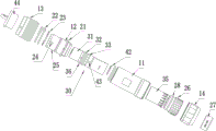
Fig. 1 is a schematic structural diagram of embodiment 1 of the connector of the present invention, which is a plug connector with a two-core structure, and a plug dust cap is omitted;
FIG. 2 is an exploded view of FIG. 1;
FIG. 3 is a schematic view of the structure of the insert member of FIG. 2;
FIG. 4 is a left side view of FIG. 1;
fig. 5 is a schematic structural diagram of embodiment 2 of the connector of the present invention, which is a socket connector with a two-core structure;
FIG. 6 is an exploded view of FIG. 5;
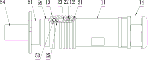
fig. 7 is a schematic structural view of an embodiment of the connector assembly of the present invention, wherein the plug connector and the receptacle connector are not inserted in place;
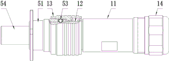
FIG. 8 is a schematic view of the plug connector of FIG. 7 in position with the receptacle connector;
fig. 9 is a schematic structural view of embodiment 3 of the connector of the present invention, which shows a plug contact arrangement structure of a plug connector with a three-core structure;
the names of the components corresponding to the corresponding reference numerals in the drawings are: 11-straight sleeve, 12-spline housing, 13-connecting nut, 14-tail nut, 21-external annular flange, 22-spring, 23-nut snap spring, 24-plug lug, 25-ring groove, 26-compression ring, 27-cable seal ring, 28-O-ring, 30-plug side plug core component, 31-plug side insulator, 32-plug side seal rubber gasket, 33-plug side centralizer, 34-plug contact, 35-insulation bushing, 36-annular lug, 37-crimping screw, 41-stop step, 42-plug core snap spring, 43-centralizer lug, 44-plug dust cap, 51-socket housing, 52-socket side plug core component, 53-locking ball, 54-socket side insulator, 55-socket side sealing rubber gasket, 56-insulating pressing plate, 57-socket core body clamp spring, 58-plug sealing ring, 59-circumferential color band, 510-socket contact element, 511-socket dust cover and 60-cable.
Detailed Description
In order to make the objects, technical solutions and advantages of the present invention more clearly understood, the present invention is further described in detail below with reference to the accompanying drawings and embodiments. It should be understood that the specific embodiments described herein are for purposes of illustration only and are not intended to limit the invention, i.e., the described embodiments are only some, but not all embodiments of the invention. The components of embodiments of the present invention, as generally described and illustrated in the figures herein, may be arranged and designed in a wide variety of different configurations.
Thus, the following detailed description of the embodiments of the present invention, presented in the accompanying drawings, is not intended to limit the scope of the invention, as claimed, but is merely representative of selected embodiments of the invention. Based on the embodiment of the present invention, all other embodiments obtained by the person skilled in the art without creative work belong to the protection scope of the present invention.
It is noted that relational terms such as the terms first and second, and the like, may be used solely to distinguish one entity or action from another entity or action without necessarily requiring or implying any actual such relationship or order between such entities or actions. Also, the terms "comprises," "comprising," or any other variation thereof, are intended to cover a non-exclusive inclusion, such that a process, method, article, or apparatus that comprises a list of elements does not include only those elements but may include other elements not expressly listed or inherent to such process, method, article, or apparatus. Without further limitation, the statement that "comprises an … …" is intended to indicate that there are additional elements of the same process, method, article, or apparatus that comprise the element.
In the description of the present invention, unless otherwise expressly specified or limited, the terms "mounted," "connected," and "connected" when they are used are to be construed broadly, e.g., as meaning either a fixed connection, a removable connection, or an integral connection; can be mechanically or electrically connected; either directly or indirectly through intervening media, or may be interconnected between two elements. The specific meaning of the above terms in the present invention can be understood by those skilled in the art from the specific situation.
In the description of the present invention, unless otherwise explicitly specified or limited, the term "provided" may be used in a broad sense, for example, the object of "provided" may be a part of the body, or may be arranged separately from the body and connected to the body, and the connection may be a detachable connection or a non-detachable connection. The specific meaning of the above terms in the present invention can be understood by those skilled in the art from the specific situation.
The present invention will be described in further detail with reference to examples.
The utility model discloses embodiment 1 of well connector:
as shown in fig. 1 to 4, the connector is a plug connector of a two-core structure, and includes a plug housing and a plug-side ferrule member 30. The plug housing comprises a main housing formed by a straight sleeve 11 and a splined housing 12, and further comprises a coupling nut 13 and a tail nut 14. The plug-side ferrule member 30 is positioned in the inner bore of the plug housing in the front-rear direction, which is the insertion and extraction direction of the connector, and the insertion and extraction direction is front.
As shown in fig. 1, 2 and 3, the spline housing 12 is provided with external threads at the rear end thereof, the straight sleeve 11 is provided with internal threads at the front end thereof, and the straight sleeve 11 is screwed on the spline housing 12; the connecting nut 13 is sleeved on the spline shell 12 from front to back, the connecting nut 13 can move back and forth on the spline shell 12, an annular outer flange 21 is arranged at the rear end of the connecting nut 13, a spring 22 is arranged between the annular outer flange 21 and the connecting nut 13 and used for pushing the connecting nut 13 forwards, clamp spring grooves are formed in the outer peripheral surface of the spline shell 12 and the inner wall of the connecting nut 13, and the connecting nut 13 is positioned on the spline shell 12 through a nut clamp spring 23 to prevent the connecting nut from being separated from the spline shell 12 under the action of the spring 22. In addition, as shown in fig. 2 and 4, two inserting convex keys 24 are arranged at the front end of the spline housing 12, and the two inserting convex keys 24 are arranged at two ends of the spline housing 12 in the diameter direction and are used for being matched with key grooves on the socket connector to realize circumferential positioning of the plug connector and the socket connector. In order to realize the locking with the socket connector, the spline housing 12 is further provided with an annular groove 25, the annular groove 25 is matched with the connecting nut 13, and a locking ball 53 structure is formed on the plug connector. As fig. 2, in order to operate connection nut 13, be equipped with convex-concave structure on connection nut 13's the outer peripheral surface, concave-convex structure is formed by circumference ring slot in this embodiment, can increase the frictional force that the operator pulled connection nut 13, has promoted the operation and has felt the experience, reduces the unblock degree of difficulty. The locking of the plug connector and the receptacle connector by the locking ball 53 is a common locking method for connectors and will not be described in detail here.
As shown in fig. 1 and 2, a radially deformable clamping ring 26 is mounted at the rear end of the inner hole of the straight sleeve 11, and a cable sealing ring 27 is arranged in the clamping ring 26. Tail nut 14 is threaded onto the end of straight sleeve 11 and has an internal taper for radially contracting clamp ring 26 when moved forward to seal cable seal ring 27 against cable 60. The cable sealing ring 27 can be selected and replaced according to the specification of the cable 60. In order to improve the sealing performance, an O-ring 28 is further provided on the outer circumferential surface of the pressing ring 26. In other embodiments, the straight sleeve 11 and the compression ring 26 may be combined into a single unit, and the O-ring 28 on the compression ring 26 may be eliminated.
As shown in fig. 3, the plug-side ferrule member 30 includes a plug-side insulator 31, a plug-side sealing rubber 32, and a plug-side centering body 33, which are sequentially arranged in series; the plug-side ferrule member 30 further includes plug contacts 34 for plugging with the receptacle contacts 510 on the receptacle connector to achieve the conduction of the wires; the plug-side insulator 31, the plug-side sealing rubber gasket 32, and the plug-side righting body 33 are provided with through holes penetrating in the front-rear direction for inserting the plug contacts 34.
The plug-side insulator 31 is positioned radially inside the plug housing for supporting the contact pieces. As shown in fig. 1, the plug-side sealing rubber gasket 32 forms a sealing rubber body, and the through hole thereof is a sealing fit hole for the contact to pass through and to be in sealing fit with the outer peripheral surface of the contact; the plug-side sealing rubber gasket 32 also has a sealing outer peripheral surface for sealing and matching with the inner hole wall of the plug housing; in this way, the axial two sides of the plug side sealing rubber gasket 32 can be isolated by the plug side sealing rubber gasket 32, so that the waterproof purpose is achieved, and liquid is prevented from entering the insertion end face of the connector from the damaged part of the outer skin of the cable 60; in addition, when the connector is not in an inserting state, the inserting face is accidentally met with water, and water cannot penetrate into the tail of the plug, so that the connector is convenient and quick to clean. The through hole on the plug side righting body 33 forms a contact positioning hole for righting the contact, so that the deflection of the contact when the cable 60 is pulled is reduced, the sealing colloid caused by the deflection of the tail end of the contact under the stress is prevented from sealing failure, and the contact can be prevented from being pulled off from the tail of the connector along with the cable under the external force.
According to needs, still be equipped with insulating bush 35 in the straight sleeve 11, insulating bush 35 rear end has the fluting along the circumference equipartition, can shrink and warp to be equipped with the boss on the rear end outer peripheral face, can the joint location in straight sleeve 11. Of course, the insulating bush 35 may not be provided as required.
The pore wall of sealed mating hole with all be equipped with annular bulge 36 more than two on the sealed peripheral face, annular bulge 36 extends along circumference for form more than two sealedly, thereby promote sealed effect. Preferably, the annular protrusion 36 has a semi-circular cross-section, although other shapes, such as rectangular and trapezoidal, are possible in other embodiments.
As shown in fig. 3, the plug contact 34 is provided with a crimping screw 37 for connecting with a cable 60. Of course, in other embodiments, the cable 60 may be connected to the plug contact 34 using other connection means conventional in the art, such as soldering, crimping terminal crimping, etc.
As shown in fig. 1, a stopping step 41 is arranged on one side of the plug-side plug-in core component 30 in the front-back direction on the plug housing, and a clamp spring groove is arranged on the other side of the plug housing, one end of the plug-side plug-in core component 30 in the front-back direction is positioned by the stopping step 41, and the other end of the plug-side plug-in core component is axially positioned by a plug core clamp spring 42 arranged in the clamp spring groove; correspondingly, the outer peripheral surface of the plug-side righting body 33 is also provided with a snap spring groove. In addition, the outer peripheral surface of the plug side righting body 33 is provided with a righting body convex key 43 extending forwards and backwards, the inner wall of the straight sleeve 11 is provided with a key groove, and the key groove is positioned behind a clamp spring groove of the plug side righting body 33 and can be matched with the righting body convex key 43 to realize circumferential positioning. The outer peripheral surface of the plug side righting body 33 is also provided with a sealing ring groove behind the righting body convex key 43 for an O-shaped ring to be installed. It should be noted that, in the drawings, a snap spring groove corresponding to the plug core snap spring 42 on the straight sleeve 11 intersects with a key groove on the inner wall of the straight sleeve 11.
Because the water inlet of the inserting and combining surface is not worried about to be difficult to clean, a common dustproof cover can be selected, a matched waterproof sealing cover is not needed, and the connector structure is favorably simplified and the cost is reduced. In this embodiment, as shown in fig. 2, the plug connector further includes a plug dust cover 44, which is only used for dust protection before the connector assembly is plugged, and does not need to satisfy the waterproof requirement.
In addition, the plug connector is provided with two plug contacts 34, the diameter of the part where each plug contact 34 is matched with the sealant is 1.6 ± 0.2mm, and correspondingly, as shown in fig. 4, the center distance L1 between the two plug contacts 34 is 5.6 ± 0.5 mm. In other embodiments, as an optimal solution, the diameter of the mating portion of each plug contact 34 and the sealant may also be 3.15 ± 0.2mm or 4.5 ± 0.2mm, and correspondingly, the center distance between the two plug contacts 34 is 8.1 ± 0.5mm or 12 ± 0.5mm, respectively. By adopting the diameter of the plug contact 34 and the center distance of the contact, the connector is embodied under the requirement of the corresponding common working current index, the maximum and minimum appearance size can be realized in the range of the adapting wire diameter, and the sealing performance is most stable.
The utility model discloses embodiment 2 of well connector:
as shown in fig. 5 and 6, the receptacle connector of the connector in the present embodiment is adapted to the plug connector in embodiment 1. The socket connector comprises a socket shell 51 and a socket side plug part 52, wherein the socket shell 51 is a square disc shell and is provided with an inner hole, and the socket side plug part 52 is arranged in the inner hole of the square disc shell.
The square plate shell is provided with a lock ball hole, a lock ball 53 is arranged in the lock ball hole, and a lock ball structure is formed at the end of the socket connector and is matched with the lock ball structure on the plug connector.
The socket-side plug member 52 includes a socket-side insulator 54, a socket-side sealing rubber gasket 55 and an insulating pressure plate 56, which are sequentially arranged in the front-rear direction, and the three structures are similar to the plug-side plug member 30, and also have through holes penetrating in the front-rear direction for the socket contact 510 to be embedded therein, and similarly, the socket-side sealing rubber gasket 55 is provided with a sealing matching hole and a sealing outer peripheral surface; the insulating pressing plate 56 is a socket side righting body, and a backward step surface is arranged on the rear end surface and used for being in blocking fit with the socket core body clamp spring 57. Of course, the inner hole wall of the socket housing 51 is provided with a matching snap spring groove. The hole of socket connector forms the spliced eye, is equipped with grafting sealing ring 58 in the spliced eye, and grafting sealing ring 58 has the sealed face of step, and the sealed face of step includes axial seal face and radial seal face, respectively with the sealed cooperation of grafting end terminal surface and the outer peripheral face of plug connector, specifically, in this embodiment, with the terminal surface and the outer peripheral face sealed cooperation of spline shell 12 front end.
In addition, a circumferential color tape 59 is further arranged on the outer peripheral surface of the socket shell 51, the circumferential color tape 59 extends along the circumferential direction and is arranged at a set position along the axial direction of the socket shell 51, and when the plug connector is plugged in place, the circumferential color tape 59 is shielded by the plug shell of the plug connector to indicate that the plug connector and the socket connector are plugged in place.
Due to the fact that the socket side sealing rubber gasket 55 is arranged, after the socket connector is installed in place on the panel of the equipment, even if the socket connector is in a non-plugging state, external water cannot enter the equipment, and the protection performance of the equipment is improved. The structure also enables the socket connector to select a common dustproof cover without a matched waterproof sealing cover. In this embodiment, the receptacle connector further includes a receptacle dust cap 511, which is only used for dust protection before the connector assembly is plugged, and does not need to satisfy the waterproof requirement.
In the socket connector, the diameter of the part where the socket contact 510 is matched with the sealing colloid and the center distance of the socket contact 510 are respectively the same as the diameter of the plug contact 34 and the center distance of the contact.
Referring to fig. 7 and 8, when the plug-in locking is required, only the straight sleeve 11 or the tail nut 14 needs to be pushed, and at this time, the locking ball 53 at the socket end is jacked up by the outer wall of the front end of the spline housing and contacts with the step surface of the connecting nut 13 to force the connecting nut 13 to axially displace relative to the spline housing. When the ring groove 25 of the spline housing moves to the position right below the lock ball 53, the lock ball 53 is displaced by the reaction force of the connecting nut 13 and falls into the ring groove 25; the coupling nut 13 is now rapidly returned to its original position under the force of the spring 22. In a locking state, the locking ball 53 is positioned in the annular groove 25 of the spline housing and is blocked by the inner wall of the connecting nut 13, and the pre-compression force of the spring 22 ensures that the connecting nut 13 does not retreat, so that stable and reliable locking is realized. Before the socket is inserted in place, the circumferential color band 59 at the socket end is exposed and can be seen; after the plug-in position is achieved, the circumferential color band 59 is covered by the connecting nut 13, and the in-position mark is obvious.
When the unlocking is needed, only the connecting nut 13 needs to be pulled successively, the diameter of the inner wall surface of the connecting nut 13 contacted with the locking ball 53 is increased, the spline shell is forced by the spring 22 to move in the same direction, and the annular groove 25 of the spline shell pushes the locking ball 53 to ascend and finally separate from the annular groove 25, so that the unlocking is realized. In conclusion, the push-pull locking mode has a simple structure, is stable and reliable in looseness prevention, does not need an operation torsion space, and is convenient for meeting the requirements of equipment miniaturization and interface densification; the push-pull locking mode is simple to operate and can be in place in one step, the insertion reliability is more prominent in a narrow installation space compared with connection modes such as threads and bayonets, and the sealing failure risk caused by the fact that the insertion is not in place can be greatly reduced.
The utility model discloses embodiment 3 of well connector:
the difference between the present embodiment and embodiment 1 is that, in embodiment 1, the plug connector is a two-core connector, while in this embodiment, the plug connector is a three-core connector, three plug contacts 34 are parallel to each other, the center lines of the three are arranged in an equilateral triangle, the diameter of the mating portion of each plug contact 34 and the sealant is 1.6 ± 0.2mm, and the center distance L2 between any two contacts is 5.2 ± 0.5 mm.
In other embodiments, for a three-core connector, as shown in fig. 9, the diameter of the mating portion of each plug contact 34 and the sealant may also be 2.4 ± 0.2mm, and correspondingly, the center-to-center distance between any two plug contacts 34 is 6.4 ± 0.5 mm.
The utility model discloses embodiment 4 of well connector:
the difference between this embodiment and embodiment 1 is that in embodiment 1, the sealing colloid is disposed separately from the insulator and arranged in front of and behind the insulator, but in this embodiment, the insulator is made of an elastic material, and the sealing colloid is formed by corresponding sections of the insulator.
In other embodiments, the insulator and the centralizing body can both adopt elastic materials, and form an integral elastomer with the sealant, and the sealant is formed by corresponding sections of the elastomer; the ferrule member is now composed of only two pieces, an elastomer and a contact.
In addition, in other embodiments, the sealing gel may also be disposed at the forwardmost or rearwardmost end of the ferrule member.
The utility model discloses embodiment 5 of well connector:
the difference between this embodiment and embodiment 1 is that in embodiment 1, the sealing colloid is a sealing rubber mat, and in this embodiment, the sealing colloid is a glue solution solidified between the insulator, the righting body, and the shell, and during manufacturing, the insulator is first loaded into the shell, then a certain amount of glue solution is poured, and finally the righting body is loaded, and the glue solution is fully contacted with the insulator, the shell, and the righting body, and the sealing colloid can be formed after the glue solution is solidified. The glue filling has the defects that the glue solution curing period is prolonged, so that the production period is obviously prolonged; in addition, the colloid has the possibility of generating gaps due to expansion with heat and contraction with cold caused by temperature change in the outdoor long-term use process, and finally sealing failure can be caused, but the colloid can be in more sufficient sealing contact under the condition that the expansion with heat and the contraction with cold of the colloid are controllable.
The utility model discloses embodiment 6 of well connector:
the difference between this embodiment and embodiment 1 is that in embodiment 1, the sealant is provided with more than two annular protrusions 36, and in this embodiment, the outer peripheral surface of the sealant is a cylindrical surface, and the annular protrusions 36 are not provided.
Of course, in other embodiments, more than three annular protrusions 36 may be provided on the sealant.
The utility model discloses well connector assembly's embodiment: embodiments of the connector include a plug connector and a receptacle connector, which are respectively the plug connector and the receptacle connector in the corresponding embodiments described above, and will not be described in detail here.
The above description is only a preferred embodiment of the present application, and not intended to limit the present application, the scope of the present application is defined by the appended claims, and all changes in equivalent structure made by using the contents of the specification and the drawings of the present application should be considered as being included in the scope of the present application.
Claims (10)
1. A connector, comprising:
a housing having an inner bore for receiving the ferrule member;
the ferrule component is positioned and arranged in an inner hole of the shell along the front-back direction, and the front-back direction is the plugging direction of the connector; the ferrule member includes:
an insulator positioned radially within the housing for supporting the contact;
the contact piece is embedded in the insulator and used for realizing circuit conduction;
it is characterized in that the preparation method is characterized in that,
the ferrule component comprises a sealing colloid which is provided with a sealing matching hole and a sealing peripheral surface;
the sealing fit hole is used for the contact part to pass through and to be in sealing fit with the peripheral surface of the contact part;
the sealing peripheral surface is used for being in sealing fit with the inner hole wall of the shell;
the sealing colloid and the insulator are arranged in front and at the back, or the sealing colloid is formed by the insulator.
2. A connector according to claim 1, wherein the wall of the sealing engagement bore and/or the outer periphery of the seal is provided with an annular projection (36), the annular projection (36) extending in the circumferential direction.
3. The connector of claim 2, wherein the sealing engagement hole has two or more annular protrusions (36) on a wall thereof and/or two or more annular protrusions (36) on an outer peripheral surface thereof.
4. The connector according to any one of claims 1 to 3, wherein the housing is provided with a stopping step (41) at one side in the front-rear direction of the ferrule member, and a snap spring groove at the other side, and one end of the ferrule member in the front-rear direction is positioned by the stopping step (41) and the other end is positioned by a snap spring arranged in the snap spring groove.
5. A connector according to any one of claims 1 to 3, wherein the ferrule member includes a righting body that is righted within the internal bore of the housing at the rear end of the ferrule member; the centralizing body is internally provided with a contact element positioning hole for centralizing the contact element along the radial direction.
6. The connector of claim 5, wherein the centralizing body is spaced forward and rearward of the insulator, and the sealant is disposed between the insulator and the centralizing body.
7. The connector of claim 6, wherein the sealing compound is a sealing compound gasket fitted between the insulator and the centralizing body, or a compound cured between the insulator, the centralizing body and the housing.
8. A connector according to any one of claims 1 to 3, wherein the connector is provided with a plug hole, a plug sealing ring (58) is arranged in the plug hole, the plug sealing ring (58) has a stepped sealing surface, and the stepped sealing surface comprises an axial sealing surface and a radial sealing surface which are respectively in sealing fit with the end face and the outer peripheral surface of the plug end of the adapter connector.
9. A connector according to any one of claims 1 to 3, wherein the connector is provided with two contact members, the diameter of the part where each contact member is matched with the sealant is 1.6 ± 0.2mm, 3.15 ± 0.2mm or 4.5 ± 0.2mm, and the center distance between the two contact members is 5.6 ± 0.5mm, 8.1 ± 0.5mm or 12 ± 0.5mm in a one-to-one correspondence manner;
or: the connector is provided with three contact elements, the three contact elements are parallel to each other, the central lines of the three contact elements are arranged in an equilateral triangle, the diameter of the matching part of each contact element and the sealing colloid is 1.6 +/-0.2 mm or 2.4 +/-0.2 mm, and the center distance between any two contact elements is 5.2 +/-0.5 mm and 6.4 +/-0.5 mm in one-to-one correspondence.
10. Connector assembly comprising a plug connector and a socket connector, characterized in that the plug connector and/or the socket connector is a connector according to any one of claims 1 to 9.
Priority Applications (1)
| Application Number | Priority Date | Filing Date | Title |
|---|---|---|---|
| CN202022120430.0U CN213242937U (en) | 2020-09-24 | 2020-09-24 | Connector and connector assembly |
Applications Claiming Priority (1)
| Application Number | Priority Date | Filing Date | Title |
|---|---|---|---|
| CN202022120430.0U CN213242937U (en) | 2020-09-24 | 2020-09-24 | Connector and connector assembly |
Publications (1)
| Publication Number | Publication Date |
|---|---|
| CN213242937U true CN213242937U (en) | 2021-05-18 |
Family
ID=75876888
Family Applications (1)
| Application Number | Title | Priority Date | Filing Date |
|---|---|---|---|
| CN202022120430.0U Active CN213242937U (en) | 2020-09-24 | 2020-09-24 | Connector and connector assembly |
Country Status (1)
| Country | Link |
|---|---|
| CN (1) | CN213242937U (en) |
-
2020
- 2020-09-24 CN CN202022120430.0U patent/CN213242937U/en active Active
Similar Documents
| Publication | Publication Date | Title |
|---|---|---|
| US7291033B2 (en) | Snap-on and self-lock RF coaxial connector | |
| CA2557157C (en) | Bulkhead socket for a co-axial plug and socket connector | |
| JP4581947B2 (en) | connector | |
| US3808580A (en) | Self-locking coupling nut for electrical connectors | |
| US7458858B2 (en) | Electrical connector | |
| GB2477987A (en) | Locking right-angled electrical connector | |
| CN110676651A (en) | High-voltage connector with secondary locking structure | |
| US4857007A (en) | Molded environmental seal for electrical connection | |
| CN109119818B (en) | Circular connector and connector assembly | |
| CN213242937U (en) | Connector and connector assembly | |
| CN112615204B (en) | Electrical connection assembly | |
| CN108683025A (en) | A kind of high-performance high-tension connector | |
| CN210692915U (en) | Cold-press-connection quick-plugging electric connector shielding sealing structure | |
| CN217087011U (en) | Connector assembly | |
| CN216563639U (en) | A kind of interface unit | |
| CN112290301B (en) | Flexible push-pull quick-locking connector | |
| CN210957173U (en) | Ethernet fast plugging electric connector | |
| CN210926457U (en) | Modularization cold-pressed quick plug-pull electric connector | |
| CN109713514B (en) | Reusable flame-proof socket | |
| CN112563809A (en) | Bending connector | |
| CN109586102A (en) | Plug-type locking connector component | |
| CN213905637U (en) | Electric spark prevention socket | |
| CN218242435U (en) | Connector assembly and connector | |
| CN218940166U (en) | Connector and connector assembly | |
| CN214957595U (en) | Thread locking connector |
Legal Events
| Date | Code | Title | Description |
|---|---|---|---|
| GR01 | Patent grant | ||
| GR01 | Patent grant |