CN213230733U - Melt and spout filter material wind roller angle adjusting device - Google Patents
Melt and spout filter material wind roller angle adjusting device Download PDFInfo
- Publication number
- CN213230733U CN213230733U CN202021900335.6U CN202021900335U CN213230733U CN 213230733 U CN213230733 U CN 213230733U CN 202021900335 U CN202021900335 U CN 202021900335U CN 213230733 U CN213230733 U CN 213230733U
- Authority
- CN
- China
- Prior art keywords
- shaped
- arc
- roller
- rotating
- sliding
- Prior art date
- Legal status (The legal status is an assumption and is not a legal conclusion. Google has not performed a legal analysis and makes no representation as to the accuracy of the status listed.)
- Active
Links
Images


Abstract
The utility model discloses a melt and spout filtering material winding roller angle adjusting device, including rectangular base, the rectangular base top is equipped with slide adjusting mechanism, the slide adjusting mechanism upper end is equipped with initiative slewing mechanism. The utility model has the advantages that the receiving angle of the receiving roller can be accurately and laborsavingly adjusted through the action of the sliding adjusting mechanism, the operation of manually moving the base is avoided, and the labor-saving effect is achieved; the receiving roller can stably rotate under the action of the driving rotating mechanism, and is convenient to disassemble.
Description
Technical Field
The utility model relates to a non-woven fabrics production technical field, more specifically say, relate to a melt-blown filter material winding roller angle adjusting device.
Background
Non-woven fabrics, also known as non-woven fabrics, are sheets, fiber webs or batts made of oriented or randomly arranged fibers by friction, cohesion or adhesion, or a combination of these methods, and have the characteristics of moisture resistance, air permeability, flexibility, low price, recyclability, etc.;
the non-woven fabric is required to be wound on the receiving roller during melt-blown production of the non-woven fabric, so that the non-woven fabric is convenient to move to the next procedure, the receiving roller is placed at the upper end of the support, and the receiving roller is required to be frequently taken or put down, so that the angle between the support and the receiving roller is deviated to a certain extent, and the non-woven fabric is deviated during winding; the traditional receiving roller is directly placed at the upper end of the bracket, and the gears are not tightly meshed, so that the slipping phenomenon is easy to occur.
SUMMERY OF THE UTILITY MODEL
To above defect, the utility model provides a melt and spout filtering material winding roller angle adjusting device to the solution problem.
In order to achieve the above purpose, the utility model adopts the following technical scheme:
a device for adjusting the angle of a winding roller of a melt-blown filter material comprises a rectangular base, wherein a sliding adjusting mechanism is arranged above the rectangular base, and the upper end of the sliding adjusting mechanism is provided with an active rotating mechanism;
the sliding adjusting mechanism comprises arc-shaped slideways at two ends of the upper surface of a rectangular base, sliding blocks are mounted on one sides of the arc-shaped slideways and are connected with the arc-shaped slideways in a sliding mode, arc-shaped worm wheels are mounted on the side surfaces of the sliding blocks, first bearings are mounted on one sides of the arc-shaped slideways, first rotating shafts are mounted on inner rings of the first bearings, worms meshed with the arc-shaped worm wheels are mounted at one ends of the rotating shafts, first bevel gears are mounted at the other ends of the first rotating shafts, second bearings are mounted on one sides of the first bevel gears and fixedly connected with the rectangular base, second rotating shafts are mounted on inner rings of the second bearings, second bevel;
the driving rotating mechanism comprises a supporting rod on the upper surface of a sliding block, a U-shaped block is mounted at the upper end of the supporting rod, a pulley is mounted on the side surface of the U-shaped block, an I-shaped roller is arranged at the upper end of the U-shaped block and is connected with the pulley in a sliding mode, a first transmission gear is mounted on the side surface of the I-shaped roller, a rotating motor is mounted at the upper end of the supporting rod, a second transmission gear meshed with the first transmission gear is mounted at the rotating end of the rotating motor, a limiting strip is mounted on the inner ring of the I-shaped roller, a receiving roller is mounted on the inner ring of the.
Further, an arc-shaped cover plate is installed at one end of the upper surface of the U-shaped block and is hinged to the U-shaped block, a pinch roller is installed on the lower surface of the arc-shaped cover plate, a threaded shaft is installed at the other end of the upper surface of the U-shaped block, the lower end of the threaded shaft is hinged to the U-shaped block, and a special-shaped nut is installed at the upper end of the threaded shaft.
Furthermore, one end of the arc-shaped cover plate is provided with a notch.
Furthermore, the outer surface of the receiving roller is provided with non-woven fabrics.
The utility model has the advantages that: the receiving angle of the receiving roller can be accurately and laborsavingly adjusted under the action of the sliding adjusting mechanism, so that the operation of manually moving the base is avoided, and the labor-saving effect is achieved; the receiving roller can stably rotate under the action of the driving rotating mechanism, and is convenient to disassemble.
Drawings
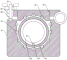
FIG. 1 is a schematic structural view of a device for adjusting the angle of a winding roller of a melt-blown filter material according to the present invention;
FIG. 2 is a schematic top view of the slide adjustment mechanism;
FIG. 3 is a side view schematic of a U-shaped block;
FIG. 4 is a partial schematic view of the active rotation mechanism;
in the figure, 1, a rectangular base; 2. an arc-shaped slideway; 3. a slider; 4. an arc-shaped worm wheel; 5. a first bearing; 6. rotating a first shaft; 7. a worm; 8. a first bevel gear; 9. a second bearing; 10. a second rotating shaft; 11. a second bevel gear; 12. a connecting shaft; 13. a rotating wheel; 14. a support bar; 15. a U-shaped block; 16. a pulley; 17. an I-shaped roller; 18. a first transmission gear; 19. a rotating electric machine; 20. a second transmission gear; 21. a limiting strip; 22. a receiving roller; 23. a limiting groove; 24. an arc-shaped cover plate; 25. a pinch roller; 26. a threaded shaft; 27. a special-shaped nut; 28. opening the gap; 29. a nonwoven fabric.
Detailed Description
The utility model is described in detail with reference to the accompanying drawings, as shown in fig. 1-4, the angle adjusting device for the winding roller of the melt-blown filter material comprises a rectangular base 1, a sliding adjusting mechanism is arranged above the rectangular base 1, and an active rotating mechanism is arranged at the upper end of the sliding adjusting mechanism;
the sliding adjusting mechanism comprises arc-shaped slideways 2 at two ends of the upper surface of a rectangular base 1, sliding blocks 3 are mounted on one sides of the arc-shaped slideways 2, the sliding blocks 3 are connected with the arc-shaped slideways 2 in a sliding mode, arc-shaped worm wheels 4 are mounted on the side surfaces of the sliding blocks 3, bearings 5 are mounted on one sides of the arc-shaped slideways 2, rotating shafts 6 are mounted on inner rings of the bearings 5, worms 7 meshed with the arc-shaped worm wheels 4 are mounted at one ends of the rotating shafts 6, bevel gears 8 are mounted at the other ends of the rotating shafts 6, bearings 9 are mounted on one sides of the bevel gears 8, the bearings 9 are fixedly connected with the rectangular base 1, rotating shafts 10 are mounted on inner rings of the bearings 9, bevel gears 11 meshed with the bevel gears 8 are mounted at;
the driving rotating mechanism comprises a supporting rod 14 on the upper surface of the sliding block 3, a U-shaped block 15 is installed at the upper end of the supporting rod 14, a pulley 16 is installed on the side surface of the U-shaped block 15, an I-shaped roller 17 is arranged at the upper end of the U-shaped block 15, the I-shaped roller 17 is in sliding connection with the pulley 16, a first transmission gear 18 is installed on the side surface of the I-shaped roller 17, a rotating motor 19 is installed at the upper end of the supporting rod 14, a second transmission gear 20 meshed with the first transmission gear 18 is installed at the rotating end of the rotating motor 19, a limiting strip 21 is installed on the inner ring of the I-shaped roller 17, a receiving roller 22 is installed on the inner ring of the I-shaped.
Arc apron 24 is installed to U type piece 15 upper surface one end, and arc apron 24 is articulated with U type piece 15, and surface mounting has pinch roller 25 under the arc apron 24, and threaded shaft 26 is installed to the U type piece 15 upper surface other end, and threaded shaft 26 lower extreme is articulated with U type piece 15, and heterotypic nut 27 is installed to threaded shaft 26 upper end.
One end of the arc cover plate 24 is provided with a gap 28.
The receiving roll 22 is provided with a nonwoven 29 on its outer surface.
In this embodiment, the electric equipment of the equipment is controlled by an external controller, when the receiving angle of the receiving roller 22 needs to be adjusted, the rotating wheel 13 is manually rotated, the rotation of the rotating wheel 13 drives the connecting shaft 12 and the second bevel gear 11 to rotate, the rotation of the second bevel gear 11 drives the first bevel gear 8 to rotate, the rotation of the first bevel gear 8 drives the worm 7 to rotate, the worm 7 drives the arc worm wheel 4 and the sliding block 3 to slide in the arc slideway 2, the purpose of adjusting the position of the sliding block 3 is realized, the receiving roller 22 is supported by the sliding block 3 and the supporting rod 14, so the movement of the sliding block 3 indirectly drives the receiving roller 22 to adjust; the first rotating shaft 6 and the second rotating shaft 10 can stably rotate under the action of the first bearing 5 and the second bearing 9, and the sliding block 3 can slide in the opposite direction through the transmission of the worm 7 and the arc-shaped worm wheel 4, so that the adjustment efficiency is improved;
after the adjustment is finished, the I-shaped roller 17 is sleeved at two ends of the receiving roller 22, the limiting strip 21 is attached to the limiting groove 23, then the I-shaped rollers 17 at two ends are placed at the upper end of the U-shaped block 15, the first transmission gear 18 is engaged with the second transmission gear 20 at the moment, the U-shaped block 15 is clamped at the center of the I-shaped roller 17 to prevent the receiving roller 22 from sliding left and right, then the arc-shaped cover plate 24 is manually buckled to enable the pressing wheel 25 to be attached to the upper end of the I-shaped roller 17, then the threaded shaft 26 is rotated to the position of the notch 28 and the special-shaped nut 27 is screwed, as shown in figure 3, under the action of the pulley 16 and the pinch roller 25, the I-shaped roller 17 can stably rotate, then the controller controls the rotating motor 19 to rotate, the rotating motor 19 rotates to drive the second transmission gear 20, the first transmission gear 18 and the I-shaped roller 17 to rotate, and drives the receiving roller 22 to rotate, so that the receiving roller 22 winds the non-woven fabric 29.
Above-mentioned technical scheme has only embodied the utility model discloses technical scheme's preferred technical scheme, some changes that this technical field's technical personnel probably made to some parts wherein have all embodied the utility model discloses a principle belongs to within the protection scope of the utility model.
Claims (4)
1. The angle adjusting device for the winding roller of the melt-blown filter material comprises a rectangular base (1), and is characterized in that a sliding adjusting mechanism is arranged above the rectangular base (1), and an active rotating mechanism is arranged at the upper end of the sliding adjusting mechanism;
the sliding adjusting mechanism comprises arc-shaped slideways (2) at two ends of the upper surface of a rectangular base (1), a sliding block (3) is installed on one side of each arc-shaped slideway (2), the sliding block (3) is in sliding connection with the arc-shaped slideways (2), an arc-shaped worm wheel (4) is installed on the side surface of each sliding block (3), a first bearing (5) is installed on one side of each arc-shaped slideway (2), a first rotating shaft (6) is installed on the inner ring of each first bearing (5), a worm (7) meshed with the arc-shaped worm wheel (4) is installed at one end of the first rotating shaft (6), a first bevel gear (8) is installed at the other end of the first rotating shaft (6), a second bearing (9) is installed on one side of the first bevel gear (8), the second bearing (9) is fixedly connected with the rectangular base (1), a second rotating shaft (10), a connecting shaft (12) is arranged on the side surface of the second bevel gear (11), and a rotating wheel (13) is arranged at one end of the connecting shaft (12);
the driving rotating mechanism comprises a supporting rod (14) on the upper surface of a sliding block (3), a U-shaped block (15) is installed at the upper end of the supporting rod (14), a pulley (16) is installed on the side surface of the U-shaped block (15), an I-shaped roller (17) is arranged at the upper end of the U-shaped block (15), the I-shaped roller (17) is in sliding connection with the pulley (16), a first transmission gear (18) is installed on the side surface of the I-shaped roller (17), a rotating motor (19) is installed at the upper end of the supporting rod (14), a second transmission gear (20) meshed with the first transmission gear (18) is installed at the rotating end of the rotating motor (19), a limiting strip (21) is installed on the inner ring of the I-shaped roller (17), a receiving roller (22) is installed on the inner ring of the I-shaped roller (17), limiting grooves.
2. The angle adjusting device for the winding roller of the melt-blown filter material as claimed in claim 1, wherein an arc-shaped cover plate (24) is mounted at one end of the upper surface of the U-shaped block (15), the arc-shaped cover plate (24) is hinged to the U-shaped block (15), a pressing wheel (25) is mounted at the lower surface of the arc-shaped cover plate (24), a threaded shaft (26) is mounted at the other end of the upper surface of the U-shaped block (15), the lower end of the threaded shaft (26) is hinged to the U-shaped block (15), and a special-shaped nut (27) is mounted at the upper end.
3. The angle adjusting device of a winding roller of melt-blown filter material as claimed in claim 2, wherein the arcuate cover plate (24) has a cutout (28) formed at one end thereof.
4. The device for adjusting the angle of a take-up roll of melt-blown filter material as claimed in claim 1, wherein the receiving roll (22) is provided on its outer surface with a nonwoven fabric (29).
Priority Applications (1)
| Application Number | Priority Date | Filing Date | Title |
|---|---|---|---|
| CN202021900335.6U CN213230733U (en) | 2020-09-05 | 2020-09-05 | Melt and spout filter material wind roller angle adjusting device |
Applications Claiming Priority (1)
| Application Number | Priority Date | Filing Date | Title |
|---|---|---|---|
| CN202021900335.6U CN213230733U (en) | 2020-09-05 | 2020-09-05 | Melt and spout filter material wind roller angle adjusting device |
Publications (1)
| Publication Number | Publication Date |
|---|---|
| CN213230733U true CN213230733U (en) | 2021-05-18 |
Family
ID=75871040
Family Applications (1)
| Application Number | Title | Priority Date | Filing Date |
|---|---|---|---|
| CN202021900335.6U Active CN213230733U (en) | 2020-09-05 | 2020-09-05 | Melt and spout filter material wind roller angle adjusting device |
Country Status (1)
| Country | Link |
|---|---|
| CN (1) | CN213230733U (en) |
Cited By (1)
| Publication number | Priority date | Publication date | Assignee | Title |
|---|---|---|---|---|
| CN115846469A (en) * | 2023-02-02 | 2023-03-28 | 河北锐升起重机械有限公司 | Adjustable steel plate forming device |
-
2020
- 2020-09-05 CN CN202021900335.6U patent/CN213230733U/en active Active
Cited By (1)
| Publication number | Priority date | Publication date | Assignee | Title |
|---|---|---|---|---|
| CN115846469A (en) * | 2023-02-02 | 2023-03-28 | 河北锐升起重机械有限公司 | Adjustable steel plate forming device |
Similar Documents
| Publication | Publication Date | Title |
|---|---|---|
| CN208906952U (en) | A kind of silk dedusting wrap-up | |
| CN213230733U (en) | Melt and spout filter material wind roller angle adjusting device | |
| CN114348728B (en) | Glass fiber check cloth coiling mechanism | |
| CN111747180B (en) | Melt-blown fabric conveying device | |
| CN110407014A (en) | A kind of easy-to-dismount wrap-up of wool fabric production | |
| CN216917951U (en) | Overall process weaving equipment | |
| CN209161055U (en) | The filter cloth wrap-up for having automatic blanking function | |
| CN217201116U (en) | Graphite alkene electric heat membrane coiling mechanism | |
| CN207759752U (en) | A kind of fiber spun-laced nonwoven fabric winding machines of ES | |
| CN206814078U (en) | A kind of lapping machine | |
| CN115961431A (en) | Carbon fiber braider is with seam limit mechanism | |
| CN213474935U (en) | A straining device for melting cloth spreading machine that spouts | |
| CN114684647A (en) | Copper foil coiling mechanism | |
| CN215516019U (en) | Full-automatic rolling machine capable of preventing deviation in positioning | |
| CN207713085U (en) | A kind of non-woven fabrics up- coiler | |
| CN211141021U (en) | Double-layer cloth rolling frame of ribbon loom | |
| CN219525717U (en) | Winding mechanism for non-woven fabrics | |
| CN216996899U (en) | Coiling mechanism is used in non-woven fabrics production | |
| CN216736818U (en) | Compression roller for non-woven fabric production | |
| CN210012384U (en) | Coiling mechanism is used in non-woven fabrics processing | |
| CN212315096U (en) | Melt-blown machine with automatic receiving agencies | |
| CN215159907U (en) | Chemical fiber spinning guiding device | |
| CN218231174U (en) | Convenient melt-blown fabric rolling equipment that changes a roll | |
| CN216945474U (en) | Winding equipment for fabric combined machining | |
| CN214140810U (en) | Finished product unwinding device |
Legal Events
| Date | Code | Title | Description |
|---|---|---|---|
| GR01 | Patent grant | ||
| GR01 | Patent grant |