Disclosure of Invention
In order to solve the above problems, an object of the present invention is to provide a poultry injection inversion fixing device with neck fixing and turning functions.
The utility model aims at realizing through the following technical scheme:
the utility model provides a pair of poultry injection special use is invertd fixing device with fixed and upset function of neck, include: the rotary locking device comprises a base, a stand column, a rotating shaft I, a conical sleeve assembly, a rotary locking clamping structure and a rotary locking structure;
the base is provided with two upright posts, the upright posts are hinged with rotating shafts I, and the two rotating shafts I are connected with the conical sleeve assembly; the tapered sleeve component is a tapered sleeve, two ends of the tapered sleeve component are both provided with openings, and the end part with a small caliber on the tapered sleeve component is connected with a rotary locking clamping structure;
rotatory locking screens structure includes: the clamping plate shell, the clamping plate, the rotary disc and the rotary flap are arranged on the rotary disc; the clamping plate shell is of a circular hollow structure, and a clamping plate groove is formed in the clamping plate shell; one upper end surface of two ends of the clamping plate is provided with a guide pin, and the other lower end surface of the clamping plate is provided with a rotating pin; a plurality of clamping plates are sequentially stacked in a circumferential front-back adjacent manner in the clamping plate groove, rotating pins of the clamping plates are hinged with the lower end of the clamping plate groove, guide pin grooves with radial trend are arranged at positions, corresponding to the guide pins of the upper end surface of the clamping plates, on the rotary table, guide pin sleeves are arranged in the guide pin grooves, rotating grooves are formed in the clamping plate shell, and rotating flaps penetrate through the rotating grooves and are connected with the rotary table;
the rotation locking structure includes: a rotating shaft II, a fixed ratchet plate, a movable ratchet plate, a handheld boss, a locking nut and a spring; wherein a rotation axis I is connected with rotation axis II, rotation axis II articulates on the stand, it is provided with the fixed ratchet dish around rotation axis II on I side of rotation axis to keep away from on the stand, be provided with guide way and external screw thread section on the rotation axis II, be provided with the guide block on the activity ratchet dish hole, activity ratchet dish circumference is provided with handheld boss, activity ratchet dish cover is established on rotation axis II and the guide block is installed in the guide way, activity ratchet dish can mesh with fixed ratchet dish after moving on rotation axis II, the external screw thread section at rotation axis II is established to the locking nut thread cover, the spring housing is established on rotation axis II and both ends are supported movable ratchet dish respectively, locking nut, the spring is in compression state all the time.
Further, the tapered sleeve assembly comprises: the device comprises a conical sleeve I, a conical sleeve II, a conical sleeve III and a conical sleeve IV; the conical sleeve I, the conical sleeve II, the conical sleeve III and the conical sleeve IV are sequentially connected, a closing-up step with a convex radial length is inwards arranged on the circumference of the end part of the small opening on the conical sleeve I, a plurality of locking boss abdicating grooves are uniformly arranged on the closing-up step towards the inner wall of the conical sleeve I at equal angles, and the parts of the closing-up step, which are positioned in the non-locking boss abdicating groove area, are uniformly provided with the blocking blocks with the same number as the locking boss abdicating grooves;
a plurality of locking bosses protruding outwards in the radial direction are evenly arranged at the end part of the thick caliber of the conical sleeve II in the circumferential direction, a circumferential boss protruding outwards in the radial direction is arranged on the outer wall of the conical sleeve II and located at the lower part of the locking boss, and the number of the locking bosses and the number of the locking boss yielding grooves are equal.
Furthermore, the length of the locking boss extending outwards in the radial direction is smaller than the depth of the locking boss yielding groove, the circumferential arc length of the locking boss is smaller than that of the locking boss yielding groove, and the axial distance between the circumferential boss and the locking boss is equal to the thickness of the upper necking step of the conical sleeve I.
Furthermore, the number of the locking bosses, the locking boss abdicating grooves and the number of the blocking blocks are three.
Furthermore, the conical sleeve II, the conical sleeve III and the conical sleeve IV are sequentially sleeved and arranged in a telescopic manner.
Furthermore, hemispherical convex gear clamping points are uniformly arranged on one side end face of the rotating groove at equal angles, and hemispherical concave clamping point grooves matched with the gear clamping points in shape are arranged on the corresponding side end face of the rotating valve.
Furthermore, the base is of a frame structure shaped like a Chinese character ri, and two sides of the upright post and the base are fixedly connected with support rods which are distributed obliquely.
Furthermore, the screens board is the arc, and the width of screens board equals with the width in screens board groove, and the quantity of screens board is six.
Further, the width of the guide pin slot is equal to the outer diameter of the guide pin.
Furthermore, the external thread section adopts fine threads.
The utility model discloses a poultry injection special use inversion fixing device with neck is fixed and upset function, it stirs the regional enlargies of rotation lamella unified control position board to middle passageway and shrink and reach the fixed effect of poultry neck locking screens to correspond poultry head position and be provided with rotatory locking screens structure for the poultry neck can't swing the head when injecting, is used for guaranteeing the stability and the success rate of injection. Simultaneously this rotational locking screens structure easy operation, all screens boards homoenergetic guarantee to receive and release in unison, and 360 degrees locks simultaneously in neck periphery, guarantees fixed stability. Meanwhile, the device can control the integral angle of the poultry through the rotation locking structure, can achieve the effect of real-time self-locking after angle adjustment, ensures that the poultry can be injected through the optimal angle, and is simple in operation, convenient and practical.
Detailed Description
In order to make the technical solution of the present invention better understood, the technical solution of the embodiments of the present invention will be clearly and completely described below with reference to the accompanying drawings in the embodiments of the present invention, and it is obvious that the described embodiments are only some embodiments of the present invention, not all embodiments. Based on the embodiments in the present invention, all other embodiments obtained by a person skilled in the art without creative efforts shall belong to the protection scope of the present invention.
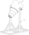
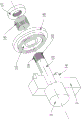
As shown in fig. 1 to 13, the utility model provides a special inverted fixing device of poultry injection with neck is fixed and upset function, include: the rotary locking device comprises a base 1, a stand column 2, a rotary shaft I3, a conical sleeve assembly, a rotary locking clamping structure and a rotary locking structure;
two upright posts 2 are arranged on the base 1, rotating shafts I3 are hinged on the upright posts 2, and the two rotating shafts I3 are connected with a conical sleeve component; the tapered sleeve component is a tapered sleeve, two ends of the tapered sleeve component are both provided with openings, and the end part with a small caliber on the tapered sleeve component is connected with a rotary locking clamping structure;
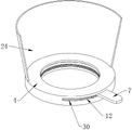
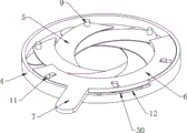
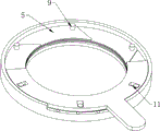
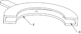
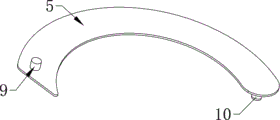
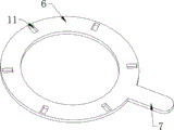
rotatory locking screens structure includes: a clamping plate shell 4, a clamping plate 5, a rotary disc 6 and a rotary flap 7; the clamping plate shell 4 is of a circular hollow structure, and a clamping plate groove 8 is formed in the clamping plate shell 4; one upper end surface of two ends of the clamping plate 5 is provided with a guide pin 9, and the other lower end surface is provided with a rotating pin 10; a plurality of clamping plates 5 are sequentially stacked in a circumferential front-back adjacent manner in a clamping plate groove 8, a rotating pin 10 of each clamping plate 5 is hinged with the lower end of the clamping plate groove 8, a guide pin groove 11 with a radial trend is arranged on the rotary table 6 corresponding to a guide pin 9 on the upper end surface of each clamping plate 5, the guide pin 9 is sleeved in the guide pin groove 11, a rotating groove 12 is formed in the clamping plate shell 4, and a rotating flap 7 penetrates through the rotating groove 12 and is connected with the rotary table 6;
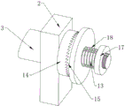
the rotation locking structure includes: a rotating shaft II 13, a fixed ratchet plate 14, a movable ratchet plate 15, a handheld boss 16, a locking nut 17 and a spring 18; one of the rotating shaft I3 is connected with the rotating shaft II 13, the rotating shaft II 13 is hinged on the upright post 2, a fixed ratchet disc 14 surrounding the rotating shaft II 13 is arranged on one side face, far away from the rotating shaft I3, of the upright post 2, a guide groove 19 and an external thread section 20 are arranged on the rotating shaft II 13, a guide block is arranged on an inner hole of the movable ratchet disc 15, a handheld boss 16 is circumferentially arranged on the movable ratchet disc 15, the movable ratchet disc 15 is sleeved on the rotating shaft II 13, the guide block is installed in the guide groove 19, the movable ratchet disc 15 can be meshed with the fixed ratchet disc 14 after moving on the rotating shaft II 13, a locking nut 17 is sleeved on the external thread section 20 of the rotating shaft II 13 in a threaded mode, a spring 18 is sleeved on the rotating shaft II 13, two ends of the spring respectively abut against the.
The utility model discloses a poultry injection special use inversion fixing device with neck is fixed and upset function, it stirs rotation lamella 7 unified control screens board 5 and reachs the fixed effect of poultry neck locking screens to the regional enlargeing of centre passageway and shrink to correspond poultry head position and be provided with rotatory locking screens structure for the poultry neck can't swing the head when injecting, is used for guaranteeing the stability and the success rate of injection. Simultaneously this rotational locking screens structure easy operation, all screens board 5 homoenergetic guarantee to receive and release in unison, and 360 degrees locks simultaneously in neck periphery, guarantees fixed stability. Meanwhile, the device can control the integral angle of the poultry through the rotation locking structure, can achieve the effect of real-time self-locking after angle adjustment, ensures that the poultry can be injected through the optimal angle, and is simple in operation, convenient and practical.
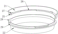
Preferably, the tapered sleeve assembly comprises: the device comprises a conical sleeve I21, a conical sleeve II 22, a conical sleeve III 23 and a conical sleeve IV 24; the tapered sleeve I21, the tapered sleeve II 22, the tapered sleeve III 23 and the tapered sleeve IV 24 are sequentially connected, a closing-up step 25 with a convex radial length is inwards arranged at the circumference of the end part of the small caliber on the tapered sleeve I21, a plurality of locking boss abdicating grooves 26 are uniformly arranged on the closing-up step 25 towards the inner wall of the tapered sleeve I21 at equal angles, and the parts of the closing-up step 25, which are positioned in the non-locking boss abdicating groove 26, are uniformly provided with stop blocks 27 with the same number as the locking boss abdicating grooves 26;
the conical sleeve II 22 is uniformly provided with a plurality of locking bosses 28 protruding outwards in the radial direction in the circumferential direction at the end part with the large diameter of the conical sleeve II 22, the outer wall of the conical sleeve II 22, which is positioned at the lower part of the locking bosses 28, is provided with circumferential bosses 29 protruding outwards in the radial direction, and the number of the locking bosses 28 is equal to that of the locking boss abdicating grooves 26, and the number of the locking bosses is three.
All articulated in 2 upper ends of coexistence post with high position have axis of rotation I3, fixedly connected with toper cover I21's outer wall between two axis of rotation I3, axis of rotation I3 rotates and can drives toper cover I21 and rotate in step. The conical sleeve I21 is a conical sleeve with a certain taper, and two ends of the conical sleeve are open. The port of the end with the smaller outer diameter of the conical sleeve I21 can be sleeved with the port of the clamping fixed conical sleeve II 22, and the circumference of the port corresponding to the conical sleeve I21 is inwards provided with a closing-up step 25 with a certain radial length and a bulge.
Three groups of locking bosses 28 which are protruded outwards along the radial direction are uniformly and integrally fixed with the outer wall at the port of the conical sleeve II 22 which is clamped and fixed with the conical sleeve I21 at a certain equal angle. The closing-up step 25 evenly distributes from the equal angle of inner wall department circumference and has a plurality of locking boss groove of stepping down 26, and this technical scheme design is three groups, and locking boss groove of stepping down 26 has certain width, and every locking boss groove of stepping down 26 is fixed with the block piece 27 that has certain protruding height with revolving to the closing-up step 25 up end of certain circumference angle department of biasing.
Preferably, the length of the locking boss 28 extending outwards in the radial direction is smaller than the depth of the locking boss abdicating groove 26, the circumferential arc length of the locking boss 28 is smaller than the circumferential arc length of the locking boss abdicating groove 26, and the axial distance between the circumferential boss 29 and the locking boss 28 is equal to the thickness of the closing-up step 25 on the conical sleeve I21.
The locking boss 28 extends radially outward a length less than the depth of the locking boss relief groove 26. And the circumferential arc length of each group of locking bosses 28 is smaller than that of the locking boss abdicating groove 26, so that when the conical sleeve II 22 is sleeved with the conical sleeve I21, the locking bosses 28 of the conical sleeve II 22 can penetrate through the locking boss abdicating grooves 26 in the port of the conical sleeve I21. A circumferential convex circumferential boss 29 is integrally fixed on the outer wall of the conical sleeve II 22 axially below the locking boss 28, and the axial distance between the circumferential boss 29 and the locking boss 28 is equal to the thickness of the closing-in step 25 on the conical sleeve I21.
When the taper sleeve II 22 and the taper sleeve I21 are fixedly connected in a sleeved clamping manner, the locking boss 28 penetrates through the locking boss abdicating groove 26 and then rotates the taper sleeve II 22, the taper sleeve II 22 rotates relative to the taper sleeve I21, the locking boss 28 and the circumferential boss 29 below the locking boss 28 clamp the closing-in step 25 of the taper sleeve I21, the taper sleeve II 22 is fixed to the taper sleeve I21 in a clamped manner, and the stop block 27 on the closing-in step 25 is used for limiting the locking boss 28 of the taper sleeve II 22 in a rotating angle manner.
Preferably, the conical sleeve II 22, the conical sleeve III 23 and the conical sleeve IV 24 are sleeved in sequence in a telescopic characteristic.
Conical sleeve II 22, conical sleeve III 23, conical sleeve IV 24 are the conical sleeve that has certain tapering, and all be that the upper end port external diameter is greater than lower extreme port external diameter, conical sleeve II 22, conical sleeve III 23, conical sleeve IV 24 from last cup joints down in proper order, because conical structural relation makes the conical combination cover that above-mentioned three conical sleeve is constituteed have flexible characteristic, make conical sleeve II 22 dismantle the back from conical sleeve I21, conical sleeve II 22, conical sleeve III 23, conical sleeve IV 24 can shrink and place, avoid occupying too much storing space.
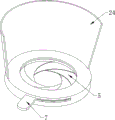
Preferably, semi-spherical convex shift points 30 are uniformly arranged on one side end surface of the rotating groove 12 at equal angles, and semi-spherical concave shift point grooves matched with the shift points 30 in shape are arranged on the corresponding side end surface of the rotating valve 7.
The rotation groove 12 of the clamping plate shell 4 has a certain angle limiting effect on the rotation flap 7 of the rotary disc 6, hemispherical convex gear clamping points 30 are uniformly fixed on one side end face of the rotation groove 12 at equal angles, and hemispherical concave clamping point grooves (not shown) matched with the hemispherical convex clamping points are arranged on the corresponding side end face of the rotation flap 7. When rotating lamella 7 and rotating groove 12 inside one side and rotating to the opposite side, the fender position stuck point 30 of different angles can rotate different fender position to rotating lamella 7 and carry out the screens fixed, and each keeps off position stuck point 30 and all can be fixed the screens of rotating lamella 7 to be used for carrying out the screens fixed to the radial length that screens 5 spiral extension is different to the screens, be convenient for carry out the locking screens of neck to the poultry of different sizes and fix. When the rotating flap 7 is shifted to the initial end, the rotary disc 6 drives the clamping plate 5 to be folded into the clamping plate groove 8, the middle circular hollow area of the clamping plate shell 4 cannot be extended out, and the poultry neck can freely penetrate through the clamping plate groove. When the rotating valve 7 is shifted to the other end of the rotating groove 12, the rotating disc 6 drives the clamping plate 5 to rotate, the maximum spiral radial extension length of the radial length of the circular hollow area is achieved, and the periphery of the neck of the poultry can be locked, clamped and fixed in the state.
Preferably, the base 1 is a frame structure shaped like a Chinese character ri, and the two sides of the upright post 2 and the base 1 are fixedly connected with obliquely distributed support rods 31.
The device is mainly used for inverting and fixing the poultry so as to carry out hypodermic injection or intramuscular injection at the claw position of the neck of the poultry. The lower part of the device is a base 1, the base 1 is of a frame structure shaped like a Chinese character ri, vertical upright posts 2 are fixedly connected to the middle positions of two long edges of the base 1 respectively, and supporting rods 31 which are obliquely distributed are fixedly connected to the two sides of each upright post 2 and the base 1.
Preferably, the clamping plate 5 is arc-shaped, the width of the clamping plate 5 is equal to the width of the clamping plate groove 8, and the number of the clamping plates 5 is six.
A rotary locking clamping structure is fixed at the lower end of the conical sleeve IV 24. The lower end port of the conical sleeve IV 24 is fixedly connected with a clamping plate shell 4, the clamping plate shell 4 is integrally a circular ring-shaped sleeve with a certain annular wall thickness, and the middle part of the clamping plate shell is a larger circular hollow penetrating area. The inside circular arc wall of screens board shell 4 is inwards opened has the screens board groove 8 of certain degree of depth and certain width, is provided with a plurality of screens boards 5 (this device is provided with six screens boards 5) in screens board inslot 8 inside, and six screens boards 5 are the circumference evenly distributed articulated in screens board groove 8. The whole screens board 5 is arc, and the width keeps unanimous and thickness is thinner with screens board groove 8 width, and an up end at the both ends of screens board 5 is provided with uide pin 9, and a lower terminal surface is provided with rotating pin 10, and six screens boards 5 are adjacent end to end and stack in proper order around the circumference in screens board groove 8, and one of them screens board 5 overlaps and stacks certain region in every two adjacent screens boards 5 below the uide pin 9 of last screens board 5. The rotating pins 10 on the lower end surfaces of the front ends of the six clamping plates 5 are hinged with the lower ends of the clamping plate grooves 8.
Preferably, the width of the guide pin slot 11 is equal to the outer diameter of the guide pin 9.
A rotary table 6 is arranged between the interlayers of the upper end surfaces of the six clamping plates 5 and the upper end surfaces of the clamping plate grooves 8, guide pin grooves 11 with the radial trend are arranged on the rotary table 6 at the positions corresponding to the guide pins 9 on the upper end surfaces of the clamping plates 5, and the width of each guide pin groove 11 is matched with the outer diameter of each guide pin 9, so that the guide pins 9 can be just placed in the guide pin grooves 11. And the guide pin groove 11 has a certain length in the radial direction so that the guide pin 9 can slide inside the guide pin groove 11. One side of the outer end of the rotary disc 6 is integrally provided with a rotary flap 7 extending outwards, the outer wall of the clamping plate shell 4 corresponding to the rotary flap 7 is provided with a rotary groove 12 with a certain arc length, and the radian of the rotary groove 12 can enable the rotary flap 7 to drive the rotary disc 6 to rotate by a certain angle. And because the rotating pin 10 at the lower end of the clamping plate 5 is hinged on the clamping plate shell 4, and the guide pin 9 at the upper end can slide along the radial direction in the guide pin groove 11 of the rotary disc 6, when the rotary disc 6 rotates, the clamping plate 5 can be driven to rotate towards the axle center direction, and when the six clamping plates 5 simultaneously rotate towards the axle center direction synchronously, the six clamping plates can play a role of spirally extending from the edge to the center on the middle circular hollow part of the clamping plate shell 4, so that the clamping plates are used for locking, clamping and fixing the periphery of the neck of the poultry.
Preferably, the external thread section 20 is a fine thread.
A rotation locking structure is fixed on one rotation shaft I3 in rotation shafts I3 fixed on two sides of a conical sleeve I21, a rotation shaft II 13 is coaxially and fixedly connected to the rotation shaft I3 on the side, the outer diameter of the rotation shaft II 13 is smaller than that of the rotation shaft I3, a guide groove 19 with a certain length is formed in the position, on the outer end face of the rotation shaft II 13, of the circumferential outer wall on one side, facing inwards in the axial direction, of the circumferential outer wall, an outer threaded section 20 with a certain axial length is designed on the circumferential outer wall, facing inwards, of the outer end face of the rotation shaft II 13, the outer threaded section 20 is a fine thread, and the axial length of the outer threaded section 20 is smaller than that of. A fixed ratchet disc 14 is integrally fixed on the peripheral circumferential region of the rotating shaft II 13 on the outer end face of the upright post 2, the end face of each ratchet of the fixed ratchet disc 14 faces outwards, and the ratchets face to one side. The movable ratchet plate 15 is sleeved on the second rotating shaft 13, the ratchet disc surface of the movable ratchet plate 15 faces the inner side and can be meshed with the ratchets of the fixed ratchet plate 14, a circumferential side surface of the rear end face of the movable ratchet plate 15 is fixedly provided with a circumferential convex handheld boss 16, the handheld convex strip can be conveniently and manually operated by an operator to move axially, and an inner hole of the movable ratchet plate 15 is fixedly provided with a guide block (not shown in the figure) arranged in the guide groove 19 and used for ensuring that the movable ratchet plate 15 can always keep synchronous rotation with the second rotating shaft 13.
A locking nut 17 is in threaded sleeve joint with the external threaded section 20 on the rear side of the movable ratchet plate 15, and internal threads are arranged on the inner wall of an inner hole of the locking nut 17 and are in threaded sleeve joint with the external threaded section 20 of the rotating shaft II 13. The cover has spring 18 on axis of rotation II 13 between activity ratchet dish 15 and lock nut 17, spring 18 both ends are connected with activity ratchet dish 15 and lock nut 17 respectively, and spring 18 is in compression state, the spring 18 top support activity ratchet dish 15 of compression state for the ratchet of the fixed ratchet dish 14 of ratchet interlock of activity ratchet dish 15, fixed ratchet dish 14 screens fixed to activity ratchet dish 15 promptly this moment, thereby make axis of rotation II 13 and axis of rotation I3 drive taper sleeve I21 and can not take place to rotate, make taper sleeve I21 be in fixed state. When the taper sleeve I21 needs to be turned over for a certain angle and then kept fixed, the handheld boss 16 is controlled to axially pull the movable ratchet plate 15 outwards, at the moment, the ratchets of the movable ratchet plate 15 are separated from the fixed ratchet plate 14, then the movable ratchet plate 15 is rotated to a proper angle, then the movable ratchet plate 15 moves inwards along the axial direction under the propping action of the spring 18, and the fixed ratchet plate 14 is meshed again, so that the turning back angle of the taper sleeve I21 is kept fixed.
When the poultry needs to be injected subcutaneously at the neck position or intramuscularly at the claw position, the tapered sleeves in the initial state of the device are in a vertical state after being combined, and simultaneously, the clamping plates 5 are all accommodated in the clamping plate grooves 8 of the clamping plate shell 4. Invert the poultry from the port of toper cover I21 and go into in, the head of poultry can stretch out from the centre round hole department of screens board shell 4 under the action of gravity, stir and rotate lamella 7 and rotate to suitable angle in rotating 12 insides of groove, carousel 6 drives screens 5 spirals and radially stretches out inwards and fix the screens to poultry neck locking, and the poultry is fixed the completion this moment. The rotation locking structure is controlled to enable the conical sleeve combination to rotate to a proper angle and then be fixed, so that the optimal overturning angle can be selected for injecting the poultry.
The utility model discloses an innovation technical point and beneficial effect lie in at least:
1. this device is directed against the poultry at the characteristics of injection neck and claw, and the pertinence adopts the taper sleeve to invert and places the poultry and make the claw and the head of poultry expose, inverts inside the taper sleeve and can carry out the oppression formula through the taper sleeve of going up thick thin down to the characteristics of poultry size and tighten fixedly, simple structure convenience, effect are stable.
2. Correspond poultry head position and be provided with rotatory locking screens structure and stir 7 unified control screens boards 5 and reach the fixed effect of poultry neck locking screens to the regional enlargements and the shrink of middle passageway for the poultry neck can't swing head when injecting, is used for guaranteeing the stability and the success rate of injection, very big improvement efficiency. The head of the poultry is fixed without adding hands. Simultaneously this rotational locking screens structure easy operation, all screens board 5 homoenergetic guarantee to receive and release in unison, and 360 degrees locks simultaneously in neck periphery, guarantees fixed stability. Meanwhile, different gears are designed when the poultry neck is folded and unfolded, so that the poultry neck locking device can achieve locking effects on poultry necks of different body types, and has strong universality.
3. This device can control the holistic angle of poultry through rotating locking structure, can reach the effect of real-time auto-lock after angular adjustment, has guaranteed that the poultry can inject through the best angle, and the adjustment is convenient, and is fixed stable. The poultry can be injected by adopting a normal and comfortable standing posture without stooping down or tilting the head of an operator, so that the labor consumption of the operator is reduced, and the injection efficiency is further improved.
4. Adopt between toper cover I21 and the toper cover II 22 to cup joint and rotate the fixed mode of screens, make it have the detachable characteristic, can conveniently dismantle the washing clearance until storing. And meanwhile, the conical sleeves II 22-IV are sequentially sleeved from top to bottom, and the conical combined sleeve formed by the three conical sleeves has a telescopic characteristic due to the conical structural relationship, so that after the conical sleeve II 22 is disassembled from the conical sleeve I21, the conical sleeve II 22, the conical sleeve III 23 and the conical sleeve IV 24 can be contracted and placed, and the phenomenon that too much storage space is occupied is avoided.
The foregoing is only a preferred embodiment of the present invention, and it should be noted that, for those skilled in the art, a plurality of modifications and decorations can be made without departing from the principle of the present invention, and these modifications and decorations should also be regarded as the protection scope of the present invention.