CN213195670U - Waste material clearing device of numerical control vertical lathe - Google Patents
Waste material clearing device of numerical control vertical lathe Download PDFInfo
- Publication number
- CN213195670U CN213195670U CN202022056894.XU CN202022056894U CN213195670U CN 213195670 U CN213195670 U CN 213195670U CN 202022056894 U CN202022056894 U CN 202022056894U CN 213195670 U CN213195670 U CN 213195670U
- Authority
- CN
- China
- Prior art keywords
- fixedly connected
- lead screw
- movable block
- vertical lathe
- workbench
- Prior art date
- Legal status (The legal status is an assumption and is not a legal conclusion. Google has not performed a legal analysis and makes no representation as to the accuracy of the status listed.)
- Active
Links
Images


Abstract
The utility model discloses a waste material clearing device of numerical control vertical lathe, comprises a workbench, a plurality of supporting legs of bottom fixedly connected with of workstation, the top of workstation is equipped with the push pedal, the equal fixedly connected with connecting block in both ends of push pedal, the below of workstation is equipped with the movable block, the equal fixedly connected with connecting plate in both sides of movable block, two spouts have been seted up to the bottom of workstation, be equipped with the slider in the spout, the bottom of slider and the top fixed connection of connecting plate, the first lead screw of top fixedly connected with of connecting plate. A numerical control vertical lathe's waste material clearing device, belong to numerical control vertical lathe technical field, only need a motor drive second lead screw to rotate, can make push pedal round trip movement, and then make the waste material slide in the collecting box through the rectangle relief hole, make things convenient for in-service use, ensure simultaneously that the push pedal contacts with the top of workstation all the time.
Description
Technical Field
The utility model relates to a numerical control vertical lathe technical field, in particular to numerical control vertical lathe's waste material clearing device.
Background
The numerical control lathe and the turning center are high-precision and high-efficiency automatic machine tools. The multi-station tool turret or the power tool turret is equipped, so that the machine tool has wide processing technological performance, can process complex workpieces such as linear cylinders, oblique line cylinders, circular arcs and various threads, grooves, worms and the like, has various compensation functions of linear interpolation and circular arc interpolation, and plays a good economic effect in the batch production of complex parts. Adding man-hour to the part, the workstation can produce the waste material, and the waste material is iron fillings mostly, when carrying out artifical the cleaing away, pricks the hand easily, and is inconvenient to clean, however, finds through the retrieval, has disclosed a numerical control vertical lathe waste material clearing device in the chinese patent that the publication number is CN207656353U authorizes, needs two motors to drive two threaded rods synchronous rotation simultaneously, and the motor quantity that sets up is more, and manufacturing and use cost are higher.
SUMMERY OF THE UTILITY MODEL
A primary object of the present invention is to provide a waste removing device for a numerically controlled vertical lathe, which can effectively solve the problems of the prior art.
In order to achieve the above purpose, the utility model adopts the following technical scheme:
a waste removing device of a numerical control vertical lathe comprises a workbench, wherein a plurality of supporting legs are fixedly connected to the bottom of the workbench, a push plate is arranged at the top of the workbench, connecting blocks are fixedly connected to two ends of the push plate, a movable block is arranged below the workbench, connecting plates are fixedly connected to two sides of the movable block, two sliding grooves are formed in the bottom of the workbench, sliding blocks are arranged in the sliding grooves, the bottom of each sliding block is fixedly connected with the top of the corresponding connecting plate, a first lead screw is fixedly connected to the top of each connecting plate, a through hole is formed in the top of each connecting block and penetrates through the through hole, nuts positioned at the tops of the connecting blocks are sleeved on the outer portions of the first lead screws, fixing plates are symmetrically arranged on two sides of each movable block, the tops of the fixing plates are fixedly connected with the bottom of the workbench, and a supporting plate is fixedly, two rectangle relief holes have been seted up to the top symmetry of workstation, the slope of rectangle relief hole sets up, the top of backup pad is equipped with the collecting box with rectangle relief hole matched with, two be equipped with between the fixed plate with movable block matched with drive assembly.
Preferably, the driving assembly comprises a second lead screw arranged between the two fixing plates, the second lead screw penetrates through the movable block, the second lead screw is in threaded connection with the movable block, one end of the second lead screw is connected with one of the fixing plates through a bearing, and the other end of the second lead screw is connected with the other fixing plate through a motor.
Preferably, the cross sections of the sliding groove and the sliding block are both T-shaped structures.
Preferably, the bottoms of the supporting legs are fixedly connected with non-slip mats.
Preferably, a handle is fixedly connected to one side of the nut.
Compared with the prior art, the utility model discloses following beneficial effect has: through setting up the workstation, the supporting leg, the push pedal, the connecting block, the movable block, the connecting plate, first lead screw, the nut, the spout, the slider, the fixed plate, the backup pad, the rectangle relief hole, collecting box and drive assembly's cooperation, only need a motor drive second lead screw to rotate, can make the push pedal round trip movement, and then make the waste material slide in the collecting box through the rectangle relief hole, it is low to make things convenient for practical use, ensure simultaneously that the push pedal contacts with the top of workstation all the time, through the slipmat that sets up, reduce the gliding possibility of the relative ground of supporting leg, through the handle that sets up, be convenient for drive nut rotates.
Drawings
Fig. 1 is a schematic view of the overall structure of a waste removing device of a numerical control vertical lathe according to the present invention;
fig. 2 is a schematic side view of the waste removing device of the numerical control vertical lathe of the present invention;
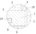
fig. 3 is a partially enlarged schematic view of a portion a of fig. 1.
In the figure: 1. a work table; 2. supporting legs; 3. pushing the plate; 4. connecting blocks; 5. a movable block; 6. a connecting plate; 7. a first lead screw; 8. a nut; 9. a chute; 10. a slider; 11. a fixing plate; 12. a support plate; 13. a rectangular discharge hole; 14. a collection box; 15. a second lead screw; 16. a bearing; 17. a motor; 18. a non-slip mat; 19. a through hole; 20. a handle.
Detailed Description
In order to make the technical means, creation features, achievement purposes and functions of the present invention easy to understand, the present invention is further described below with reference to the following embodiments.
In the description of the present invention, it should be noted that the terms "upper", "lower", "inner", "outer", "front end", "rear end", "both ends", "one end", "the other end" and the like indicate orientations or positional relationships based on the orientations or positional relationships shown in the drawings, and are only for convenience of description and simplification of description, but do not indicate or imply that the device or element to which the reference is made must have a specific orientation, be constructed in a specific orientation, and be operated, and thus, should not be construed as limiting the present invention. Furthermore, the terms "first" and "second" are used for descriptive purposes only and are not to be construed as indicating or implying relative importance.
In the description of the present invention, it is to be noted that, unless otherwise explicitly specified or limited, the terms "mounted," "disposed," "connected," and the like are to be construed broadly, and for example, "connected" may be either fixedly connected or detachably connected, or integrally connected; can be mechanically or electrically connected; they may be connected directly or indirectly through intervening media, or they may be interconnected between two elements. The specific meaning of the above terms in the present invention can be understood in specific cases to those skilled in the art.
As shown in figures 1-3, a waste removing device of a numerical control vertical lathe comprises a workbench 1, the bottom of the workbench 1 is fixedly connected with a plurality of supporting legs 2, the top of the workbench 1 is provided with a push plate 3, both ends of the push plate 3 are fixedly connected with connecting blocks 4, a movable block 5 is arranged below the workbench 1, both sides of the movable block 5 are fixedly connected with connecting plates 6, the bottom of the workbench 1 is provided with two chutes 9, the chutes 9 are internally provided with sliders 10, the bottoms of the sliders 10 are fixedly connected with the tops of the connecting plates 6, the top of the connecting plate 6 is fixedly connected with a first lead screw 7, the top of the connecting block 4 is provided with a through hole 19, the first lead screw 7 penetrates through the through hole 19, the outer part of the first lead screw 7 is sleeved with a nut 8 positioned at the top of the connecting block 4, both sides of the movable block 5 are symmetrically provided with fixing, the side, far away from each other, of each of the two fixed plates 11 is fixedly connected with a supporting plate 12, the top of the workbench 1 is symmetrically provided with two rectangular discharge holes 13, the rectangular discharge holes 13 are obliquely arranged, the top of each supporting plate 12 is provided with a collecting box 14 matched with the rectangular discharge holes 13, and a driving assembly matched with the movable block 5 is arranged between the two fixed plates 11;
in this embodiment, the driving assembly includes a second lead screw 15 disposed between the two fixing plates 11, the second lead screw 15 penetrates through the movable block 5, the second lead screw 15 is connected to the movable block 5 in a threaded manner, one end of the second lead screw 15 is connected to one of the fixing plates 11 through a bearing 16, and the other end of the second lead screw 15 is connected to the other fixing plate 11 through a motor 17.
In this embodiment, the cross sections of the sliding groove 9 and the sliding block 10 are both T-shaped structures, so as to prevent the sliding block 10 from separating from the sliding groove 9.
In the embodiment, the bottom of the supporting leg 2 is fixedly connected with a non-slip mat 18, and the possibility of the supporting leg 2 sliding relative to the ground is reduced by the arranged non-slip mat 18.
In this embodiment, a handle 20 is fixedly connected to one side of the nut 8, and the nut 8 is conveniently driven to rotate by the handle 20.
It should be noted that, the utility model relates to a waste material removing device of a numerical control vertical lathe, when in use, the nut 8 is rotated to make the connecting block 4 contact with the top of the workbench 1, and further make the push plate 3 contact with the top of the workbench 1, the motor 17 drives the second lead screw 15 to rotate, the second lead screw 15 drives the movable block 5 to move, the sliding chute 9 and the sliding block 10 are matched to make the connecting plate 6 stably move, and further make the movable block 5 stably move, the connecting plate 6 drives the first lead screw 7 to move, and further make the push plate 3 move at the top of the workbench 1, the motor 17 drives the second lead screw 15 to periodically rotate forward and backward, and further make the push plate 3 move back and forth at the top of the workbench 1, only one motor 17 is needed to drive the second lead screw 15 to rotate, and then the push plate 3 can move back and forth, and further make waste material slide into the collecting box 14 through the rectangular discharge hole, the manufacturing and using cost is low, the practical use is convenient, the possibility of sliding of the supporting leg 2 relative to the ground is reduced through the arranged non-slip mat 18, and the nut 8 is convenient to drive to rotate through the arranged handle 20.
The basic principles and the main features of the invention and the advantages of the invention have been shown and described above. It will be understood by those skilled in the art that the present invention is not limited to the above embodiments, and that the foregoing embodiments and descriptions are provided only to illustrate the principles of the present invention without departing from the spirit and scope of the present invention. The scope of the invention is defined by the appended claims and equivalents thereof.
Claims (5)
1. The utility model provides a waste material clearing device of numerical control vertical lathe which characterized in that: comprises a workbench (1), wherein the bottom of the workbench (1) is fixedly connected with a plurality of supporting legs (2), the top of the workbench (1) is provided with a push plate (3), the two ends of the push plate (3) are fixedly connected with connecting blocks (4), a movable block (5) is arranged below the workbench (1), the two sides of the movable block (5) are fixedly connected with connecting plates (6), the bottom of the workbench (1) is provided with two sliding grooves (9), the sliding grooves (9) are internally provided with sliding blocks (10), the bottom of the sliding blocks (10) is fixedly connected with the top of the connecting plates (6), the top of the connecting plates (6) is fixedly connected with a first lead screw (7), the top of the connecting blocks (4) is provided with a through hole (19), the first lead screw (7) penetrates through the through hole (19), the outer sleeve of the first lead screw (7) is provided with a nut (8) positioned at the top of the connecting, the bilateral symmetry of movable block (5) is equipped with fixed plate (11), the top of fixed plate (11) and the bottom fixed connection of workstation (1), two the equal fixedly connected with backup pad (12) in one side that fixed plate (11) kept away from mutually, two rectangle relief hole (13) have been seted up to the top symmetry of workstation (1), rectangle relief hole (13) slope sets up, the top of backup pad (12) is equipped with collecting box (14) with rectangle relief hole (13) matched with, two be equipped with between fixed plate (11) with movable block (5) matched with drive assembly.
2. The scrap removal apparatus for a numerically controlled vertical lathe according to claim 1, wherein: the driving assembly comprises a second lead screw (15) arranged between two fixing plates (11), the second lead screw (15) penetrates through the movable block (5), the second lead screw (15) is in threaded connection with the movable block (5), one end of the second lead screw (15) is connected with one of the fixing plates (11) through a bearing (16), and the other end of the second lead screw (15) is connected with the other fixing plate (11) through a motor (17).
3. The scrap removal apparatus for a numerically controlled vertical lathe according to claim 1, wherein: the cross sections of the sliding groove (9) and the sliding block (10) are both T-shaped structures.
4. The scrap removal apparatus for a numerically controlled vertical lathe according to claim 1, wherein: the bottom of the supporting leg (2) is fixedly connected with an anti-skid pad (18).
5. The scrap removal apparatus for a numerically controlled vertical lathe according to claim 1, wherein: and one side of the nut (8) is fixedly connected with a handle (20).
Priority Applications (1)
| Application Number | Priority Date | Filing Date | Title |
|---|---|---|---|
| CN202022056894.XU CN213195670U (en) | 2020-09-18 | 2020-09-18 | Waste material clearing device of numerical control vertical lathe |
Applications Claiming Priority (1)
| Application Number | Priority Date | Filing Date | Title |
|---|---|---|---|
| CN202022056894.XU CN213195670U (en) | 2020-09-18 | 2020-09-18 | Waste material clearing device of numerical control vertical lathe |
Publications (1)
| Publication Number | Publication Date |
|---|---|
| CN213195670U true CN213195670U (en) | 2021-05-14 |
Family
ID=75822972
Family Applications (1)
| Application Number | Title | Priority Date | Filing Date |
|---|---|---|---|
| CN202022056894.XU Active CN213195670U (en) | 2020-09-18 | 2020-09-18 | Waste material clearing device of numerical control vertical lathe |
Country Status (1)
| Country | Link |
|---|---|
| CN (1) | CN213195670U (en) |
Cited By (1)
| Publication number | Priority date | Publication date | Assignee | Title |
|---|---|---|---|---|
| CN114147301A (en) * | 2021-11-08 | 2022-03-08 | 深圳市高士达精密机械有限公司 | Tapping machine |
-
2020
- 2020-09-18 CN CN202022056894.XU patent/CN213195670U/en active Active
Cited By (1)
| Publication number | Priority date | Publication date | Assignee | Title |
|---|---|---|---|---|
| CN114147301A (en) * | 2021-11-08 | 2022-03-08 | 深圳市高士达精密机械有限公司 | Tapping machine |
Similar Documents
| Publication | Publication Date | Title |
|---|---|---|
| CN107322096A (en) | A kind of adjustable bead cutter | |
| CN211305810U (en) | Steel pipe off-line inner burr grinding machine | |
| CN210209386U (en) | Multifunctional pipe cutting chamfering machine | |
| CN213195670U (en) | Waste material clearing device of numerical control vertical lathe | |
| CN110605411A (en) | Scrap cleaning equipment for hardware machining | |
| CN209935486U (en) | Stone material processing waste material recovery unit | |
| CN218362539U (en) | Automatic nut tapping machine | |
| CN212681991U (en) | Working table for collecting machining scraps of mechanical parts | |
| CN214185558U (en) | Scrap recovery device of interrupted saw | |
| CN212421203U (en) | Workpiece turnover device for machining | |
| CN211163371U (en) | Mechanical automatic grinding device for workpiece | |
| CN210306725U (en) | Workbench for vertical machine tool | |
| CN209919413U (en) | Automatic feeding device for metal workpieces | |
| CN210849389U (en) | Machine tool with cooling and recycling functions | |
| CN212043786U (en) | Table board cleaning device of numerical control machining center | |
| CN219665729U (en) | Operating table of machining center | |
| CN218533538U (en) | Planer-type milling machine workstation is used in lathe bed processing convenient to it is clean | |
| CN217750373U (en) | Two-end machining table | |
| CN217860268U (en) | Lathe with piece clearance structure | |
| CN212683448U (en) | Polishing device capable of rapidly switching clamps for machining hardware non-standard parts | |
| CN215147458U (en) | Bearing grinds processing and uses automatic lathe | |
| CN218362543U (en) | Automatic tapping equipment for nut blank | |
| CN217493724U (en) | Burr polishing equipment for plastic part production | |
| CN214921925U (en) | Frock clamp for welding | |
| CN218695961U (en) | Numerical control milling machine |
Legal Events
| Date | Code | Title | Description |
|---|---|---|---|
| GR01 | Patent grant | ||
| GR01 | Patent grant |