CN213131194U - Uropoiesis surgery nursing washing unit - Google Patents
Uropoiesis surgery nursing washing unit Download PDFInfo
- Publication number
- CN213131194U CN213131194U CN202020610705.6U CN202020610705U CN213131194U CN 213131194 U CN213131194 U CN 213131194U CN 202020610705 U CN202020610705 U CN 202020610705U CN 213131194 U CN213131194 U CN 213131194U
- Authority
- CN
- China
- Prior art keywords
- vertical cylinder
- waste liquid
- cleaning
- cavity
- guide plate
- Prior art date
- Legal status (The legal status is an assumption and is not a legal conclusion. Google has not performed a legal analysis and makes no representation as to the accuracy of the status listed.)
- Active
Links
Images


Landscapes
- External Artificial Organs (AREA)
Abstract
The utility model provides an urinary surgery nursing flushing device, which comprises a vertical cylinder, wherein the upper end of the vertical cylinder is open, the lower end of the vertical cylinder is closed, the upper end of the vertical cylinder is provided with an annular seat plate, a circular flushing hole is arranged in the middle of the annular seat plate, the vertical cylinder is provided with a supporting plate, an annular seat is fixed in the middle of the supporting plate, a plurality of cleaning pipes are vertically penetrated and fixed on the annular seat, the top ends of the cleaning pipes are provided with cleaning holes, and the lower ends of the cleaning pipes are jointly fixed with a total; a plurality of water outlet holes are formed in the supporting plate; a water guide plate is fixed in the vertical cylinder below the total water inlet cavity, a waste liquid collecting cavity and a cleaning liquid storage cavity are arranged in the vertical cylinder below the water guide plate, a through hole is formed in one side of the water guide plate, and the lower end of the through hole is communicated with a liquid outlet pipe; the utility model discloses simple structure, when washing device washed uropoiesis surgery patient focus position, it is convenient to wash, and the patient travelling comfort is strong when washing.
Description
Technical Field
The utility model relates to the technical field of medical equipment, concretely relates to uropoiesis surgery nursing washing unit.
Background
The main therapeutic range of urology surgery is: various urinary stones and complex kidney stones; kidney and bladder tumors; prostatic hyperplasia and prostatitis; inflammation and tumor of the testicle epididymis; hydrocele of tunica vaginalis of testis; various urinary system injuries; congenital malformations of the urinary system such as hypospadias, cryptorchidis, hydronephrosis caused by stenosis of the ureteropelvic junction, etc.
At present, in the nursing work after the urinary surgery, the focus part needs to be washed regularly, but at present, hospitals generally have no better special equipment, and the patient needs to keep the leg clenching and lying posture during the washing, which is very uncomfortable, and the patient is difficult to persist for a long time, so the washing is very troublesome.
SUMMERY OF THE UTILITY MODEL
The utility model provides an uropoiesis surgery nursing washing unit, simple structure, when washing unit washed uropoiesis surgery patient's focus position, it was convenient to wash, and the patient travelling comfort is strong when washing.
In order to achieve the above object, the utility model provides a following technical scheme:
an urological nursing flushing device comprises a vertical cylinder, wherein the upper end of the vertical cylinder is open, the lower end of the vertical cylinder is closed, an annular seat plate is arranged at the upper end of the vertical cylinder, a circular flushing hole is formed in the middle of the annular seat plate, a supporting plate is arranged on the vertical cylinder, an annular seat is fixed in the middle of the supporting plate, a plurality of cleaning pipes vertically penetrate through the annular seat and are fixed, cleaning holes are formed in the top ends of the cleaning pipes, and a total water inlet cavity is jointly fixed at the lower ends of the cleaning pipes; a plurality of water outlet holes are formed in the supporting plate; a water guide plate is fixed in the vertical cylinder below the total water inlet cavity, a waste liquid collecting cavity and a cleaning liquid storage cavity are arranged in the vertical cylinder below the water guide plate, and a waste liquid collecting cavity door and a cleaning liquid storage cavity door are arranged on the side wall of the vertical cylinder corresponding to the waste liquid collecting cavity and the cleaning liquid storage cavity; a cleaning solution storage tank and a water pump are placed in the cleaning solution storage cavity, the bottom end of the cleaning solution storage tank is connected with the liquid inlet end of the water pump through a first pipeline, the liquid outlet end of the water pump is communicated with the main water inlet cavity through a second pipeline, and the second pipeline penetrates through the water guide plate and is fixedly connected with the water guide plate in a sealing mode; the through-hole has been seted up to water deflector one side, and through-hole lower extreme intercommunication has the drain pipe, the waste liquid collecting tank has been placed to the waste liquid collecting cavity, the drain pipe is located the feed liquor end top of waste liquid collecting tank.
Furthermore, the front end, the rear end, the left end and the right end of the vertical cylinder are respectively provided with a braking roller.
Furthermore, at least 5 cleaning holes are formed in the middle of the top of the cleaning pipe.
Furthermore, handrails are fixed on the left side and the right side of the vertical cylinder.
Further, the waste liquid collecting tank includes the waste liquid collecting tank body, waste liquid collecting tank lid, feed liquor funnel, threaded connection has the waste liquid collecting tank lid on the waste liquid collecting tank body, the last fixed intercommunication of waste liquid collecting tank lid has the feed liquor funnel, the drain pipe is located feed liquor funnel top.
Further, the upper end intercommunication of washing liquid holding vessel has into the pipe, and the lower extreme intercommunication has the exit tube, advance all to install the valve on pipe, the exit tube, and all install hose nipple in the end.
The utility model has the advantages that: the utility model discloses uropoiesis surgical nursing washing unit when the patient washs, directly sits on annular bedplate, makes the focus position aim at the scavenge pipe. The washing liquid is derived from the cleaning hole of scavenge pipe, and the washing liquid washes the focus position, washes back waste liquid and derives from the apopore, then in leading-in drain pipe through the water guide plate to collect through the waste liquid collecting tank. The utility model discloses simple structure, when washing device washed uropoiesis surgery patient focus position, it is convenient to wash, and the patient travelling comfort is strong when washing.
Drawings
In order to more clearly illustrate the embodiments of the present invention or the technical solutions in the prior art, the drawings used in the description of the embodiments or the prior art will be briefly described below, it is obvious that the drawings in the following description are only some embodiments of the present invention, and for those skilled in the art, other drawings can be obtained according to these drawings without creative efforts.
FIG. 1 is a front view of the present invention;
fig. 2 is a top view of the present invention;
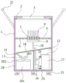
FIG. 3 is a schematic view of the internal structure of the present invention;
FIG. 4 is a top view of the cleaning tube of the present invention;
in the figure: 1. a vertical cylinder; 2. an annular seat plate; 3. flushing the hole; 4. a support plate; 5. an annular seat; 6. cleaning the tube; 7. cleaning the holes; 8. a total water inlet cavity; 9. a water outlet hole; 10. a water guide plate; 11. a waste liquid collection chamber; 12. a cleaning fluid storage chamber; 13. a waste liquid collection chamber door; 14. a cleaning liquid storage chamber door; 15. a cleaning solution storage tank; 16. a water pump; 17. a first pipeline; 18. a second pipeline; 19. a liquid outlet pipe; 20. a waste liquid collection tank; 201. a waste liquid collection tank body; 202. a waste liquid collecting tank cover body; 203. a liquid inlet funnel; 21. a belt brake roller; 22. a grab bar; 23. feeding a pipe; 24. and (4) feeding the pipe.
Detailed Description
In order to make the objects, technical solutions and advantages of the embodiments of the present invention clearer, the embodiments of the present invention will be clearly and completely described below with reference to the accompanying drawings in the embodiments of the present invention, and it is obvious that the described embodiments are some, but not all, embodiments of the present invention. Based on the embodiments in the present invention, all other embodiments obtained by a person skilled in the art without creative efforts belong to the protection scope of the present invention.
As shown in fig. 1-4, a urinary surgery nursing flushing device comprises a vertical cylinder 1, wherein the upper end of the vertical cylinder 1 is open, the lower end of the vertical cylinder is closed, an annular seat plate 2 is arranged at the upper end of the vertical cylinder 1, and a circular flushing hole 3 is formed in the middle of the annular seat plate 2. Vertical section of thick bamboo 1 internal fixation has backup pad 4, is fixed with annular seat 5 in the middle of the backup pad 4, and the vertical penetration is fixed with many scavenge pipes 6 on annular seat 5, and purge orifice 7 has been seted up on the 6 top of scavenge pipe, has seted up 5 at least purge orifices 7 in the middle of the 6 tops of scavenge pipe.
The lower ends of the cleaning pipes 6 are jointly fixed with a main water inlet cavity 8; a plurality of water outlet holes 9 are formed in the supporting plate 4; a water guide plate 10 is fixed in the vertical cylinder 1 below the main water inlet cavity 8, a waste liquid collecting cavity 11 and a cleaning liquid storage cavity 12 are arranged in the vertical cylinder 1 below the water guide plate 10, and a waste liquid collecting cavity door 13 and a cleaning liquid storage cavity door 14 are arranged on the side wall of the vertical cylinder 1 corresponding to the waste liquid collecting cavity 11 and the cleaning liquid storage cavity 12; a cleaning solution storage tank 15 and a water pump 16 are placed in the cleaning solution storage cavity 12, the bottom end of the cleaning solution storage tank 15 is connected with the liquid inlet end of the water pump 16 through a first pipeline 17, the liquid outlet end of the water pump 16 is communicated with the total water inlet cavity 8 through a second pipeline 18, and the second pipeline 18 penetrates through the water guide plate 10 and is fixedly connected with the water guide plate 10 in a sealing mode. The upper end of the cleaning liquid storage tank 15 is communicated with an inlet pipe 23, the lower end is communicated with an outlet pipe 24, valves are respectively arranged on the inlet pipe 23 and the outlet pipe 24, and hose connectors are respectively arranged at the tail ends of the inlet pipe 23 and the outlet pipe 24. By providing the inlet pipe 23 and the outlet pipe 24, the cleaning liquid can be introduced through the inlet pipe 23, and the residual cleaning liquid can be discharged through the outlet pipe 24.
A through hole is formed in one side of the water guide plate 10, the lower end of the through hole is communicated with a liquid outlet pipe 19, a waste liquid collecting tank 20 is placed in the waste liquid collecting cavity 11, and the liquid outlet pipe 19 is located above the liquid inlet end of the waste liquid collecting tank 20. Waste liquid collection tank 20 specifically includes the waste liquid collection tank body 201, waste liquid collection tank lid 202, feed liquor funnel 203, and threaded connection has waste liquid collection tank lid 202 on the waste liquid collection tank body 201, and the last fixed intercommunication of waste liquid collection tank lid 202 has feed liquor funnel 203, and drain pipe 19 is located feed liquor funnel 203 top.
The front, back, left and right ends of the vertical cylinder 1 are respectively provided with a roller 21 with a brake. The roller 21 with the brake facilitates the overall movement of the flushing device. Handrails 22 are fixed on the left side and the right side of the vertical cylinder 1. The handrail can stabilize the body shape of a patient with inconvenient actions and is convenient for the whole pushing of the flushing device.
The utility model discloses uropoiesis surgical nursing washing unit when the patient washs, directly sits on annular bedplate 2, makes the focus position aim at scavenge pipe 6 through flushing hole 3. Then through water pump 16 from washing liquid holding vessel 15 with washing liquid leading-in total intake antrum 8, then the washing liquid is derived from the cleaning hole 7 of scavenge pipe 6, and the washing liquid washes the focus position, and the waste liquid is derived from apopore 9 after washing, then leads into drain pipe 19 through water deflector 10 to collect through waste liquid collecting tank 20, later take out and handle. The utility model discloses simple structure, when washing device washed uropoiesis surgery patient focus position, it is convenient to wash, and the patient travelling comfort is strong when washing.
The above embodiments are only used to illustrate the technical solution of the present invention, and not to limit it; although the present invention has been described in detail with reference to the foregoing embodiments, it should be understood by those skilled in the art that: the technical solutions described in the foregoing embodiments may still be modified, or some technical features may be equivalently replaced; such modifications and substitutions do not depart from the spirit and scope of the present invention in its corresponding aspects.
Claims (6)
1. The urinary surgery nursing flushing device is characterized by comprising a vertical cylinder (1), wherein the upper end of the vertical cylinder (1) is open, the lower end of the vertical cylinder is closed, an annular seat plate (2) is arranged at the upper end of the vertical cylinder (1), a circular flushing hole (3) is formed in the middle of the annular seat plate (2), a support plate (4) is fixed in the vertical cylinder (1), an annular seat (5) is fixed in the middle of the support plate (4), a plurality of cleaning pipes (6) vertically penetrate through the annular seat (5), a cleaning hole (7) is formed in the top end of each cleaning pipe (6), and a total water inlet cavity (8) is jointly fixed at the lower ends of the cleaning pipes (6); a plurality of water outlet holes (9) are formed in the supporting plate (4); a water guide plate (10) is fixed in the vertical cylinder (1) below the total water inlet cavity (8), a waste liquid collecting cavity (11) and a cleaning liquid storage cavity (12) are arranged in the vertical cylinder (1) below the water guide plate (10), and a waste liquid collecting cavity door (13) and a cleaning liquid storage cavity door (14) are installed on the side wall of the vertical cylinder (1) corresponding to the waste liquid collecting cavity (11) and the cleaning liquid storage cavity (12); a cleaning solution storage tank (15) and a water pump (16) are arranged in the cleaning solution storage cavity (12), the bottom end of the cleaning solution storage tank (15) is connected with the liquid inlet end of the water pump (16) through a first pipeline (17), the liquid outlet end of the water pump (16) is communicated with the main water inlet cavity (8) through a second pipeline (18), and the second pipeline (18) penetrates through the water guide plate (10) and is fixedly connected with the water guide plate (10) in a sealing manner; a through hole is formed in one side of the water guide plate (10), the lower end of the through hole is communicated with a liquid outlet pipe (19), a waste liquid collecting tank (20) is placed in the waste liquid collecting cavity (11), and the liquid outlet pipe (19) is located above the liquid inlet end of the waste liquid collecting tank (20).
2. The urological care irrigation device of claim 1, wherein a roller (21) with brake is mounted at each of the front, rear, left and right ends of the vertical tube (1).
3. A uro-surgical nursing irrigation device as in claim 1 characterized in that the top of the washing tube (6) is opened with at least 5 washing holes (7) in the middle.
4. The urological care irrigation device of claim 1, wherein handrails (22) are fixed to the vertical tube (1) on both left and right sides.
5. The urological nursing irrigation device of claim 1, wherein the waste liquid collection tank (20) comprises a waste liquid collection tank (201), a waste liquid collection tank cover (202), and a liquid inlet funnel (203), the waste liquid collection tank cover (202) is connected to the waste liquid collection tank (201) in a threaded manner, the liquid inlet funnel (203) is fixedly communicated with the waste liquid collection tank cover (202), and the liquid outlet pipe (19) is located above the liquid inlet funnel (203).
6. The urological care irrigation device according to claim 1, wherein the cleaning solution storage tank (15) is connected to an inlet pipe (23) at its upper end and to an outlet pipe (24) at its lower end, and wherein the inlet pipe (23) and the outlet pipe (24) are both provided with valves and hose connectors at their ends.
Priority Applications (1)
| Application Number | Priority Date | Filing Date | Title |
|---|---|---|---|
| CN202020610705.6U CN213131194U (en) | 2020-04-22 | 2020-04-22 | Uropoiesis surgery nursing washing unit |
Applications Claiming Priority (1)
| Application Number | Priority Date | Filing Date | Title |
|---|---|---|---|
| CN202020610705.6U CN213131194U (en) | 2020-04-22 | 2020-04-22 | Uropoiesis surgery nursing washing unit |
Publications (1)
| Publication Number | Publication Date |
|---|---|
| CN213131194U true CN213131194U (en) | 2021-05-07 |
Family
ID=75708200
Family Applications (1)
| Application Number | Title | Priority Date | Filing Date |
|---|---|---|---|
| CN202020610705.6U Active CN213131194U (en) | 2020-04-22 | 2020-04-22 | Uropoiesis surgery nursing washing unit |
Country Status (1)
| Country | Link |
|---|---|
| CN (1) | CN213131194U (en) |
-
2020
- 2020-04-22 CN CN202020610705.6U patent/CN213131194U/en active Active
Similar Documents
| Publication | Publication Date | Title |
|---|---|---|
| CN213131194U (en) | Uropoiesis surgery nursing washing unit | |
| CN213724010U (en) | Sitting type constant-temperature and constant-pressure flushing device for urinary surgery | |
| CN211383082U (en) | Uropoiesis surgery washing unit | |
| CN218046010U (en) | Clinical automatic washing unit of uropoiesis surgery | |
| CN215460811U (en) | Type of washing adjustable type traditional chinese medical science gynaecology washes equipment | |
| CN215426500U (en) | Washing unit is used in gynaecology's clinic | |
| CN213157195U (en) | Basis nursing is with splashproof water sick bed device of washing hair | |
| CN211724206U (en) | Gynaecology's sitting posture belt cleaning device that squats with clean and nursing function | |
| CN214259969U (en) | Eye flushing device for femtosecond laser therapy | |
| CN216258534U (en) | Uropoiesis surgical nursing washing unit | |
| CN212369218U (en) | Clinical device of getting of gynaecology and obstetrics | |
| CN214388402U (en) | Uropoiesis is belt cleaning device for surgery | |
| CN206424157U (en) | A kind of CT Room radiography special-purpose vehicle irrigator for urological surgery | |
| CN219481087U (en) | Clinical washing unit that uses | |
| CN220938530U (en) | Anorectal department perineum nursing device | |
| CN215386451U (en) | Anus flusher | |
| CN215134594U (en) | Urinary surgery is clinical with washing unit | |
| CN213491028U (en) | Anus enterochirurgia belt cleaning device | |
| CN218451575U (en) | Baby cleaning device for nursing at lunar center | |
| CN215194372U (en) | Uropoiesis is washing unit for surgery nursing | |
| CN213788492U (en) | Cleaning device for urological nursing | |
| CN216496797U (en) | Uropoiesis surgery nursing washing unit | |
| CN215132509U (en) | Gynecological examination pad | |
| CN214318382U (en) | Uropoiesis surgery nursing washing unit | |
| CN215460764U (en) | Novel bladder of uropoiesis surgery washes device |
Legal Events
| Date | Code | Title | Description |
|---|---|---|---|
| GR01 | Patent grant | ||
| GR01 | Patent grant |