CN213127128U - Cutter head driving structure of mower - Google Patents
Cutter head driving structure of mower Download PDFInfo
- Publication number
- CN213127128U CN213127128U CN202020934167.6U CN202020934167U CN213127128U CN 213127128 U CN213127128 U CN 213127128U CN 202020934167 U CN202020934167 U CN 202020934167U CN 213127128 U CN213127128 U CN 213127128U
- Authority
- CN
- China
- Prior art keywords
- dead lever
- cutter head
- disc
- gasket
- rolling disc
- Prior art date
- Legal status (The legal status is an assumption and is not a legal conclusion. Google has not performed a legal analysis and makes no representation as to the accuracy of the status listed.)
- Active
Links
Images
Landscapes
- Harvester Elements (AREA)
Abstract
The utility model discloses a blade disc drive structure of lawn mower, including the dead lever, the cover has the assembly cover that can rotate on the dead lever, assembly cover outer wall department is provided with the rolling disc, the dead lever lower extreme is provided with carries out the limiting plate that the axial was supported to assembly cover, rolling disc, be provided with a plurality of cutting blade on the rolling disc, the rolling disc is popped out to cutting blade's front end. The fixed rod is sleeved with a gasket, one end of the gasket is in contact with the rotating disc, and the other end of the gasket is in contact with the limiting plate. The utility model discloses a dead lever is for the dress form group, the rotation of rolling disc realizes the direction basis, has realized through limiting plate, gasket that the basis of having hoisted, through built-in bearing No. I in the assembly cover, No. II bearings can reduce the friction between dead lever, the assembly cover, the drive is through the driving gear meshing realization that the driving gear on the outer driven gear of dress form group, driving motor, can realize the speed governing through the gear ratio simultaneously, the utility model discloses the high-speed rotation of effectual realization blade disc.
Description
Technical Field
The utility model belongs to the technical field of automatic lawn mower, concretely relates to blade disc drive structure of lawn mower.
Background
The lawn mower generally refers to a mechanical tool for trimming lawns or vegetations, and comprises a cutter head rotating at a high speed and a multi-wheel traveling unit for driving the cutter head to travel, wherein the traveling unit can be driven by gasoline, diesel and small electric according to different power types, the traveling unit drives the cutter head rotating at a high speed to move along a specified path, and the vegetation is trimmed under the condition that the cutter head rotates at a high speed.
The mower can improve the pruning efficiency by 8-10 times in the vegetation pruning operation, greatly reduces the labor and improves the working efficiency.
At present, most of cutterheads of lawn mowers are directly driven by a motor, and are arranged on a motor spindle during each installation or maintenance.
Disclosure of Invention
The utility model discloses a solve the problem that prior art exists and propose, its purpose provides the blade disc drive structure of a lawn mower.
The technical scheme of the utility model is that: the utility model provides a blade disc drive structure of lawn mower, includes the dead lever, the cover has the assembly cover that can rotate on the dead lever, assembly cover outer wall department is provided with the rolling disc, the dead lever lower extreme is provided with carries out the limiting plate that the axial supported to the assembly cover, rolling disc, be provided with a plurality of cutting blade on the rolling disc, the rolling disc is visited to cutting blade's front end.
The fixed rod is sleeved with a gasket, one end of the gasket is in contact with the rotating disc, and the other end of the gasket is in contact with the limiting plate.
The bearing assembly is characterized in that a bearing I and a bearing II are arranged in the assembly sleeve, and the fixing rod is fixed with inner rings of the bearing I and the bearing II.
And a driving assembly for driving the assembling sleeve to rotate is arranged on the outer wall of the assembling sleeve.
The driving assembly comprises a driven gear arranged on the outer wall of the assembling sleeve, and the driven gear is meshed with a driving gear on a main shaft of the driving motor.
The driving motor and the fixed rod are both arranged and fixed with the mower rack.
A plurality of ribbed plates for reinforcement are arranged between the assembling sleeve and the rotating disc.
The cutting blade is fixed to the rotating disk by a fixing bolt.
The utility model discloses a dead lever is for the dress form group, the rotation of rolling disc realizes the direction basis, has realized through limiting plate, gasket that the basis of having hoisted, through built-in bearing No. I in the assembly cover, No. II bearings can reduce the friction between dead lever, the assembly cover, the drive is through the driving gear meshing realization that the driving gear on the outer driven gear of dress form group, driving motor, can realize the speed governing through the gear ratio simultaneously, the utility model discloses the high-speed rotation of effectual realization blade disc.
Drawings
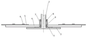
Fig. 1 is a partial cross-sectional view of the present invention;
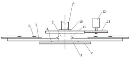
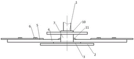
fig. 2 is an external front view of the present invention;
FIG. 3 is a schematic view of the driving gear assembly of the present invention;
wherein:
1 dead lever 2 limiting plate
3 spacer 4 rotating disc
5 cutting blade 6 fixing bolt
No. 8 bearing for 7 assembling set
No. 9 II bearing 10 driven gear
11 ribbed plate 12 driving motor
13 drive gear.
Detailed Description
The present invention will be described in detail below with reference to the accompanying drawings and examples:
as shown in fig. 1-3, a blade disc drive structure of lawn mower, including dead lever 1, the cover has assembly cover 7 that can rotate on the dead lever 1, 7 outer wall departments of assembly cover are provided with rolling disc 4, 1 lower extreme of dead lever is provided with carries out the limiting plate 2 that the axial supported to assembly cover 7, rolling disc 4, be provided with a plurality of cutting blade 5 on the rolling disc 4, rolling disc 4 is visited to cutting blade 5's front end.
The fixed rod 1 is further sleeved with a gasket 3, one end of the gasket 3 is in contact with the rotating disc 4, and the other end of the gasket 3 is in contact with the limiting plate 2.
A bearing 8 and a bearing 9 II are arranged in the assembling sleeve 7, and the fixing rod 1 is fixed with the inner rings of the bearing 8 and the bearing 9 II.
And a driving assembly for driving the assembling set 7 to rotate is arranged on the outer wall of the assembling set.
The driving assembly comprises a driven gear 10 arranged on the outer wall of the assembling sleeve 7, and the driven gear 10 is meshed with a driving gear 13 on a main shaft of a driving motor 12.
The driving motor 12 and the fixing rod 1 are both arranged and fixed with the frame of the mower.
A plurality of ribbed plates 11 for reinforcement are arranged between the assembling sleeve 7 and the rotating disc 4.
The cutting blade 5 is fixed to the rotating disk 4 by a fixing bolt 6. The cutting blade 5 is formed with a through hole, the rotating disk 4 is formed with a threaded counter bore, and the fixing bolt 6 is threaded into the threaded counter bore through the through hole.
Each cutting blade 5 requires at least two fixing bolts 6 for fixing, and the extension line of the cutting blade 5 passes through the axis of the rotating disk 4.
Preferably, the cutting blades 5 are arranged at equal angular intervals.
The rotating disc 4 and the assembling sleeve 7 are integrated, and the rib plates 11 are welded with the rotating disc 4 and the assembling sleeve 7.
The fixing rod 1 and the limiting plate 2 are integrated.
The fixing mode between the assembling set 7 and the driven gear 10 is key connection.
The working process of the utility model is as follows:
start driving motor 12, driving motor 12 drives driving gear 13 and rotates to drive driven gear 10 rotates, driven gear 10 pivoted simultaneously drives the dress and matches 7, carousel 4 and rotates, No. I bearing 8, No. II bearing 9's outer lane rotate, and the inner circle links to each other with dead lever 1 and keeps motionless, thereby carousel 4 can drive cutting blade 5 high-speed rotation and realize the pruning to the vegetation.
The utility model discloses a dead lever is for the dress form group, the rotation of rolling disc realizes the direction basis, has realized through limiting plate, gasket that the basis of having hoisted, through built-in bearing No. I in the assembly cover, No. II bearings can reduce the friction between dead lever, the assembly cover, the drive is through the driving gear meshing realization that the driving gear on the outer driven gear of dress form group, driving motor, can realize the speed governing through the gear ratio simultaneously, the utility model discloses the high-speed rotation of effectual realization blade disc.
Claims (8)
1. The utility model provides a blade disc drive structure of lawn mower, includes dead lever (1), its characterized in that: the cover has can pivoted dress cover (7) on dead lever (1), dress cover (7) outer wall department is provided with rolling disc (4), dead lever (1) lower extreme is provided with carries out limiting plate (2) that axial supported to dress cover (7), rolling disc (4), be provided with a plurality of cutting blade (5) on rolling disc (4), rolling disc (4) are visited to the front end of cutting blade (5).
2. The cutter head driving structure of a lawnmower according to claim 1, wherein: the fixed rod (1) is further sleeved with a gasket (3), one end of the gasket (3) is in contact with the rotating disc (4), and the other end of the gasket (3) is in contact with the limiting plate (2).
3. The cutter head driving structure of a lawnmower according to claim 2, wherein: be provided with bearing (8) No. I, bearing (9) No. II in the equipment cover (7), dead lever (1) is fixed mutually with the inner circle of bearing (8) No. I, bearing (9) No. II.
4. The cutter head driving structure of a lawnmower according to claim 3, wherein: and a driving assembly for driving the assembly to rotate is arranged on the outer wall of the assembly set (7).
5. The cutter head driving structure of a lawnmower according to claim 4, wherein: the driving assembly comprises a driven gear (10) arranged on the outer wall of the assembly set (7), and the driven gear (10) is meshed with a driving gear (13) on a main shaft of a driving motor (12).
6. The cutter head driving structure of a lawnmower according to claim 5, wherein: the driving motor (12) and the fixing rod (1) are both arranged and fixed with the mower rack.
7. The cutter head driving structure of a lawnmower according to claim 3, wherein: a plurality of ribbed plates (11) for reinforcement are arranged between the assembling sleeve (7) and the rotating disc (4).
8. The cutter head driving structure of a lawnmower according to claim 1, wherein: the cutting blade (5) is fixed to the rotating disc (4) by a fixing bolt (6).
Priority Applications (1)
| Application Number | Priority Date | Filing Date | Title |
|---|---|---|---|
| CN202020934167.6U CN213127128U (en) | 2020-05-28 | 2020-05-28 | Cutter head driving structure of mower |
Applications Claiming Priority (1)
| Application Number | Priority Date | Filing Date | Title |
|---|---|---|---|
| CN202020934167.6U CN213127128U (en) | 2020-05-28 | 2020-05-28 | Cutter head driving structure of mower |
Publications (1)
| Publication Number | Publication Date |
|---|---|
| CN213127128U true CN213127128U (en) | 2021-05-07 |
Family
ID=75723887
Family Applications (1)
| Application Number | Title | Priority Date | Filing Date |
|---|---|---|---|
| CN202020934167.6U Active CN213127128U (en) | 2020-05-28 | 2020-05-28 | Cutter head driving structure of mower |
Country Status (1)
| Country | Link |
|---|---|
| CN (1) | CN213127128U (en) |
-
2020
- 2020-05-28 CN CN202020934167.6U patent/CN213127128U/en active Active
Similar Documents
| Publication | Publication Date | Title |
|---|---|---|
| CN210694972U (en) | New forms of energy intelligence lawn mower | |
| CN207573930U (en) | A kind of reversed safety cover type locker disk mower | |
| CN107950172A (en) | A kind of bidirectional rotation cutterhead shear | |
| CN213127128U (en) | Cutter head driving structure of mower | |
| CN108668605B (en) | Removable formula gardens lawn mower | |
| CN107750587A (en) | A kind of reverse disk mower | |
| CN213127121U (en) | Blade disc antiwind structure of lawn mower | |
| CN214902213U (en) | Self-propelled mower | |
| CN213127127U (en) | Supporting structure of cutter head in mower | |
| CN205883998U (en) | Agricultural weeder of hand -held | |
| CN210868784U (en) | Self-propelled stubble-cutting and collecting mower | |
| CN210470303U (en) | Flexible shaft transmission all-terrain remote control mower | |
| CN114208482A (en) | Grass cutter | |
| CN207706727U (en) | A kind of bidirectional rotation cutterhead shear | |
| CN211020024U (en) | Small hand-push type lawnmower | |
| CN213127125U (en) | Lifting adjusting structure of mower cutter head | |
| CN214070689U (en) | Grass cutter | |
| CN220935686U (en) | Garden trimming and mowing device | |
| CN108293409B (en) | Mower with multidirectional cutter assembly | |
| CN201263307Y (en) | Grass mower | |
| CN219834888U (en) | Running gear that lawn mower was used | |
| CN219698478U (en) | Blade mounting base convenient for blade replacement for mowing robot | |
| CN214070692U (en) | Lawnmower that trigeminy was pruned | |
| CN217591555U (en) | Hand propelled lawn trimmer | |
| CN210808350U (en) | Hedge trimming cutter mounting assembly |
Legal Events
| Date | Code | Title | Description |
|---|---|---|---|
| GR01 | Patent grant | ||
| GR01 | Patent grant |