CN213071806U - Spareribs type AC low-voltage power distribution cabinet - Google Patents
Spareribs type AC low-voltage power distribution cabinet Download PDFInfo
- Publication number
- CN213071806U CN213071806U CN202022080503.8U CN202022080503U CN213071806U CN 213071806 U CN213071806 U CN 213071806U CN 202022080503 U CN202022080503 U CN 202022080503U CN 213071806 U CN213071806 U CN 213071806U
- Authority
- CN
- China
- Prior art keywords
- cabinet body
- female
- function unit
- cable
- feed function
- Prior art date
- Legal status (The legal status is an assumption and is not a legal conclusion. Google has not performed a legal analysis and makes no representation as to the accuracy of the status listed.)
- Active
Links
Images


Abstract
The utility model discloses a spareribs type AC low-voltage power distribution cabinet, including the cabinet body and outer door, the outer door rotates and installs at the cabinet body, the front side of the cabinet body is equipped with the female installing zone of arranging of level and feed function unit district, the female installing zone setting of level is female arranging of fixed mounting has the level at cabinet body top and level and is female arranging the row, cabinet body top is rotated and is installed the female apron of arranging of level, feed function unit district separates through the female installing zone of horizontal division board and level. The utility model discloses electric power passes cabinet body top outlet plate through the wire and gets into the cabinet body, connect the level of the female row of arranging in the horizontal busbar installing zone and transmit the perpendicular female row of arranging the installing zone to the perpendicular, the feed function unit of retransmission to feed function unit district, form rib type distribution structure, be favorable to user's connecing electric and maintenance, feed function unit passes through wire and the indoor distribution device electric connection of cable, the internal circuit passageway that sets up the outlet zone for perpendicular female row and distribution device interconnecting link that sets up of cabinet.
Description
Technical Field
The utility model relates to a switch board field, concretely relates to spareribs type AC low voltage power switch board.
Background
The high reliability of the use of low-voltage complete equipment is improved, the intelligent, modularized and miniaturized design of the equipment is ensured, the development trend of the current low-voltage distribution control cabinet is realized, and in recent years, various brand companies at home and abroad push out a plurality of new products, typically Blokset cabinets of Schneider, MNS cabinets of ABB and 8PT cabinets of Siemens company. The common characteristics of the products are that the modulization and standardization design is adopted, all the functional units are reasonably separated in the power distribution cabinet, the power distribution cabinet is safe and reliable to use and convenient to maintain, and is approved by users, but for some special users, when the space of the power distribution cabinet is limited, the power distribution loops are many, and the power distribution cabinet with higher volume rate of a single cabinet loop and less floor area of the cabinet is needed to improve the space utilization rate of the power distribution cabinet.
SUMMERY OF THE UTILITY MODEL
The utility model mainly aims at providing a spareribs type AC low voltage power distribution cabinet can effectively solve the problem in the background art.
In order to achieve the above purpose, the utility model discloses a following technical scheme realizes:
the rib type alternating-current low-voltage power distribution cabinet comprises a cabinet body and an outer door, wherein the outer door is rotatably installed on the cabinet body, a horizontal busbar installation area and a feeding function unit area are arranged on the front side of the cabinet body, the horizontal busbar installation area is arranged at the top of the cabinet body and in the horizontal busbar area, a horizontal busbar is fixedly installed in the horizontal busbar area, a horizontal busbar cover plate is rotatably installed at the top of the cabinet body, and the feeding function unit area is separated from the horizontal busbar installation area through a horizontal separation plate;
the rear side of the cabinet body is equipped with cable chamber, the female installing zone that arranges perpendicularly, the cable chamber separates through cable chamber erection column and the female installing zone that arranges perpendicularly, fixed mounting has female arranging perpendicularly on the female installing zone of arranging perpendicularly, cabinet body rear side still is equipped with the wire-out area, the wire-out area sets up in cable chamber both sides, cabinet body top still is equipped with the level and changes the row of connecing perpendicularly, cabinet body top and the equal fixed mounting in bottom have the wire-out plate.
The cabinet body is assembled by C section bars and G section bars which are most commonly used in China, can realize seamless splicing with GCK, GCS, MNS and the like of common cabinet types in China, and has very wide product applicability. Compared with the prior art, the cabinet body is formed by combining the original two cabinets, the length of the horizontal busbar is saved by 33%, the manufacturing cost of the preliminarily estimated cabinet body can be saved by 40%, and the total consumption of the busbar can be saved by 35%.
Preferably, the feeding function unit area is provided with an inner door upright post, and the feeding function unit area is divided into a left feeding function unit area and a right feeding function unit area by a function unit partition plate.
Preferably, the vertical busbar mounting area is separated from the line outlet area by a vertical busbar mounting post, and a vertical busbar rear sealing plate is fixedly mounted on the vertical busbar mounting post.
Preferably, fixed mounting has a plurality of feed function unit in the feed function unit district, the feed function unit includes the feed unit mounting panel, fixed mounting has operation inner door and cable splitter on the feed unit mounting panel, fixed mounting has the distribution to be qualified for the next round of competitions female arranging and current transformer on the cable splitter, the distribution is qualified for the next round of competitions female arranging and the perpendicular female electric connection that arranges, be provided with main switch between operation inner door and the cable splitter.
Preferably, a distribution branch busbar is further arranged on the cable partition plate, and the distribution branch busbar is electrically connected to a distribution device of the cable chamber.
Preferably, an extension rotation operating mechanism is fixedly mounted on the main switch, and the extension rotation operating mechanism penetrates through the operation inner door and is fixed on the surface of the operation inner door.
Preferably, the side wall of the cabinet body is fixedly provided with a cable binding frame, and the cable binding frame is fixedly provided with N rows and PE rows.
The utility model provides a rib type AC low voltage power distribution cabinet possesses following beneficial effect: electric power passes through the cabinet body top outlet plate through the wire and gets into the cabinet body, connect the horizontal female row in the horizontal female row installing zone and transmit to the perpendicular female row of arranging the installing zone of arranging perpendicularly, and then transmit to the feed function unit in feed function unit district, form rib type distribution structure, be favorable to user's electricity and maintenance, feed function unit passes through wire and the indoor distribution device electric connection of cable, the internal circuit passageway that sets up the outlet zone for perpendicular female row and distribution device interconnecting link that is of cabinet.
Drawings
In order to more clearly illustrate the embodiments of the present invention or the technical solutions in the prior art, the drawings used in the description of the embodiments or the prior art will be briefly described below.
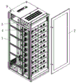
Fig. 1 is a schematic external structural view of the present invention;
fig. 2 is a schematic structural view of the cabinet body of the present invention;
FIG. 3 is a schematic view of the side structure of the cabinet body of the present invention;
FIG. 4 is a schematic cross-sectional view taken along line A-A of FIG. 3;
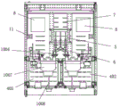
FIG. 5 is a schematic cross-sectional view taken along line B-B of FIG. 3;
fig. 6 is a schematic front view of the present invention;
FIG. 7 is a schematic cross-sectional view taken at C-C in FIG. 6;
fig. 8 is a schematic structural diagram of a feeding function unit of the present invention;
in the figure: 1. a cabinet body; 2. an outer door; 3. a horizontal busbar mounting area; 301. a horizontal busbar cover plate; 302. a horizontal partition plate; 303. a horizontal busbar; 304. horizontally and vertically switching rows; 4. a feed function unit region; 401. a functional unit partition plate; 402. a left feeding functional unit area; 403. a right feeding functional unit area; 404. an inner door pillar; 5. a cable chamber; 6. a cable chamber mounting post; 7. a vertical busbar mounting area; 701. a vertical busbar mounting post; 702. a vertical busbar rear sealing plate; 703. a vertical busbar; 8. a wire outlet area; 9. a wire outlet plate; 10. a feeding function unit; 1001. a feeding unit mounting plate; 1002. operating the inner door; 1003. a cable separator plate; 1004. a power distribution outlet bus bar; 1005. a current transformer; 1006. a power distribution branch busbar; 1007. a main switch; 1008. an extension rotation operation mechanism; 11. a cable tie bracket; 12. n rows and PE rows.
Detailed Description
In order to make the objects, technical solutions and advantages of the present invention clearer, the drawings of the present invention will be combined to clearly and completely describe the technical solutions in the embodiments of the present invention.
In the first embodiment, as shown in fig. 1 to 8, the rib type ac low-voltage power distribution cabinet includes a cabinet body 1 and an outer door 2, the outer door 2 is rotatably installed on the cabinet body 1, a horizontal busbar installation area 3 and a wire outlet plate area 4 are arranged on the front side of the cabinet body 1, the horizontal busbar installation area 3 is arranged on the top of the cabinet body 1, a horizontal busbar 303 is fixedly installed in the horizontal busbar installation area 3, a horizontal busbar cover plate 301 is rotatably installed on the top of the cabinet body 1, and the wire outlet plate area 4 is spaced from the horizontal busbar installation area 3 by a horizontal partition plate 302;
the rear side of the cabinet body 1 is equipped with cable chamber 5, the perpendicular female installing zone 7 that arranges, cable chamber 5 separates with perpendicular female installing zone 7 that arranges through 5 erection columns of cable chamber, and fixed mounting has perpendicular female arranging on the perpendicular female installing zone 7, and 1 rear side of the cabinet body still is equipped with wire-out zone 8, and wire-out zone 8 sets up in 5 both sides of cable chamber, and 1 top of the cabinet body still is equipped with horizontal perpendicular switching row 304, and 1 top of the cabinet body and the equal fixed mounting in bottom have wire-out plate 9. The outlet plate area 4 is provided with an inner door pillar 404, which facilitates the installation and fixation of the outlet plate 1010.
Electric power passes through cabinet body 1 top outlet plate 9 through the wire and gets into cabinet body 1, connect the female 303 of arranging of the horizontal mother in the horizontal mother installing zone 3 and arrange the perpendicular mother who transmits to the female installing zone 7 of arranging perpendicularly through the perpendicular switching of level, the outlet plate 10 of outlet plate district 4 is again transmitted, form rib type distribution structure, be favorable to user's connecing the electricity and maintaining, outlet plate 10 passes through wire and the distribution device electric connection in the cable chamber 5, cable chamber erection column 6 encloses into cable chamber 5 and forms the cable channel, set up outlet zone 8 in the cabinet body 1 and arrange the line channel of interconnecting link for perpendicular mother and distribution device. The horizontal busbar 303 is arranged in front of the cabinet top, a rear half cabinet outlet channel is reserved for a loop of the outlet plate 10, a user outlet wire can be arranged up and down, a user cable channel is designed and arranged on the left side and the right side of the rear side of the cabinet body 1, N rows and two sides of the PE row 12 are independently arranged, and the outlet rows of each outlet plate 10 loop are arranged up and down, so that the wiring and wiring of a user cable are very convenient.
In this implementation, the outlet board region 4 is divided into a left outlet board region 4024 and a right outlet board region 4034 by the functional unit partition board 401, the outlet board 10 is partitioned to divide the functions into blocks, the functional unit is designed in an interchangeable modular manner, a 3b partition mode is adopted in the power distribution cabinet, and the equipment is safe to operate and high in reliability coefficient.
In a second embodiment, as a preferred technical solution of the first embodiment, the vertical busbar mounting area 7 is separated from the outlet area 8 by a vertical busbar mounting post 701, and a vertical busbar rear sealing plate 702 is fixedly mounted on the vertical busbar mounting post 701. The vertical busbar mounting column 701 and the vertical busbar rear sealing plate 702 are convenient for mounting and fixing the vertical busbar.
Third embodiment, as a preferred technical solution of the first embodiment, a plurality of outlet boards 10 are fixedly installed in the outlet board area 4, each outlet board 10 includes a feeding unit installation board 1001, an operation inner door 1002 and a cable separation board 1003 are fixedly installed on the feeding unit installation board 1001, a distribution outlet busbar 1004 and a current transformer 1005 are fixedly installed on the cable separation board 1003, the distribution outlet busbar 1004 is electrically connected to a vertical busbar, and a main switch 1007 is arranged between the operation inner door 1002 and the cable separation board 1003.
The cable partition plate 1003 is further provided with a distribution branch busbar 1006, and the distribution branch busbar 1006 is electrically connected to an accessory of the cable chamber 5. An extension rotation operation mechanism 1008 is fixedly mounted on the main switch 1007, and the extension rotation operation mechanism 1008 penetrates the operation inner door 1002 and is fixed on the surface of the operation inner door 1002.
Each outlet plate 10 is provided with an operation inner door 1002, an extension rotation operation mode is adopted to open and close the main feed switch 1007, the operation is safe and convenient, the cabinet door is made of transparent glass, the appearance is attractive and elegant, the open and close states of the feed circuit switches are clear at a glance, the feed switches are plug-and-pull type circuit breakers, the product operation is safe and reliable, any circuit fault can be pulled out of the system, and the work of other circuits cannot be influenced.
Fourth, this embodiment is taken as an optimal technical scheme of first embodiment, and fixed mounting has cable tie frame 11 on the cabinet body 1 lateral wall, and cable tie frame 11 can fix and sign, and fixed mounting has N row and PE row 12 on the cable tie frame 11. In order to facilitate wiring and maintenance of users, N rows and PE rows 12 are arranged on two sides of the wire outlet plate area 4, and meanwhile, zero connection protection or grounding protection can be performed on a power distribution cabinet. The user cable channel is designed and arranged on the left side and the right side of the rear side of the cabinet, the N rows and the two sides of the PE row 12 are independently arranged, and the outgoing line rows of each feed circuit are arranged up and down, so that the user cable is very convenient to wire.
The above embodiments are only used to illustrate the technical solution of the present invention, and not to limit it; the front, the back, the left and the right of the utility model are only used for showing the mutual orientation of the parts in the drawings, and do not represent the actual orientation of the parts; although the present invention has been described in detail with reference to the foregoing embodiments, it should be understood by those skilled in the art that: the technical solutions described in the foregoing embodiments may still be modified, or some technical features may be equivalently replaced; such modifications and substitutions do not depart from the spirit and scope of the present invention in its corresponding aspects.
Claims (7)
1. Spareribs type AC low-voltage distribution cabinet, including the cabinet body and outer door, the outer door rotates and installs at the cabinet body, its characterized in that: a horizontal busbar mounting area and a feed function unit area are arranged on the front side of the cabinet body, the horizontal busbar mounting area is arranged at the top of the cabinet body, a horizontal busbar is fixedly mounted in the horizontal busbar, a horizontal busbar cover plate is rotatably mounted at the top of the cabinet body, and the feed function unit area is separated from the horizontal busbar mounting area through a horizontal partition plate;
the rear side of the cabinet body is equipped with cable chamber, the female installing zone that arranges perpendicularly, the cable chamber separates through cable chamber erection column and the female installing zone that arranges perpendicularly, fixed mounting has female arranging perpendicularly on the female installing zone of arranging perpendicularly, cabinet body rear side still is equipped with the wire-out area, the wire-out area sets up in cable chamber both sides, cabinet body top still is equipped with the level and changes the row of connecing perpendicularly, cabinet body top and the equal fixed mounting in bottom have the wire-out plate.
2. The spareribs type AC low voltage power distribution cabinet according to claim 1, characterized in that: the feed function unit district is provided with the inner door stand, the feed function unit district passes through the function unit division board and divide into left feed function unit district and right feed function unit district.
3. The spareribs type AC low voltage power distribution cabinet according to claim 1, characterized in that: the vertical busbar mounting area is separated from the wire outlet area through a vertical busbar mounting column, and a vertical busbar rear sealing plate is fixedly mounted on the vertical busbar mounting column.
4. The spareribs type AC low voltage power distribution cabinet according to claim 1, characterized in that: fixed mounting has a plurality of feed function unit in the feed function unit district, the feed function unit includes the feed unit mounting panel, fixed mounting has operation inner door and cable division board on the feed unit mounting panel, fixed mounting has the distribution to be qualified for the next round of competitions female arranging and current transformer on the cable division board, the distribution is qualified for the next round of competitions female arranging and the perpendicular female electric connection that arranges, be provided with main switch between operation inner door and the cable division board.
5. The spareribs type AC low voltage power distribution cabinet according to claim 4, characterized in that: the cable separator is also provided with a distribution branch busbar which is electrically connected to a distribution device of the cable chamber.
6. The spareribs type AC low voltage power distribution cabinet according to claim 4, characterized in that: and an extension rotary operating mechanism is fixedly mounted on the main switch, penetrates through the operation inner door and is fixed on the surface of the operation inner door.
7. The spareribs type AC low voltage power distribution cabinet according to claim 1, characterized in that: the cabinet is characterized in that a cable binding frame is fixedly mounted on the side wall of the cabinet body, and N rows and PE rows are fixedly mounted on the cable binding frame.
Priority Applications (1)
| Application Number | Priority Date | Filing Date | Title |
|---|---|---|---|
| CN202022080503.8U CN213071806U (en) | 2020-09-22 | 2020-09-22 | Spareribs type AC low-voltage power distribution cabinet |
Applications Claiming Priority (1)
| Application Number | Priority Date | Filing Date | Title |
|---|---|---|---|
| CN202022080503.8U CN213071806U (en) | 2020-09-22 | 2020-09-22 | Spareribs type AC low-voltage power distribution cabinet |
Publications (1)
| Publication Number | Publication Date |
|---|---|
| CN213071806U true CN213071806U (en) | 2021-04-27 |
Family
ID=75559556
Family Applications (1)
| Application Number | Title | Priority Date | Filing Date |
|---|---|---|---|
| CN202022080503.8U Active CN213071806U (en) | 2020-09-22 | 2020-09-22 | Spareribs type AC low-voltage power distribution cabinet |
Country Status (1)
| Country | Link |
|---|---|
| CN (1) | CN213071806U (en) |
-
2020
- 2020-09-22 CN CN202022080503.8U patent/CN213071806U/en active Active
Similar Documents
| Publication | Publication Date | Title |
|---|---|---|
| CA1170350A (en) | Multiple meter switchboard | |
| CN105914588A (en) | Multi-circuit-breaker power distribution cabinet or power distribution box | |
| CN213071806U (en) | Spareribs type AC low-voltage power distribution cabinet | |
| KR100641031B1 (en) | A switch board for a electric power apparatus | |
| CN105932550A (en) | Multi-circuit breaker arrangement method for power distribution cabinet or power distribution box | |
| CN202025987U (en) | Low-voltage switchgear assembly for small-sized mine | |
| CN208939368U (en) | A kind of double-bus high-tension switch cabinet | |
| CN203690788U (en) | Steel-clad movable-type AC metal enclosed switch cabinet | |
| CN201656276U (en) | Compact low voltage feed cabinet | |
| CN112421399B (en) | Power distribution cabinet with high space utilization rate | |
| CN205863763U (en) | Switch cubicle | |
| CN201360107Y (en) | Draw-out low-pressure switch cabinet with fixed partitions | |
| CN209948381U (en) | Low-voltage switch cabinet structure | |
| CN103701060A (en) | Steel-clad movable-type alternating current metal closed switch cabinet | |
| CN203415895U (en) | Low-voltage draw-out type switch device | |
| CN201674138U (en) | Box type fixed high-tension ring network switchgear | |
| CN208637857U (en) | A kind of novel multifunctional cable feeder pillar | |
| CN207853230U (en) | A kind of double frame circuit breaker low-voltage cabinets | |
| CN207925961U (en) | A kind of switch cabinet structure of three frame breaker outgoing line of band | |
| CN219286893U (en) | Inlet wire cabinet and switch cabinet group | |
| CN215870327U (en) | Novel hanging type switch cabinet structure | |
| CN218865975U (en) | Single-meter-position bus sharing type modular metering box | |
| CN220209684U (en) | Three-frame breaker integrated low-voltage cabinet | |
| CN214412027U (en) | Compact drawer type switch cabinet | |
| CN218040320U (en) | Intelligent control module for direct-current power supply cabinet |
Legal Events
| Date | Code | Title | Description |
|---|---|---|---|
| GR01 | Patent grant | ||
| GR01 | Patent grant |