CN213052171U - Right-angle plate stamping device - Google Patents
Right-angle plate stamping device Download PDFInfo
- Publication number
- CN213052171U CN213052171U CN202021672919.2U CN202021672919U CN213052171U CN 213052171 U CN213052171 U CN 213052171U CN 202021672919 U CN202021672919 U CN 202021672919U CN 213052171 U CN213052171 U CN 213052171U
- Authority
- CN
- China
- Prior art keywords
- rectangular hole
- cylinder
- roof pressure
- model
- movable block
- Prior art date
- Legal status (The legal status is an assumption and is not a legal conclusion. Google has not performed a legal analysis and makes no representation as to the accuracy of the status listed.)
- Active
Links
Images

Abstract
The utility model discloses a right angle sheet stamping device, including punching press mechanism and unloading mechanism, unloading mechanism is located one side of punching press mechanism, punching press mechanism includes frame, roof pressure subassembly and cylinder, the frame is provided with the model platform, the cylinder sets up in the frame, and the cylinder is located model bench side, the frame lower extreme is equipped with the bottom plate, the roof pressure subassembly sets up on the bottom plate, and the roof pressure subassembly is located model platform below, be equipped with the rectangular hole on the model platform, this rectangular hole supplies the roof pressure subassembly to stretch into, the cylinder lower extreme is provided with the briquetting, the briquetting is located the rectangular hole directly over, and briquetting and rectangular hole looks adaptation. The utility model discloses effectively improve the machining efficiency of right angle panel, and quick unloading that can be safe reduces the probability that people were hindered to machinery.
Description
Technical Field
The utility model relates to a processing technology field of sheet metal component specifically is a right angle panel stamping device.
Background
The punch press is a stamping type press. In national production, the stamping process has the advantages of material and energy conservation, high efficiency, low technical requirement on operators and capability of making products which cannot be machined through various die applications compared with the traditional machining, so that the stamping process has wider and wider application. The stamping production is mainly directed to plates. Through the mould, can make blanking, punch a hole, shaping, deep-drawing, trimming, essence towards, the plastic, riveting and extruded article etc. wide application in each field.
The part need be processed into right angled panel, and the punching machine can effectively improve work efficiency, but present shortcoming is, and the product of right angled panel is become in the punching press, is difficult to grab through finger cylinder or mechanical gripper and takes out, because of the punching machine is continuous work again, takes out through the manual work, has huge potential safety hazard. For this reason, we developed a right-angle sheet stamping device.
SUMMERY OF THE UTILITY MODEL
An object of the utility model is to provide a right angle panel stamping device has solved the problem among the above-mentioned background art.
In order to achieve the above object, the utility model provides a following technical scheme: the utility model provides a right angle sheet stamping device, includes punching press mechanism and unloading mechanism, unloading mechanism is located one side of punching press mechanism, punching press mechanism includes frame, roof pressure subassembly and cylinder, the frame is provided with the model platform, the cylinder sets up in the frame, and the cylinder is located model bench side, the frame lower extreme is equipped with the bottom plate, the roof pressure subassembly sets up on the bottom plate, and the roof pressure subassembly is located model platform below, be equipped with the rectangular hole on the model platform, this rectangular hole supplies the roof pressure subassembly to stretch into, the cylinder lower extreme is provided with the briquetting, the briquetting is located the rectangular hole directly over, and briquetting and rectangular hole looks adaptation.
Preferably, the roof pressure subassembly includes movable block and reset spring, the terminal surface is provided with guide post and two guide arms, two under the movable block the guide arm symmetry sets up in the guide post both sides, reset spring cup joints on the guide post, guide post and two guide arms run through the bottom plate, and guide post, two guide arms and bottom plate sliding connection, movable block and rectangular hole looks adaptation, and the movable block is located the rectangular hole, and reset spring is located between movable block and the bottom plate.
Preferably, the model platform is provided with a positioning groove, the positioning groove surrounds the rectangular hole, and the bottom surface of the positioning groove is flush with the top surface of the movable block.
Preferably, the blanking mechanism comprises a mechanical arm and an electromagnetic chuck, the mechanical arm comprises a large arm and a small arm, one end of the small arm is connected with the large arm, and the other end of the small arm is connected with the electromagnetic chuck.
Preferably, the mechanical arm can be a four-axis mechanical arm or a mechanical arm greater than four axes.
Compared with the prior art, the beneficial effects of the utility model are as follows:
1. the utility model discloses a set up punching press mechanism, it is used for fixing a position for not shaping panel to set up the constant head tank, make the accurate location processing of panel, the cylinder promotes the briquetting downwards, tight panel part under the briquetting, the movable block passes through compression spring and the also perpendicular downstream of guide post, not by the panel part of briquetting pressfitting, the inner wall extrusion through the rectangular hole is into perpendicular form, the cylinder resets the back, because compression spring's elasticity, the movable block also resets to keeping level with the constant head tank, and the product after the promotion shaping is located the constant head tank, the effect of quick machine-shaping right angle panel has been reached.
2. The utility model discloses a set up unloading mechanism, the forearm rotates, makes the one end displacement that is close to electromagnet to model platform front end, through electromagnet circular telegram, adsorbs the connection with the product vertical part, rotates through big arm, makes the forearm position shift out model platform, and will adsorb the product of connecting and take out, and electromagnet displacement is to placing the bench, and electromagnet cuts off the power supply, and the shaping panel falls to placing the platform, has reached the effect of quick safe unloading.
Drawings
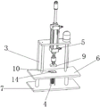
Fig. 1 is a schematic structural view of the present invention;
fig. 2 is a schematic mechanism diagram of the punching mechanism of the present invention.
The reference numerals and names in the figures are as follows:
1. a stamping mechanism; 2. a blanking mechanism; 3. a frame; 4. a jacking component; 5. a cylinder; 6. a model table; 7. a base plate; 9. briquetting; 10. a movable block; 11. a compression spring; 12. a guide post; 13. a guide bar; 14. positioning a groove; 15. a mechanical arm; 16. an electromagnetic chuck; 17. a large arm; 18. a small arm.
Detailed Description
The technical solutions in the embodiments of the present invention will be described clearly and completely with reference to the accompanying drawings in the embodiments of the present invention, and it is obvious that the described embodiments are only some embodiments of the present invention, not all embodiments. Based on the embodiments in the present invention, all other embodiments obtained by a person skilled in the art without creative work belong to the protection scope of the present invention.
Referring to fig. 1 to fig. 2, the present invention provides an embodiment: a right-angle plate stamping device comprises a stamping mechanism 1 and a blanking mechanism 2, wherein the blanking mechanism 2 is positioned on one side of the stamping mechanism 1, the stamping mechanism 1 comprises a rack 3, a jacking component 4 and a cylinder 5, the rack 3 is provided with a model platform 6, the cylinder 5 is arranged on the rack 3, the cylinder 5 is positioned above the model platform 6, the lower end of the rack 3 is provided with a bottom plate 7, the jacking component 4 is arranged on the bottom plate 7, the jacking component 4 is positioned below the model platform 6, the model platform 6 is provided with a rectangular hole for the jacking component 4 to extend into, the lower end of the cylinder 5 is provided with a pressing block 9, the pressing block 9 is positioned right above the rectangular hole, the pressing block 9 is matched with the rectangular hole, the blanking mechanism 2 comprises a mechanical arm 15 and an electromagnetic chuck 16, the mechanical arm 15 comprises a large arm 17 and a small arm 18, one end of the small arm 18 is connected with the large arm 17, the other end of the small arm 18 is connected to the electromagnetic chuck 16.
Specifically, roof pressure subassembly 4 includes movable block 10 and reset spring 11, the terminal surface is provided with guide post 12 and two guide arms 13 under the movable block 10, two guide arm 13 symmetry sets up in guide post 12 both sides, reset spring 11 cup joints on guide post 12, guide post 12 and two guide arms 13 run through bottom plate 7, and guide post 12, two guide arms 13 and bottom plate 7 sliding connection, movable block 10 and rectangular hole looks adaptation, and movable block 10 is located the rectangular hole, and reset spring 11 is located between movable block 10 and the bottom plate 7.
Wherein, the positioning groove 14 arranged on the model platform 6 is manufactured according to the shape of the processed product, the product is placed in the positioning groove 14, and the positioning groove 14 accurately fixes the unformed product, so that the unformed product cannot be deflected during processing.
The utility model discloses an unloading mechanism is applicable to ferromagnetic substance material, for example: iron, cobalt, nickel, and the like. The electromagnetic chuck 16 adsorbs a vertical portion of the front end of the processed connection product, and moves and takes out the connection product by the mechanical arm 15. Electromagnetic chuck 16 for permanent magnet, electromagnetic chuck 16 can adsorb with the product after the circular telegram and be connected, and after the outage, electromagnetic chuck 16 loses magnetism, then the product drops naturally, reaches the effect of quick unloading, and permanent magnet then adsorbable connection, can not accomplish naturally and drop, needs the manual work to take away, and arm 15's amplitude of oscillation, also can lead to the potential safety hazard, and permanent magnet can adsorb the material of taking magnetism in the workshop, then need increase the cost of labor to its regular cleaning.
In the operation of the utility model, firstly, an unformed plate is placed in the positioning groove 14, the air cylinder 5 drives the pressing block 9 to press downwards, the bottom end of the pressing block 9 contacts with a product and continuously presses downwards, the product part pressed by the pressing block 9 is embedded into the rectangular hole, the lower end of the part is pressed against the movable block 10, the other part is pressed into a vertical shape through the inner wall of the rectangular hole, the punching processing of the product is completed, the air cylinder 5 resets, the reset spring 11 jacks up the movable block 10 and the product on the movable block 10 to restore the original position, then the big arm 17 rotates to make the electromagnetic chuck 16 displace to the front end of the model table 6, the small arm 18 rotates to make the electromagnetic chuck 16 displace and adhere to the vertical part of the front end of the product, meanwhile, the electromagnetic chuck 16 is electrified to generate magnetism, the electromagnetic chuck 16 is connected with the product in an adsorption manner, the big arm 17 rotates to take out the, the formed sheet falls onto the placing table.
It is obvious to a person skilled in the art that the invention is not restricted to details of the above-described exemplary embodiments, but that it can be implemented in other specific forms without departing from the spirit or essential characteristics of the invention. The present embodiments are therefore to be considered in all respects as illustrative and not restrictive, the scope of the invention being indicated by the appended claims rather than by the foregoing description, and all changes which come within the meaning and range of equivalency of the claims are therefore intended to be embraced therein. Any reference sign in a claim should not be construed as limiting the claim concerned.
Claims (5)
1. The utility model provides a right angle sheet stamping device, includes punching press mechanism (1) and unloading mechanism (2), its characterized in that: blanking mechanism (2) are located one side of punching press mechanism (1), punching press mechanism (1) includes frame (3), roof pressure subassembly (4) and cylinder (5), frame (3) are provided with model platform (6), cylinder (5) set up in frame (3), and cylinder (5) are located model platform (6) top, frame (3) lower extreme is equipped with bottom plate (7), roof pressure subassembly (4) set up on bottom plate (7), and roof pressure subassembly (4) are located model platform (6) below, be equipped with the rectangular hole on model platform (6), this rectangular hole supplies roof pressure subassembly (4) to stretch into, cylinder (5) lower extreme is provided with briquetting (9), briquetting (9) are located the rectangular hole directly over, and briquetting (9) and rectangular hole looks adaptation.
2. The right-angle sheet punching device according to claim 1, wherein: roof pressure subassembly (4) are including movable block (10) and reset spring (11), terminal surface is provided with guide post (12) and two guide arms (13), two under movable block (10) guide arm (13) symmetry sets up in guide post (12) both sides, reset spring (11) cup joint on guide post (12), bottom plate (7) are run through in guide post (12) and two guide arms (13), and guide post (12), two guide arms (13) and bottom plate (7) sliding connection, movable block (10) and rectangular hole looks adaptation, and movable block (10) are located the rectangular hole, and reset spring (11) are located between movable block (10) and bottom plate (7).
3. The right-angle sheet punching device according to claim 1, wherein: and a positioning groove (14) is formed in the model platform (6), the positioning groove (14) surrounds the rectangular hole, and the bottom surface of the positioning groove (14) is flush with the top surface of the movable block (10).
4. The right-angle sheet punching device according to claim 1, wherein: the blanking mechanism (2) comprises a mechanical arm (15) and an electromagnetic chuck (16), the mechanical arm (15) comprises a large arm (17) and a small arm (18), one end of the small arm (18) is connected with the large arm (17), and the other end of the small arm (18) is connected with the electromagnetic chuck (16).
5. The right-angle sheet punching device according to claim 4, wherein: the mechanical arm (15) can be a four-axis mechanical arm or a mechanical arm larger than four axes.
Priority Applications (1)
| Application Number | Priority Date | Filing Date | Title |
|---|---|---|---|
| CN202021672919.2U CN213052171U (en) | 2020-08-12 | 2020-08-12 | Right-angle plate stamping device |
Applications Claiming Priority (1)
| Application Number | Priority Date | Filing Date | Title |
|---|---|---|---|
| CN202021672919.2U CN213052171U (en) | 2020-08-12 | 2020-08-12 | Right-angle plate stamping device |
Publications (1)
| Publication Number | Publication Date |
|---|---|
| CN213052171U true CN213052171U (en) | 2021-04-27 |
Family
ID=75582771
Family Applications (1)
| Application Number | Title | Priority Date | Filing Date |
|---|---|---|---|
| CN202021672919.2U Active CN213052171U (en) | 2020-08-12 | 2020-08-12 | Right-angle plate stamping device |
Country Status (1)
| Country | Link |
|---|---|
| CN (1) | CN213052171U (en) |
-
2020
- 2020-08-12 CN CN202021672919.2U patent/CN213052171U/en active Active
Similar Documents
| Publication | Publication Date | Title |
|---|---|---|
| CN202021269U (en) | Stamping die of side slide block with upward bending inner buckle | |
| CN213052171U (en) | Right-angle plate stamping device | |
| CN210497804U (en) | Flat copper bar forming device | |
| CN111545669A (en) | High brake shoe tile back of body automatic production line that rubs of freight train | |
| CN208004621U (en) | Full internal buckle flanging mould | |
| CN215785869U (en) | One-time stamping forming die for multi-fold protective cover | |
| CN215032882U (en) | Stamping die's auxiliary structure and stamping die | |
| CN205008487U (en) | Side plastic mould | |
| CN206747438U (en) | A kind of punch press stamping station | |
| CN212350107U (en) | Adjustable traceless bending die | |
| CN210475231U (en) | Hole flanging processing die for concentric holes | |
| CN219151339U (en) | Roller frame die for robot welding | |
| CN211441232U (en) | Ventilated membrane stamping and welding device | |
| CN216226463U (en) | Novel integral type plastic shaping structure | |
| CN215391747U (en) | Segment difference traceless mold structure capable of realizing double-bending and impressionless | |
| CN213288361U (en) | One-time punching multi-piece hardware cylindrical steel shell punching die | |
| CN209953642U (en) | Secondary bending die for high-current contact piece continuous stamping terminal | |
| CN218873547U (en) | Combined stamping die | |
| CN208583919U (en) | A kind of anti-deformation and the vehicle appliance product processing hardware dies that de- material can be postponed | |
| CN204584003U (en) | Cylindrical member side opening punch die | |
| CN213052292U (en) | Stamping jig for bent piece | |
| CN214601299U (en) | Stamping device for manufacturing die capable of being positioned quickly | |
| CN218191916U (en) | Unsettled turn-ups mould | |
| CN219274171U (en) | Large-scale elbow stamping device | |
| CN213563019U (en) | Mould with accurate locate function |
Legal Events
| Date | Code | Title | Description |
|---|---|---|---|
| GR01 | Patent grant | ||
| GR01 | Patent grant |