CN213048589U - Peritoneal dialysis locator suitable for kidney internal medicine patient - Google Patents
Peritoneal dialysis locator suitable for kidney internal medicine patient Download PDFInfo
- Publication number
- CN213048589U CN213048589U CN202021386624.9U CN202021386624U CN213048589U CN 213048589 U CN213048589 U CN 213048589U CN 202021386624 U CN202021386624 U CN 202021386624U CN 213048589 U CN213048589 U CN 213048589U
- Authority
- CN
- China
- Prior art keywords
- dialysis
- tube
- subassembly
- peritoneal dialysis
- fixed
- Prior art date
- Legal status (The legal status is an assumption and is not a legal conclusion. Google has not performed a legal analysis and makes no representation as to the accuracy of the status listed.)
- Expired - Fee Related
Links
- 238000000502 dialysis Methods 0.000 title claims abstract description 73
- 239000003814 drug Substances 0.000 title claims description 6
- 210000003734 kidney Anatomy 0.000 title claims description 5
- 230000006835 compression Effects 0.000 claims abstract description 20
- 238000007906 compression Methods 0.000 claims abstract description 20
- 238000002844 melting Methods 0.000 claims description 12
- 230000008018 melting Effects 0.000 claims description 11
- VYPSYNLAJGMNEJ-UHFFFAOYSA-N Silicium dioxide Chemical compound O=[Si]=O VYPSYNLAJGMNEJ-UHFFFAOYSA-N 0.000 claims description 10
- 239000000741 silica gel Substances 0.000 claims description 10
- 229910002027 silica gel Inorganic materials 0.000 claims description 10
- 229910001220 stainless steel Inorganic materials 0.000 claims description 4
- 239000010935 stainless steel Substances 0.000 claims description 4
- 230000000670 limiting effect Effects 0.000 abstract description 7
- 230000000694 effects Effects 0.000 abstract description 4
- 238000006073 displacement reaction Methods 0.000 abstract description 2
- 238000000926 separation method Methods 0.000 abstract description 2
- 239000000385 dialysis solution Substances 0.000 description 4
- 239000012943 hotmelt Substances 0.000 description 4
- 238000000034 method Methods 0.000 description 3
- 210000003200 peritoneal cavity Anatomy 0.000 description 3
- 239000000853 adhesive Substances 0.000 description 2
- 230000001070 adhesive effect Effects 0.000 description 2
- XLYOFNOQVPJJNP-UHFFFAOYSA-N water Substances O XLYOFNOQVPJJNP-UHFFFAOYSA-N 0.000 description 2
- 210000001015 abdomen Anatomy 0.000 description 1
- 210000001124 body fluid Anatomy 0.000 description 1
- 239000010839 body fluid Substances 0.000 description 1
- 230000007547 defect Effects 0.000 description 1
- 239000003792 electrolyte Substances 0.000 description 1
- 239000007788 liquid Substances 0.000 description 1
- 239000000463 material Substances 0.000 description 1
- 230000002503 metabolic effect Effects 0.000 description 1
- 206010034674 peritonitis Diseases 0.000 description 1
- 230000001360 synchronised effect Effects 0.000 description 1
- CEIZFXOZIQNICU-UHFFFAOYSA-N tenuazonic acid Chemical compound CCC(C)C1NC(=O)C(C(C)=O)=C1O CEIZFXOZIQNICU-UHFFFAOYSA-N 0.000 description 1
- 238000002627 tracheal intubation Methods 0.000 description 1
- 239000002699 waste material Substances 0.000 description 1
Images


Landscapes
- External Artificial Organs (AREA)
Abstract
The utility model discloses a peritoneal dialysis positioner suitable for a patient in nephrology department, which comprises a fixed component, an inner catheter component and an outer catheter component, the fixing component consists of a fixing pad, a sleeve cover, a compression rod and a clamping sleeve, the inner catheter component consists of a dialysis catheter, a pipe sleeve, a fixing block, a rubber pad and a clamping ring, the outer catheter component comprises a puncture tube, a limiting retainer ring and a connecting tube, the inner catheter component can be skillfully fixed through the elastic cutting sleeve type design, the problems of separation and displacement of the dialysis catheter are avoided, the good positioning effect is realized, secondly, cooperate centre gripping snap ring fixture, not only can realize that the interpolation of interior conduit subassembly and outer conduit subassembly links to each other, also can separate when receiving outside pulling power in addition, prevent that interior conduit subassembly from pulling the internal problem of breaking away from patient because of the outside, ensured peritoneal dialysis treatment's security.
Description
Technical Field
The utility model relates to a peritoneal dialysis technical field especially relates to a peritoneal dialysis locator suitable for kidney internal medicine patient.
Background
Uremic patients require regular dialysis. At present, a plurality of patients adopt a peritoneal dialysis mode, namely, peritoneal dialysis is carried out by inputting peritoneal dialysis solution from the outside of a human body through a pipeline, the electrolyte balance is maintained, the peritoneal dialysis process is to perfuse the dialysis solution in a serial connection and parallel connection mode, the peritoneal cavity is uniformly perfused for 2-4 hours through the pipeline according to the advice of doctors, the dialysis solution of metabolic wastes and redundant moisture is discharged from the peritoneal cavity through the pipeline and is then perfused with new peritoneal dialysis solution, the continuous circulation operation can continuously discharge vivotoxin and redundant moisture, and thus the patients need to permanently arrange a dialysis pipeline on the peritoneal cavity, so that the fixation of the dialysis pipeline is very important.
According to the above, the existing clinical peritoneal dialysis has many defects and problems due to the lack of a positioning and fixing device in the dialysis conduit part, specifically as follows;
1. when the dialysis tube is pulled by the outside, the tube is easy to loosen, which not only causes the liquid to overflow, but also causes the peritonitis.
2. And poor fixation can also cause damage to the pipeline and even separation from the body of the patient, which can cause secondary intubation of the patient and influence subsequent treatment operation.
Therefore, in view of the above drawbacks, it is necessary to design a peritoneal dialysis positioner suitable for nephrology patients.
SUMMERY OF THE UTILITY MODEL
The utility model discloses the technical problem that will solve lies in: provides a peritoneal dialysis positioner suitable for a patient in nephrology department, which solves the problems provided by the background technology.
In order to solve the technical problem, the technical scheme of the utility model is that: the utility model provides a peritoneal dialysis locator suitable for kidney internal medicine patient, includes fixed subassembly, interior conduit subassembly and outer conduit subassembly, fixed subassembly by fixed bolster, mantle, compression bar and cutting ferrule constitute, interior conduit subassembly by dialysis tube, pipe box, fixed block, rubber pad and snap ring constitute, outer conduit subassembly by puncture pipe, spacing retaining ring and connecting pipe constitute, interior conduit subassembly run through inside the fixed subassembly, interior conduit subassembly and fixed subassembly adopt sliding connection, outer conduit subassembly be located interior conduit subassembly right side, outer conduit subassembly and interior conduit subassembly adopt sliding connection, the mantle set firmly in fixed bolster top right side, mantle and fixed bolster adopt hot melt to be connected, the compression bar cunning locate the inside lower extreme of mantle, compression bar and mantle adopt sliding connection, the cutting ferrule set firmly in compression bar bottom, the cutting sleeve and the compression rod are integrally formed, the cutting sleeve and the fixing pad are in vertical sliding connection, the dialysis tube penetrates through the lower end inside the fixing pad, the dialysis tube and the fixing pad are in sliding connection, the tube sleeve is fixedly arranged on the right side of the dialysis tube, the tube sleeve and the dialysis tube are in internal and external threaded connection, the fixing block is fixedly arranged on the right side of the tube sleeve, the fixing block and the tube sleeve are integrally formed, the rubber pad is fixedly arranged inside the fixing block, the rubber pad and the fixing block are in hot-melt connection, the snap ring is fixedly arranged at the upper end and the lower end of the right side of the fixing block and is in hot-melt connection with the fixing block, the puncture tube penetrates through the rubber pad, the puncture tube and the rubber pad are in tight-fit connection, the limit check ring is fixedly arranged on the right side of the puncture tube, and the limit, the connecting pipe is fixedly arranged on the right side of the limiting check ring and is connected with the limiting check ring in a hot melting mode.
Further, the left side of the fixing pad is fixedly arranged on the application patch, the application patch is connected with the fixing pad through an adhesive, the lower ends of the fixing pad and the inner part of the application patch are provided with avoiding holes, and the avoiding holes are circular through holes.
Further, the spring is further fixedly arranged at the upper end inside the sleeve cover, the spring is connected with the sleeve cover in a hot melting mode, and the bottom of the spring is connected with the compression rod in a hot melting mode.
Further, dialysis tube outer wall left side still set firmly the silica gel cover, silica gel cover and dialysis tube adopt the hot melt to be connected, silica gel cover inside still be equipped with the dialysis hole of a plurality of quantity, the dialysis hole be circular through-hole, dialysis tube left side port still set firmly the water conservancy diversion cover pipe, water conservancy diversion cover pipe and dialysis tube integrated into one piece.
Furthermore, the clamping ring is made of stainless steel, and the outer side of the clamping ring is arc-shaped.
Compared with the prior art, the peritoneal dialysis positioner applicable to the patient with the nephrology department has the following advantages;
1. at first, through the design of elastic cutting sleeve type, can carry out ingenious fixed to the internal catheter subassembly, avoided the dialysis pipe to break away from, the problem of displacement, realized fine positioning action.
2. Secondly, cooperate centre gripping snap ring fixture, not only can realize that the interpolation of interior conduit subassembly and outer conduit subassembly links to each other, also can separate when receiving outside pulling power in addition, prevent that interior conduit subassembly from pulling the internal problem of breaking away from patient because of the outside, ensured peritoneal dialysis treatment's security.
Drawings
FIG. 1 is a front view of a peritoneal dialysis positioner adapted for use with a nephrology patient;
FIG. 2 is a perspective view of a peritoneal dialysis positioner suitable for use with a nephrology patient 1;
FIG. 3 is a perspective view of a peritoneal dialysis positioner suitable for use with a nephrology patient 2;
FIG. 4 is a perspective view of a peritoneal dialysis positioner suitable for use with a nephrology patient 3;
FIG. 5 is a perspective view of a peritoneal dialysis positioner suitable for use with a nephrology patient 4;
FIG. 6 is a perspective view of a peritoneal dialysis positioner for a nephrology patient in an isolated state 1;
FIG. 7 is a perspective view of a peritoneal dialysis positioner for a nephrology patient in an isolated state 2;
FIG. 8 is an enlarged perspective view of the inner catheter assembly and the outer catheter assembly;
fig. 9 is an enlarged perspective view of the spring portion.
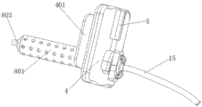
The device comprises a fixing component 1, an inner catheter component 2, an outer catheter component 3, a fixing pad 4, a sleeve cover 5, a compression rod 6, a clamping sleeve 7, a dialysis tube 8, a catheter sleeve 9, a fixing block 10, a rubber pad 11, a clamping ring 12, a puncture tube 13, a limiting check ring 14, a connecting tube 15, an application 401, an avoiding hole 402, a spring 501, a silica gel sleeve 801, a dialysis hole 802 and a flow guide cover tube 803.
The following detailed description will be further described in conjunction with the above-identified drawings.
Detailed Description
In the following description, numerous specific details are set forth in order to provide a thorough understanding of the concepts underlying the described embodiments, however, it will be apparent to one skilled in the art that the described embodiments may be practiced without some or all of these specific details, and in other cases well-known process steps have not been described in detail.
As shown in fig. 1, 2, 3, 4, 5, 6, 7, 8, 9, a peritoneal dialysis positioner suitable for a patient in renal medicine comprises a fixing component 1, an inner catheter component 2, an outer catheter component 3, a fixing pad 4, a sleeve cover 5, a compression rod 6, a cutting sleeve 7, a dialysis tube 8, a sleeve 9, a fixing block 10, a rubber pad 11, a snap ring 12, a puncture tube 13, a limit retainer ring 14, and a connecting tube 15, wherein the inner catheter component 2 penetrates through the inside of the fixing component 1, the inner catheter component 2 is in sliding connection with the fixing component 1, the outer catheter component 3 is positioned at the right side of the inner catheter component 2, the outer catheter component 3 is in sliding connection with the inner catheter component 2, the sleeve cover 5 is fixedly arranged at the right side of the top of the fixing pad 4, the sleeve cover 5 is in hot-melting connection with the fixing pad 4, the compression rod 6 is arranged at the lower end inside the sleeve cover 5 in a sliding manner, the compression rod 6 and the sleeve cover 5 are in sliding connection, the cutting sleeve 7 is fixedly arranged at the bottom of the compression rod 6, the cutting sleeve 7 and the compression rod 6 are integrally formed, the cutting sleeve 7 and the fixing pad 4 are in vertical sliding connection, the dialysis tube 8 penetrates through the lower end inside the fixing pad 4, the dialysis tube 8 and the fixing pad 4 are in sliding connection, the tube sleeve 9 is fixedly arranged at the right side of the dialysis tube 8, the tube sleeve 9 and the dialysis tube 8 are in internal and external threaded connection, the fixing block 10 is fixedly arranged at the right side of the tube sleeve 9, the fixing block 10 and the tube sleeve 9 are integrally formed, the rubber pad 11 is fixedly arranged inside the fixing block 10, the rubber pad 11 and the fixing block 10 are in hot melting connection, the snap ring 12 is fixedly arranged at the upper end and the lower end of the right side of the fixing block 10, the snap ring 12 and the fixing block 10 are in hot melting connection, the puncture tube 13 penetrates, the puncture tube 13 is tightly matched and connected with the rubber pad 11, the limit retainer ring 14 is fixedly arranged on the right side of the puncture tube 13, the limit retainer ring 14 is connected with the puncture tube 13 in a hot melting manner, the connecting tube 15 is fixedly arranged on the right side of the limit retainer ring 14, and the connecting tube 15 is connected with the limit retainer ring 14 in a hot melting manner;
it is noted that two functions are realized by the device when the patient is clinically subjected to peritoneal dialysis;
A. when the dialysis catheter is worn, the cutting sleeve 7 is pushed upwards in advance, the dialysis catheter 8 penetrates through the fixing pad 4 and is inserted into the body, the cutting sleeve 7 is convenient to slide downwards under the action of resilience force of the spring 501 by loosening the cutting sleeve 7, namely the cutting sleeve 7 is arranged on the outer side of the catheter sleeve 9 at the front end of the dialysis catheter 8, and at the moment, the inner catheter component 2 can be prevented from slipping and being discharged under the limiting action of the cutting sleeve 7;
B. the puncture tube 13 in the outer catheter component 3 can be inserted into the puncture rubber pad 11 under the action of force applied by medical personnel, the synchronous limiting retainer ring 14 is clamped into the rear end from the front end of the clamp ring 12, at the moment, the outer catheter component 3 and the inner catheter component 2 can be connected through the method, when pulling force is generated outside, the inner catheter component 2 is limited by the clamp sleeve 7, the clamp ring 12 has an elastic effect, the outer catheter component 3 can conveniently slip off the clamp ring 12, and the inner catheter component 2 is separated from the inner catheter component 2, at the moment, the inner catheter component 2 is prevented from being taken out, and when the puncture tube 13 is separated from the rubber pad 11, the puncture tube 13 can be plugged by the rebound resilience effect of the rubber material of the rubber pad 11, so that the problem of body fluid overflow is effectively prevented;
the left side of the fixing pad 4 is fixedly arranged on an application patch 401, the application patch 401 is connected with the fixing pad 4 by adopting an adhesive, the lower ends of the fixing pad 4 and the application patch 401 are also provided with avoidance holes 402, and the avoidance holes 402 are circular through holes;
the application 401 can be pasted on the abdomen of the patient to realize the connection and fixation of the fixing component 1 and the body of the patient, and the avoidance hole 402 can facilitate the dialysis tube 8 of the inner catheter component 2 to penetrate and be inserted into the body of the patient;
a spring 501 is fixedly arranged at the upper end inside the sleeve cover 5, the spring 501 is connected with the sleeve cover 5 in a hot melting manner, and the bottom of the spring 501 is connected with the compression rod 6 in a hot melting manner;
it should be noted that the spring 501 has resilience, and can rebound the lower end compression rod 6 downwards, so that the cutting ferrule 7 can restrain the inner catheter assembly 2 conveniently, when the inner catheter assembly needs to be taken out, the compression rod 6 slides upwards only by pushing the cutting ferrule 7 upwards, so that the resilience of the spring 501 is overcome, the cutting ferrule 7 cancels the limitation on the front end of the dialysis catheter 8, and the inner catheter assembly 2 is convenient to be taken out of the patient;
a silica gel sleeve 801 is fixedly arranged on the left side of the outer wall of the dialysis tube 8, the silica gel sleeve 801 is connected with the dialysis tube 8 in a hot melting mode, a plurality of dialysis holes 802 are further formed in the silica gel sleeve 801, the dialysis holes 802 are circular through holes, a diversion cover tube 803 is fixedly arranged at a port on the left side of the dialysis tube 8, and the diversion cover tube 803 and the dialysis tube 8 are integrally formed;
the silica gel sleeve 801 has good flexibility, which can improve soft contact with the body of a patient, and the dialysis hole 802 can facilitate the circulation and replacement of dialysate; the guide cover pipe 803 can be inserted conveniently to play a role in guiding;
the clamping ring 12 is made of stainless steel, and the outer side of the clamping ring 12 is arc-shaped;
it should be noted that, because the snap ring 12 is made of stainless steel, it has a good elastic effect, and can be opened to both sides by an external pulling force, even if the limiting check ring 14 is separated, the outer catheter assembly 3 and the inner catheter assembly 2 are separated.
Claims (5)
1. The utility model provides a peritoneal dialysis locator suitable for kidney internal medicine patient, its characterized in that includes fixed subassembly, interior conduit subassembly and outer conduit subassembly, fixed subassembly by fixed bolster, mantle, compression bar and cutting ferrule constitute, interior conduit subassembly by dialysis tube, pipe box, fixed block, rubber pad and snap ring constitute, outer conduit subassembly by puncture tube, spacing retaining ring and connecting pipe constitute, interior conduit subassembly run through inside the fixed subassembly, outer conduit subassembly be located the conduit subassembly right side, the mantle set firmly on fixed bolster top right side, the compression bar cunning locate the inside lower extreme of mantle, the cutting ferrule set firmly in the compression bar bottom, just cutting ferrule and fixed bolster adopt upper and lower sliding connection, the dialysis tube run through the inside lower extreme of fixed bolster, the pipe box set firmly on the dialysis tube right side, the fixed block set firmly on the pipe box right side, the rubber pad set firmly inside the fixed block, the snap ring set firmly both ends about the fixed block right side, the puncture pipe run through inside the rubber pad, spacing retaining ring set firmly in the puncture pipe right side, the connecting pipe set firmly in spacing retaining ring right side.
2. The peritoneal dialysis positioner for nephrology patients as claimed in claim 1, wherein the left side of the fixed pad is further fixedly arranged on the application patch, and the lower ends of the fixed pad and the application patch are further provided with avoiding holes.
3. The peritoneal dialysis positioner suitable for nephrology patients as claimed in claim 1, wherein a spring is further fixedly arranged at the upper end inside the shroud, and the bottom of the spring is connected with the compression rod by hot melting.
4. The peritoneal dialysis positioner suitable for nephrology patients as claimed in claim 1, wherein a silica gel sleeve is further fixedly arranged on the left side of the outer wall of the dialysis tube, a plurality of dialysis holes are further arranged in the silica gel sleeve, and a diversion cover tube is further fixedly arranged at a port on the left side of the dialysis tube.
5. The peritoneal dialysis positioner of claim 1, wherein the retainer ring is made of stainless steel.
Priority Applications (1)
| Application Number | Priority Date | Filing Date | Title |
|---|---|---|---|
| CN202021386624.9U CN213048589U (en) | 2020-07-15 | 2020-07-15 | Peritoneal dialysis locator suitable for kidney internal medicine patient |
Applications Claiming Priority (1)
| Application Number | Priority Date | Filing Date | Title |
|---|---|---|---|
| CN202021386624.9U CN213048589U (en) | 2020-07-15 | 2020-07-15 | Peritoneal dialysis locator suitable for kidney internal medicine patient |
Publications (1)
| Publication Number | Publication Date |
|---|---|
| CN213048589U true CN213048589U (en) | 2021-04-27 |
Family
ID=75573698
Family Applications (1)
| Application Number | Title | Priority Date | Filing Date |
|---|---|---|---|
| CN202021386624.9U Expired - Fee Related CN213048589U (en) | 2020-07-15 | 2020-07-15 | Peritoneal dialysis locator suitable for kidney internal medicine patient |
Country Status (1)
| Country | Link |
|---|---|
| CN (1) | CN213048589U (en) |
-
2020
- 2020-07-15 CN CN202021386624.9U patent/CN213048589U/en not_active Expired - Fee Related
Similar Documents
| Publication | Publication Date | Title |
|---|---|---|
| CN211410386U (en) | Hemodialysis pipeline fixation clamp | |
| CN213048589U (en) | Peritoneal dialysis locator suitable for kidney internal medicine patient | |
| CN210812904U (en) | A change and flow device for intestinal juice drainage | |
| CN210612629U (en) | Pressure sore prevention indwelling needle | |
| CN217724217U (en) | Circulation drainage bag | |
| CN216824471U (en) | Three-way connecting pipeline for hemodialysis | |
| CN210992274U (en) | Disposable indwelling needle | |
| CN111803740A (en) | Peritoneal dialysis cannula pipe easy to operate | |
| CN217592871U (en) | Safe hemostix for internal arteriovenous fistula | |
| CN210494856U (en) | Hemodialysis pjncture needle with it is fixed | |
| CN221600793U (en) | Drainage structure for urological department | |
| CN219127609U (en) | Leakage-proof urethral catheterization device for nursing in urology surgery | |
| CN221831292U (en) | ECMO remote perfusion device | |
| CN215231430U (en) | Hemodialysis nursing catheter fixing device | |
| CN215083058U (en) | Hemodialysis nursing vein keeps somewhere pipe lag | |
| CN213554268U (en) | Novel peritoneal dialysis waste liquid drainage bag | |
| CN216985880U (en) | Connecting pipe for hemodialysis extracorporeal circulation pipeline and blood vessel access | |
| CN216456290U (en) | Integrated blood circulation pipeline device for connecting perfusion device | |
| CN219185489U (en) | Special fixer for dialysis pipeline | |
| CN221535112U (en) | Double transfusion port dialysis structure | |
| CN213075629U (en) | Connector device for arterial puncture catheter | |
| CN219921804U (en) | Hemodialysis pipe fixing device | |
| CN214912416U (en) | Medical integrated blood purification extracorporeal circulation fixing device | |
| CN215134457U (en) | Special circulation pipeline for ascites ultrafiltration back transfusion abdominal cavity | |
| CN212547913U (en) | PICC exposes pipe fixer |
Legal Events
| Date | Code | Title | Description |
|---|---|---|---|
| GR01 | Patent grant | ||
| GR01 | Patent grant | ||
| CF01 | Termination of patent right due to non-payment of annual fee |
Granted publication date: 20210427 |
|
| CF01 | Termination of patent right due to non-payment of annual fee |