CN213043636U - Photovoltaic support convenient to install - Google Patents
Photovoltaic support convenient to install Download PDFInfo
- Publication number
- CN213043636U CN213043636U CN202021930246.6U CN202021930246U CN213043636U CN 213043636 U CN213043636 U CN 213043636U CN 202021930246 U CN202021930246 U CN 202021930246U CN 213043636 U CN213043636 U CN 213043636U
- Authority
- CN
- China
- Prior art keywords
- fixedly connected
- screw rod
- solar cell
- cell panel
- block
- Prior art date
- Legal status (The legal status is an assumption and is not a legal conclusion. Google has not performed a legal analysis and makes no representation as to the accuracy of the status listed.)
- Active
Links
Images

Classifications
-
- Y—GENERAL TAGGING OF NEW TECHNOLOGICAL DEVELOPMENTS; GENERAL TAGGING OF CROSS-SECTIONAL TECHNOLOGIES SPANNING OVER SEVERAL SECTIONS OF THE IPC; TECHNICAL SUBJECTS COVERED BY FORMER USPC CROSS-REFERENCE ART COLLECTIONS [XRACs] AND DIGESTS
- Y02—TECHNOLOGIES OR APPLICATIONS FOR MITIGATION OR ADAPTATION AGAINST CLIMATE CHANGE
- Y02E—REDUCTION OF GREENHOUSE GAS [GHG] EMISSIONS, RELATED TO ENERGY GENERATION, TRANSMISSION OR DISTRIBUTION
- Y02E10/00—Energy generation through renewable energy sources
- Y02E10/50—Photovoltaic [PV] energy
Abstract
The utility model discloses an install convenient photovoltaic support, including box, loading board and solar cell panel, there is the screw rod left side below swing joint of box inner chamber, and the surperficial threaded connection of screw rod has the thread bush, and the bottom sliding connection of thread bush is in the bottom of box inner chamber, the top fixedly connected with slider of thread bush. The utility model discloses people promote the clamp splice through the second spring and carry out the centre gripping with fixture block and solar cell panel, people move the turning handle through twisting, make the turning handle drive screw rod work, it removes left to drive the thread bush through the screw rod, it removes left to drive the slider through the thread bush, slide at the inner chamber of spacing groove through the slider and make the fly leaf skew upper left, solved current solar cell panel at the during operation, need use the photovoltaic support, the support of market selling is because simple structure can't install fast, and can not carry out angle modulation, lead to solar cell panel can not get into best operating condition's problem.
Description
Technical Field
The utility model relates to a solar photovoltaic support technical field specifically is a install convenient photovoltaic support.
Background
The solar photovoltaic support is a special support designed for placing, installing and fixing a solar panel in a solar photovoltaic power generation system, and is generally made of aluminum alloy, carbon steel and stainless steel.
SUMMERY OF THE UTILITY MODEL
An object of the utility model is to provide an install convenient photovoltaic support possesses the advantage of angle modulation, has solved current solar cell panel and at the during operation, need use the photovoltaic support, and the support of market selling is because simple structure can't install fast, and can not carry out angle modulation, leads to solar cell panel can not get into best operating condition's problem.
In order to achieve the above object, the utility model provides a following technical scheme: a photovoltaic bracket convenient to mount comprises a box body, a bearing plate and a solar cell panel, wherein a screw rod is movably connected with the lower part of the left side of an inner cavity of the box body, the surface of the screw rod is in threaded connection with a threaded sleeve, the bottom of the threaded sleeve is connected with the bottom of the inner cavity of the box body in a sliding manner, the top of the threaded sleeve is fixedly connected with a sliding block, the middle end of the left side of the inner cavity of the box body is fixedly connected with a positioning block, the right end of the positioning block is movably connected with a movable plate, the top of the box body is fixedly connected with a fixed block, the left side of the bottom of the bearing plate is movably connected in the inner cavity of the fixed block, the right end of the bottom of the bearing plate is fixedly connected with a movable block, the top of the sliding block is connected with the bottom of the movable plate in a sliding way, the right end of the top of the movable plate is movably connected with a fixed rod, the top of the fixed rod is movably connected to the bottom of the movable block, and the two ends of the solar cell panel are fixedly connected with clamping blocks.
Preferably, the equal fixedly connected with second spring in inner chamber both ends of loading board, the inboard fixedly connected with clamp splice of second spring, the inboard of clamp splice is used with the outside cooperation of fixture block, the spout has been seted up to the inboard of loading board, the bottom sliding connection of clamp splice is in the inner chamber of spout.
Preferably, the top of the inner cavity of the box body is fixedly connected with a first spring, and the bottom of the first spring is fixedly connected to the left side of the top of the movable plate.
Preferably, the right end of the screw rod is fixedly connected with a rotating handle, the right side of the inner cavity of the box body is fixedly connected with a limiting ring, the right end of the screw rod penetrates through the inner cavity of the limiting ring and is fixedly connected with the left side of the rotating handle, and the surface of the rotating handle is coated with an anti-slip coating.
Preferably, the bottom of the movable plate is provided with a limiting groove, and the top of the sliding block is slidably connected in an inner cavity of the limiting groove.
Compared with the prior art, the beneficial effects of the utility model are as follows:
1. the utility model discloses people promote the clamp splice through the second spring and carry out the centre gripping with fixture block and solar cell panel, people make the turning handle drive the screw rod work through twisting the turning handle, drive the thread bush through the screw rod and move left, drive the slider through the thread bush and move left, slide at the inner chamber of spacing groove through the slider and make the fly leaf skew left upper side, drive the dead lever through the fly leaf and move up, drive the movable block through the dead lever and move up, make the loading board skew through the movable block moves up, spacing through the fixed block to the loading board, make the loading board can carry out angle modulation, the effect of quick installation and angle modulation has been reached, solved current solar cell panel and in operation, need use the photovoltaic support, the support of selling in the market can't install fast because of simple structure, and can't carry out angle modulation, leading to the problem that the solar cell panel cannot enter the optimum working state.
2. The utility model discloses a setting of spacing groove, play spacing effect to the slider, make the slider shake can not appear when the motion, setting through the spacing ring, play the spacing effect to the screw rod, avoid the screw rod reversal to appear, lead to the unable regulation of angle, setting through first spring, make the work that the fly leaf is more stable, setting through second spring and clamp splice, can carry out the centre gripping installation to solar cell panel fast, save the extravagant time of installation, setting through the spout, play the spacing effect to the clamp splice, improve the stability of clamp splice.
Drawings
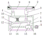
FIG. 1 is a front view of the structure of the present invention;
FIG. 2 is a sectional view of the structure of the present invention;
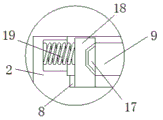
fig. 3 is a schematic view of a part of an enlarged structure at a in fig. 2 according to the present invention.
In the figure: 1. a box body; 2. a carrier plate; 3. a movable block; 4. a fixed block; 5. a handle is rotated; 6. a slider; 7. fixing the rod; 8. a chute; 9. a solar panel; 10. a first spring; 11. a movable plate; 12. positioning blocks; 13. a screw; 14. a limiting groove; 15. a threaded sleeve; 16. a limiting ring; 17. a clamping block; 18. a clamping block; 19. a second spring.
Detailed Description
The technical solutions in the embodiments of the present invention will be described clearly and completely with reference to the accompanying drawings in the embodiments of the present invention, and it is obvious that the described embodiments are only some embodiments of the present invention, not all embodiments. Based on the embodiments in the present invention, all other embodiments obtained by a person skilled in the art without creative work belong to the protection scope of the present invention.
In the description of the present invention, it should be noted that the terms "upper", "lower", "inner", "outer", "front end", "rear end", "both ends", "one end", "the other end", and the like indicate orientations or positional relationships based on the orientations or positional relationships shown in the drawings, and are only for convenience of description and simplification of description, but do not indicate or imply that the device or element to be referred must have a specific orientation, be constructed in a specific orientation, and be operated, and thus, should not be construed as limiting the present invention. Furthermore, the terms "first" and "second" are used for descriptive purposes only and are not to be construed as indicating or implying relative importance.
In the description of the present invention, it is to be noted that, unless otherwise explicitly specified or limited, the terms "mounted", "provided", "connected", and the like are to be construed broadly, such as "connected", which may be fixedly connected, detachably connected, or integrally connected; can be mechanically or electrically connected; they may be connected directly or indirectly through intervening media, or they may be interconnected between two elements. The specific meaning of the above terms in the present invention can be understood in specific cases to those skilled in the art.
The utility model discloses a box 1, loading board 2, movable block 3, fixed block 4, turning handle 5, slider 6, dead lever 7, spout 8, solar cell panel 9, first spring 10, fly leaf 11, locating piece 12, screw 13, spacing groove 14, thread bush 15, spacing ring 16, fixture block 17, clamp splice 18 and second spring 19 part are the parts that general standard or technical personnel in the field know, and its structure and principle all are this technical personnel and all can learn the manual or learn through conventional experimental approach through the technique.
Referring to fig. 1-3, a photovoltaic bracket convenient to mount comprises a box body 1, a bearing plate 2 and a solar cell panel 9, wherein a screw 13 is movably connected below the left side of the inner cavity of the box body 1, a threaded sleeve 15 is connected on the surface of the screw 13 in a threaded manner, the bottom of the threaded sleeve 15 is slidably connected to the bottom of the inner cavity of the box body 1, a slide block 6 is fixedly connected to the top of the threaded sleeve 15, a positioning block 12 is fixedly connected to the middle end of the left side of the inner cavity of the box body 1, a movable plate 11 is movably connected to the right end of the positioning block 12, a fixed block 4 is fixedly connected to the top of the box body 1, the left side of the bottom of the bearing plate 2 is movably connected to the inner cavity of the fixed block 4, a movable block 3 is fixedly connected to the right end of the bottom of the bearing plate 2, the two ends of the solar cell panel 9 are fixedly connected with clamping blocks 17, the two ends of the inner cavity of the bearing plate 2 are fixedly connected with second springs 19, the inner side of each second spring 19 is fixedly connected with a clamping block 18, the inner side of each clamping block 18 is matched with the outer side of the corresponding clamping block 17 for use, the inner side of the bearing plate 2 is provided with a sliding groove 8, the bottom of each clamping block 18 is slidably connected into the inner cavity of the corresponding sliding groove 8, the top of the inner cavity of the box body 1 is fixedly connected with a first spring 10, the bottom of the first spring 10 is fixedly connected to the left side of the top of the movable plate 11, the right end of the screw 13 is fixedly connected with a rotating handle 5, the right side of the inner cavity of the box body 1 is fixedly connected with a limiting ring 16, the right end of the screw 13 penetrates through the inner cavity of the limiting ring 16 and is fixedly connected with the left side of the rotating, through the setting of spacing groove 14, play spacing effect to slider 6, make slider 6 the shake can not appear when the motion, setting through spacing ring 16, play the spacing effect to screw rod 13, avoid screw rod 13 to appear reversing, lead to the unable regulation of angle, setting through first spring 10, make fly leaf 11 more stable work, setting through second spring 19 and clamp splice 18, can carry out the centre gripping installation to solar cell panel 9 fast, save the time of installing extravagant, setting through spout 8, play the spacing effect to clamp splice 18, improve the stability of clamp splice 18.
When the solar cell panel is used, people push the clamping block 18 to clamp the clamping block 17 and the solar cell panel 9 through the second spring 19, people twist the rotating handle 5 to enable the rotating handle 5 to drive the screw 13 to work, the screw 13 drives the threaded sleeve 15 to move leftwards, the threaded sleeve 15 drives the sliding block 6 to move leftwards, the sliding block 6 slides in the inner cavity of the limiting groove 14 to enable the movable plate 11 to deflect leftwards and upwards, the movable plate 11 drives the fixed rod 7 to move upwards, the fixed rod 7 drives the movable block 3 to move upwards, the movable block 3 moves upwards to enable the bearing plate 2 to deflect, the bearing plate 2 is limited through the fixed block 4, angle adjustment can be carried out on the bearing plate 2, the effects of quick installation and angle adjustment are achieved, the problem that the existing solar cell panel needs to use a photovoltaic bracket when in work is solved, and the bracket sold in the market cannot be installed quickly due, and the angle can not be adjusted, so that the solar cell panel can not enter the optimal working state.
Although embodiments of the present invention have been shown and described, it will be appreciated by those skilled in the art that changes, modifications, substitutions and alterations can be made in these embodiments without departing from the principles and spirit of the invention, the scope of which is defined in the appended claims and their equivalents.
Claims (5)
1. The utility model provides a photovoltaic support that installation is convenient, includes box (1), loading board (2) and solar cell panel (9), its characterized in that: the movable support is characterized in that a screw rod (13) is movably connected to the lower portion of the left side of an inner cavity of the box body (1), a threaded sleeve (15) is connected to the surface of the screw rod (13) in a threaded manner, the bottom of the threaded sleeve (15) is slidably connected to the bottom of the inner cavity of the box body (1), a sliding block (6) is fixedly connected to the top of the threaded sleeve (15), a positioning block (12) is fixedly connected to the middle end of the left side of the inner cavity of the box body (1), a movable plate (11) is movably connected to the right end of the positioning block (12), a fixed block (4) is fixedly connected to the top of the box body (1), a left side of the bottom of the bearing plate (2) is movably connected to the inner cavity of the fixed block (4), a movable block (3) is fixedly connected to the right end of the bottom of the bearing plate (, the top of the fixed rod (7) is movably connected to the bottom of the movable block (3), and the two ends of the solar cell panel (9) are fixedly connected with clamping blocks (17).
2. The photovoltaic bracket convenient to mount according to claim 1, characterized in that: the equal fixedly connected with second spring (19) in inner chamber both ends of loading board (2), inboard fixedly connected with clamp splice (18) of second spring (19), the inboard of clamp splice (18) and the outside cooperation of fixture block (17) are used, spout (8) have been seted up to the inboard of loading board (2), the bottom sliding connection of clamp splice (18) is in the inner chamber of spout (8).
3. The photovoltaic bracket convenient to mount according to claim 1, characterized in that: the top of the inner cavity of the box body (1) is fixedly connected with a first spring (10), and the bottom of the first spring (10) is fixedly connected to the left side of the top of the movable plate (11).
4. The photovoltaic bracket convenient to mount according to claim 1, characterized in that: the utility model discloses a box, including screw rod (13), box (1), right-hand member, inner chamber, the right side fixedly connected with turning handle (5) of screw rod (13), the right-hand member of screw rod (13) runs through the inner chamber of spacing ring (16) and is fixed connection with the left side of turning handle (5), the surface of turning handle (5) is scribbled and is equipped with anti-skidding coating.
5. The photovoltaic bracket convenient to mount according to claim 1, characterized in that: the bottom of the movable plate (11) is provided with a limiting groove (14), and the top of the sliding block (6) is connected in an inner cavity of the limiting groove (14) in a sliding mode.
Priority Applications (1)
| Application Number | Priority Date | Filing Date | Title |
|---|---|---|---|
| CN202021930246.6U CN213043636U (en) | 2020-09-07 | 2020-09-07 | Photovoltaic support convenient to install |
Applications Claiming Priority (1)
| Application Number | Priority Date | Filing Date | Title |
|---|---|---|---|
| CN202021930246.6U CN213043636U (en) | 2020-09-07 | 2020-09-07 | Photovoltaic support convenient to install |
Publications (1)
| Publication Number | Publication Date |
|---|---|
| CN213043636U true CN213043636U (en) | 2021-04-23 |
Family
ID=75534384
Family Applications (1)
| Application Number | Title | Priority Date | Filing Date |
|---|---|---|---|
| CN202021930246.6U Active CN213043636U (en) | 2020-09-07 | 2020-09-07 | Photovoltaic support convenient to install |
Country Status (1)
| Country | Link |
|---|---|
| CN (1) | CN213043636U (en) |
-
2020
- 2020-09-07 CN CN202021930246.6U patent/CN213043636U/en active Active
Similar Documents
| Publication | Publication Date | Title |
|---|---|---|
| CN213043636U (en) | Photovoltaic support convenient to install | |
| CN211183219U (en) | Power cable winding displacement supports fixing device | |
| CN209007342U (en) | A kind of fixture for data line production | |
| CN210112441U (en) | Multifunctional seat for electronic information engineering communication box | |
| CN210985995U (en) | Solar support convenient to angle regulation | |
| CN215493771U (en) | Concentrate table case convenient to installation | |
| CN205195635U (en) | Solar cell panel's fastening support | |
| CN212945234U (en) | Automatic positioning and clamping device of sheet metal riveting machine | |
| CN205396279U (en) | Intelligence supports in being electronic | |
| CN211350510U (en) | Circuit breaker capable of adjusting mounting groove | |
| CN212526627U (en) | Zinc-nickel redox flow battery laser welding fixture | |
| CN212258670U (en) | Electric push rod with positioning function | |
| CN213476134U (en) | Clamping device for electroplating motor shell | |
| CN220762306U (en) | Processing clamp for lower shell of new energy battery | |
| CN213976757U (en) | Plane anti-torsion screw rod | |
| CN217571551U (en) | Photoelectric device welding holder with adjustable clamping structure | |
| CN220673611U (en) | Compact frequency converter | |
| CN220050630U (en) | Brake pedal arm welding assembly | |
| CN218254007U (en) | Clamping tool for reversible metal cutting | |
| CN211083382U (en) | Electric power electrical equipment strutting arrangement | |
| CN211391624U (en) | Searchlight for lifeboat | |
| CN220719032U (en) | The method comprises the following steps of: nitrogen spring clamping tool for machining | |
| CN219740819U (en) | Electricity-saving device with voltage stabilizing function | |
| CN210123648U (en) | Built-in contactless transport mechanism of blue-ray disc library | |
| CN217718052U (en) | Low-voltage leakage finder |
Legal Events
| Date | Code | Title | Description |
|---|---|---|---|
| GR01 | Patent grant | ||
| GR01 | Patent grant |