CN213034245U - Numerical control processing is with quick chamfer equipment - Google Patents
Numerical control processing is with quick chamfer equipment Download PDFInfo
- Publication number
- CN213034245U CN213034245U CN202021607337.6U CN202021607337U CN213034245U CN 213034245 U CN213034245 U CN 213034245U CN 202021607337 U CN202021607337 U CN 202021607337U CN 213034245 U CN213034245 U CN 213034245U
- Authority
- CN
- China
- Prior art keywords
- box
- fixed mounting
- rod
- plate
- backup pad
- Prior art date
- Legal status (The legal status is an assumption and is not a legal conclusion. Google has not performed a legal analysis and makes no representation as to the accuracy of the status listed.)
- Expired - Fee Related
Links
Images

Landscapes
- Grinding And Polishing Of Tertiary Curved Surfaces And Surfaces With Complex Shapes (AREA)
Abstract
The utility model relates to the technical field of numerical control punching machines, in particular to a quick chamfering device for numerical control machining, which comprises a box body, wherein a feed inlet is formed in the back surface of the box body, a first supporting plate is arranged at the bottom of the back surface of the box body, first slide bars are fixedly arranged on the left side and the right side of the front surface of the first supporting plate, and a second supporting plate is fixedly arranged in an inner cavity of the front surface of each first slide bar, which penetrates through the box body through the feed inlet and extends to the box body; the utility model discloses a setting of box, first backup pad, first slide bar, second backup pad, slide, rack, fixed plate, first telescopic link, bull stick, connecting plate, plate body and screw rod has reached the purpose that can automatic feeding and upset, has solved current grinding device and when using, all needs the manual work to put the part into the incasement usually and polish, needs the manual work to overturn, can waste a large amount of time and manpower like this, and the problem of the inefficiency of polishing.
Description
Technical Field
The utility model relates to a numerical control punch technical field specifically is a numerical control processing is with quick chamfer equipment.
Background
The numerical control punch press is a digital control punch press for short, and is an automatic machine tool provided with a program control system, wherein the control system can logically process a program specified by a control code or other symbolic instructions and decode the program so as to enable the punch press to act and machine a part, chamfering refers to machining for cutting edges and corners of a workpiece into a certain inclined plane, and the chamfering is to remove burrs generated on the part due to machining, after machining, burrs exist on the edges of the part, and the burrs need to be ground, and then a grinding device can be used.
When the existing grinding device is used, parts are usually required to be manually placed in a box for grinding, the parts are required to be manually turned over, a large amount of time and manpower can be wasted, the grinding efficiency is low, and therefore the numerical control machining rapid chamfering equipment is provided.
SUMMERY OF THE UTILITY MODEL
An object of the utility model is to provide a numerical control processing is with quick chamfer equipment possesses the advantage that can automatic feeding and upset, has solved current grinding device and when using, all needs the manual work to put the part the incasement generally and polish, needs the manual work to overturn, can waste a large amount of time and manpower like this, and polish the problem of inefficiency.
In order to achieve the above object, the utility model provides a following technical scheme: a quick chamfering device for numerical control machining comprises a box body, wherein a feed inlet is formed in the back face of the box body, a first supporting plate is arranged at the bottom of the back face of the box body, first slide rods are fixedly mounted on the left side and the right side of the front face of the first supporting plate, a second supporting plate is fixedly mounted on the front face of the first slide rod, penetrates through the box body through the feed inlet and extends to the inner cavity of the box body, the bottom of the second supporting plate is fixedly mounted with the bottom of the inner cavity of the box body, a slide plate is slidably connected to the surface of the first slide rod, a placing frame is fixedly mounted at the top of the slide plate, a fixing plate is fixedly mounted at the top of the first supporting plate, a first telescopic rod is fixedly mounted at the top of the fixing plate, a telescopic end of the first telescopic rod penetrates through the feed inlet and extends to the inner cavity, the outside of bull stick and the inner chamber fixed mounting that is located the right side of box and runs through the box and extend to the box has the connecting plate, the equal fixed mounting in both ends about the connecting plate is inboard has the plate body, the inboard of plate body is provided with splint, and the top bearing of splint supports there is the screw rod, the top of screw rod runs through the plate body and extends to the outside of plate body.
Preferably, the top of box inner chamber both sides all fixed mounting have the second slide bar, the surperficial sliding connection of second slide bar has the slider, the front fixed mounting of slider has the second telescopic link.
Preferably, the right side fixed mounting of the flexible end bottom of second telescopic link has the motor, the output shaft fixed mounting of motor has the connecting rod, and the bottom fixed mounting of connecting rod has the driving gear, the left side fixed mounting of the flexible end bottom of second telescopic link has the casing, the inner chamber bearing support of casing has the body of rod, the surface of the body of rod and the inner chamber fixed mounting that is located the casing have a driven gear, microscler mouth has been seted up to the bottom on casing right side, the driving gear left side runs through the casing through microscler mouth and extends to the inner chamber and the driven gear meshing of casing, the outside fixed mounting that the bottom of the body of rod runs through the casing and extends to the casing.
Preferably, the outside fixed mounting of bull stick has the carousel, the right side fixed mounting of carousel has the rocker, circular mouth has been seted up on the left surface of carousel, the bottom on box right side and the left side fixed mounting that is located the carousel have the body, the inner chamber fixed mounting of body has the spring, the right side fixed mounting of spring has the block, and the right side of block runs through the body and extends to the outside of body and the inner chamber joint of circular mouth, and the positive fixed mounting of block has the pull rod.
Preferably, a support is supported on the surface of the rotating rod and positioned in an inner cavity bearing of the box body, and the bottom of the support and the bottom of the inner cavity of the box body are fixedly installed.
Preferably, the holding rod is fixedly mounted on the front face of the second telescopic rod, a sliding groove is formed in the top of the front face of the box body, and the front face of the holding rod penetrates through the box body through the sliding groove and extends to the outside of the box body.
Preferably, the bottom on box right side just is located the below fixed mounting of first backup pad and has the loading board, and the right side at loading board top and the bottom fixed mounting of first backup pad.
Preferably, the front surface of the box body is hinged with a box door, and the surface of the box door is provided with an observation port.
Compared with the prior art, the beneficial effects of the utility model are as follows:
1. the utility model discloses a setting of box, first backup pad, first slide bar, second backup pad, slide, rack, fixed plate, first telescopic link, bull stick, connecting plate, plate body and screw rod has reached the purpose that can automatic feeding and upset, has solved current grinding device and when using, all needs the manual work to put the part into the incasement usually and polish, needs the manual work to overturn, can waste a large amount of time and manpower like this, and the problem of the inefficiency of polishing.
2. The utility model discloses a flexible end of second telescopic link drives motor and casing while downstream, make the surface laminating of dull polish piece and part, setting through second slide bar and slider, can make the second telescopic link control the removal, output shaft through the motor drives the connecting rod and rotates, the connecting rod drives the driving gear rotation, it rotates to drive driven gear through the rotation of driving gear, driven gear drives the rod body rotation, the rotatory dull polish piece that drives through the body of rod rotates, through the motor, the driving gear, driven gear, the setting of casing and the body of rod, can lotus root dull polish piece provide power, can be quick polish to the material that needs to polish.
3. The utility model rotates by the rocking bar of the user, the rotating disc is driven to rotate by the rocking bar, the rotating rod is driven to rotate by the rotating disc, thereby the effect of saving labor is achieved, the pull rod is driven by the user to move the block body, the spring is driven to move by the block body, the right side of the block body is separated from the circular opening, the rotating disc can be rotated to turn over the part to be polished, meanwhile, the fixing effect is also achieved, the rotating rod can be supported by the bracket, the rotating rod is prevented from shaking when rotating, the surface of the part is polished by the left and right movement of the holding rod driven by the user, thereby the convenient effect is achieved, the holding rod can be conveniently moved left and right in the chute by the arrangement of the chute, the first supporting plate can be fixed by the loading plate, the first supporting plate is prevented from shaking, through the arrangement of the box door, the user can conveniently fix the, the condition and the effect of polishing the part can be conveniently observed by a user through the observation port.
Drawings
FIG. 1 is a schematic structural view of the present invention;
FIG. 2 is a front sectional view of the box body of the present invention;
FIG. 3 is a right side sectional view of the box body of the present invention;
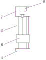
fig. 4 is a top view of the first slide bar of the present invention;
FIG. 5 is an enlarged view of the point A of FIG. 1 according to the present invention;
FIG. 6 is an enlarged view of the point B in FIG. 2 according to the present invention;
fig. 7 is a left side view of the turntable of the present invention.
In the figure: 1. a box body; 2. a first support plate; 3. a first slide bar; 4. a second support plate; 5. a slide plate; 6. placing a rack; 7. a fixing plate; 8. a first telescopic rod; 9. a rotating rod; 10. a connecting plate; 11. a plate body; 12. a screw; 13. a second slide bar; 14. a slider; 15. a second telescopic rod; 16. a motor; 17. a driving gear; 18. a housing; 19. a rod body; 20. a driven gear; 21. a turntable; 22. a pipe body; 23. a spring.
Detailed Description
The technical solutions in the embodiments of the present invention will be described clearly and completely with reference to the accompanying drawings in the embodiments of the present invention, and it is obvious that the described embodiments are only some embodiments of the present invention, not all embodiments. Based on the embodiments in the present invention, all other embodiments obtained by a person skilled in the art without creative work belong to the protection scope of the present invention.
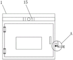
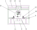
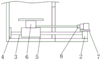
Referring to fig. 1-7, a fast chamfering device for numerical control machining comprises a box body 1, a feeding port is arranged on the back surface of the box body 1, a first supporting plate 2 is arranged at the bottom of the back surface of the box body 1, first slide bars 3 are fixedly arranged on the left side and the right side of the front surface of the first supporting plate 2, a second supporting plate 4 is fixedly arranged in an inner cavity of the box body 1 through the feeding port in the front surface of the first slide bars 3, the bottom of the second supporting plate 4 is fixedly arranged with the bottom of the inner cavity of the box body 1, a slide plate 5 is slidably connected to the surface of the first slide bars 3, a placing frame 6 is fixedly arranged at the top of the slide plate 5, a fixed plate 7 is fixedly arranged at the top of the first supporting plate 2, a first telescopic rod 8 is fixedly arranged at the top of the fixed plate 7, and the telescopic end of the first telescopic, the bottom of the two sides of the inner cavity of the box body 1 is supported by a rotating rod 9 through a bearing, the right side of the rotating rod 9, which is positioned at the outer side of the box body 1, penetrates through the box body 1 and extends to the inner cavity of the box body 1, is fixedly provided with a connecting plate 10, the upper end and the lower end of the inner side of the connecting plate 10 are fixedly provided with plate bodies 11, the inner side of each plate body 11 is provided with a clamping plate, the top of each clamping plate is supported by a screw rod 12, the top of each screw rod 12 penetrates through the plate bodies 11 and extends to the outer part of each plate body 11, the purposes of automatic feeding and overturning are achieved through the box body 1, the first support plate 2, the first slide rod 3, the second support plate 4, the slide plate 5, the placing rack 6, the fixing plate 7, the first telescopic rod 8, the rotating rod 9, the connecting plate 10, the plate bodies 11 and the screw rods 12, the problems that, and the polishing efficiency is low.
In this embodiment, specifically, the top of the two sides of the inner cavity of the box body 1 is fixedly provided with a second slide bar 13, the surface of the second slide bar 13 is connected with a slide block 14 in a sliding manner, the front surface of the slide block 14 is fixedly provided with a second telescopic rod 15, the telescopic end of the second telescopic rod 15 drives the motor 16 and the shell 18 to move downwards simultaneously, so that the sanding sheet is attached to the surface of the part, and the second telescopic rod 15 can move left and right through the arrangement of the second slide bar 13 and the slide block 14.
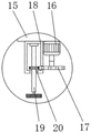
In this embodiment, specifically, a motor 16 is fixedly installed on the right side of the bottom of the telescopic end of the second telescopic rod 15, a connecting rod is fixedly installed on an output shaft of the motor 16, a driving gear 17 is fixedly installed on the bottom of the connecting rod, a housing 18 is fixedly installed on the left side of the bottom of the telescopic end of the second telescopic rod 15, a rod body 19 is supported by a cavity bearing of the housing 18, a driven gear 20 is fixedly installed on the surface of the rod body 19 and located in the cavity of the housing 18, a long opening is opened on the bottom of the right side of the housing 18, the left side of the driving gear 17 penetrates through the housing 18 through the long opening and extends to the cavity of the housing 18 to be meshed with the driven gear 20, a sanding sheet is fixedly installed on the bottom of the rod body 19 and extends to the outside of the housing 18, the connecting rod is driven, driven gear 20 drives the body of rod 19 rotatory, and the rotatory dull polish piece that drives through the body of rod 19 rotates, through motor 16, driving gear 17, driven gear 20, casing 18 and the setting of the body of rod 19, can lotus root dull polish piece provide power, can be quick polish the material that needs were polished.
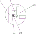
In the embodiment, specifically, a turntable 21 is fixedly installed on the outer side of the rotating rod 9, a rocker is fixedly installed on the right side of the turntable 21, a circular opening is formed in the surface of the left side of the turntable 21, a pipe body 22 is fixedly installed at the bottom of the right side of the box body 1 and on the left side of the turntable 21, a spring 23 is fixedly installed in an inner cavity of the pipe body 22, a block is fixedly installed on the right side of the spring 23, the right side of the block penetrates through the pipe body 22 and extends to the outside of the pipe body 22 to be clamped with the inner cavity of the circular opening, a pull rod is fixedly installed on the front side of the block, the rocker is shaken by a user to rotate, the turntable 21 is driven by the rocker to rotate, so that the labor-saving effect is achieved, the pull rod is pulled by the user to drive the block to move, the spring 23 is driven by the, meanwhile, the fixing effect is achieved.
In this embodiment, it is concrete, the surface of bull stick 9 and the inner chamber bearing that is located box 1 support there is the support, and the bottom of support and the bottom fixed mounting of box 1 inner chamber can support bull stick 9 through the support, prevents that bull stick 9 from producing when rotating and rocking.
In this embodiment, specifically, the positive fixed mounting of second telescopic link 15 has the holding rod, and the spout has been seted up at the positive top of box 1, and the front of holding rod runs through box 1 and extends to box 1's outside through the spout, moves about through user's pulling holding rod and removes the surface of coming the part and polish to reach convenient effect, through the setting of spout, can make things convenient for the holding rod to remove about in the spout.
In this embodiment, it is concrete, the bottom on box 1 right side and the below fixed mounting that is located first backup pad 2 have a loading board, and the right side at loading board top and the bottom fixed mounting of first backup pad 2 can be fixed first backup pad 2 through the loading board, prevents that first backup pad 2 from rocking.
In this embodiment, it is concrete, the front of box 1 articulates there is the chamber door, and the viewing aperture has been seted up on the surface of chamber door, through the setting of chamber door, can the person of facilitating the use fix the part in box 1, can the person of facilitating the use observe situation and effect that the part was polished through the viewing aperture.
The working principle is as follows: the second telescopic rod 15, the second telescopic rod 15 and the motor 16 are started by an external controller, a user puts a part on the placing rack 6, the placing rack 6 is pushed by the operation of the first telescopic rod 8, the placing rack 6 drives the sliding plate 5 at the bottom to move, the placing rack 6 is moved to the position corresponding to the plate body 11 in the box body 1, the screw 12 is rotated by the user, the screw 12 drives the clamping plate to move downwards, the clamping plate is attached to the surface of the part to clamp the part, the user pulls the placing rack back to the inside of the box body 1 through the first telescopic rod 8, at the moment, the output shaft of the motor 16 drives the connecting rod to rotate, the connecting rod drives the driving gear 17 to rotate, the driven gear 20 is driven by the rotation of the driving gear 17, the driven gear 20 drives the rod body 19 to rotate, the sanding sheet is driven to rotate by the rotation of the rod body 19, at the moment, the motor 16 and the, make the dull polish piece laminate with the surface of part can, at this moment, remove the side and move through user's pulling holding rod and polish the surface of part, after the one side of part is polished and is accomplished, through user's pulling pull rod, the pull rod drives the block and moves, drive spring 23 through the block and move, make the right side of block break away from in the round mouth, at this moment, through user's rocking lever rotation, it is rotatory to drive carousel 21 through the rocker, it is rotatory to drive bull stick 9 through carousel 21, bull stick 9 drives connecting plate 10 and rotates, drive plate body 11 through connecting plate 10 and rotate, plate body 11 drives the part and rotates, thereby overturn the part, after adjusting suitable position, the user releases the pull rod, the block can be rebounded in the round mouth automatically, carry out spacing and fixed to carousel 21, can facilitate the user through the user and fix the part in box 1, can facilitate the user through the observation mouth and observe the part being polished, can fix first backup pad 2 through the loading board, prevent that first backup pad 2 from rocking.
The control mode of the present application document is automatically controlled by a controller, and the control circuit of the controller can be realized by simple programming of a person skilled in the art, which belongs to the common knowledge in the field, and the present application document is mainly used for protecting a mechanical device, so the present application document does not explain the control mode and the circuit connection in detail, and the device supplies power by an external power supply.
The standard parts used in the present application document can be purchased from the market, and can be customized according to the description of the specification and the accompanying drawings, the specific connection mode of each part adopts the conventional means of mature bolt, rivet, welding and the like in the prior art, the machinery, parts and equipment adopt the conventional models in the prior art, and the structure and principle of the parts known by the skilled person can be known by the technical manual or by the conventional experimental method.
Although embodiments of the present invention have been shown and described, it will be appreciated by those skilled in the art that changes, modifications, substitutions and alterations can be made in these embodiments without departing from the principles and spirit of the invention, the scope of which is defined in the appended claims and their equivalents.
Claims (8)
1. The utility model provides a numerical control processing is with quick chamfer equipment, includes box (1), its characterized in that: the feed inlet has been seted up at the box (1) back, the bottom at the box (1) back is provided with first backup pad (2), the equal fixed mounting in the positive left and right sides of first backup pad (2) has first slide bar (3), and the front of first slide bar (3) runs through box (1) through the feed inlet and extends to the inner chamber fixed mounting of box (1) has second backup pad (4), the bottom of second backup pad (4) and the bottom fixed mounting of box (1) inner chamber, the sliding surface of first slide bar (3) is connected with slide (5), the top fixed mounting of slide (5) has rack (6), the top fixed mounting of first backup pad (2) has fixed plate (7), the top fixed mounting of fixed plate (7) has first telescopic link (8), the flexible end of first telescopic link (8) runs through box (1) through the feed inlet and extends to the inner chamber of box (1) and the back of the body (6) of the rack (6) The bottom fixed mounting of face, the equal bearing in bottom of box (1) inner chamber both sides supports has bull stick (9), the right side that the outside of bull stick (9) just is located box (1) runs through box (1) and extends to the inner chamber fixed mounting of box (1) has connecting plate (10), the equal fixed mounting in upper and lower both ends of connecting plate (10) inboard has plate body (11), the inboard of plate body (11) is provided with splint, and the top bearing of splint supports has screw rod (12), the top of screw rod (12) is run through plate body (11) and is extended to the outside of plate body (11).
2. The rapid chamfering apparatus according to claim 1, wherein: the box (1) is characterized in that a second sliding rod (13) is fixedly mounted at the tops of two sides of an inner cavity of the box body (1), a sliding block (14) is connected to the surface of the second sliding rod (13) in a sliding mode, and a second telescopic rod (15) is fixedly mounted on the front face of the sliding block (14).
3. The rapid chamfering apparatus according to claim 2, wherein: a motor (16) is fixedly arranged on the right side of the bottom of the telescopic end of the second telescopic rod (15), a connecting rod is fixedly arranged on an output shaft of the motor (16), and the bottom of the connecting rod is fixedly provided with a driving gear (17), the left side of the bottom of the telescopic end of the second telescopic rod (15) is fixedly provided with a shell (18), a rod body (19) is supported by an inner cavity bearing of the shell (18), a driven gear (20) is fixedly arranged on the surface of the rod body (19) and positioned in an inner cavity of the shell (18), the bottom of the right side of the shell (18) is provided with a long opening, the left side of the driving gear (17) penetrates through the shell (18) through the long opening and extends to the inner cavity of the shell (18) to be meshed with the driven gear (20), the bottom of the rod body (19) penetrates through the shell (18) and extends to the outside of the shell (18) to be fixedly provided with a grinding sheet.
4. The rapid chamfering apparatus according to claim 1, wherein: the outside fixed mounting of bull stick (9) has carousel (21), the right side fixed mounting of carousel (21) has the rocker, circular mouth has been seted up on the left surface of carousel (21), the bottom on box (1) right side and the left side fixed mounting that is located carousel (21) have body (22), the inner chamber fixed mounting of body (22) has spring (23), the right side fixed mounting of spring (23) has the block, and the right side of block runs through body (22) and extends to the outside of body (22) and the inner chamber joint of circular mouth, and the positive fixed mounting of block has the pull rod.
5. The rapid chamfering apparatus according to claim 1, wherein: the surface of the rotating rod (9) and the inner cavity bearing positioned in the box body (1) are supported by a support, and the bottom of the support is fixedly installed with the bottom of the inner cavity of the box body (1).
6. The rapid chamfering apparatus according to claim 2, wherein: the front of second telescopic link (15) is fixed mounting has the holding rod, the spout has been seted up at the positive top of box (1), and the front of holding rod runs through box (1) and extends to the outside of box (1) through the spout.
7. The rapid chamfering apparatus according to claim 1, wherein: the bottom on box (1) right side just is located the below fixed mounting of first backup pad (2) and has the loading board, and the right side at loading board top and the bottom fixed mounting of first backup pad (2).
8. The rapid chamfering apparatus according to claim 1, wherein: the front surface of the box body (1) is hinged with a box door, and the surface of the box door is provided with an observation port.
Priority Applications (1)
| Application Number | Priority Date | Filing Date | Title |
|---|---|---|---|
| CN202021607337.6U CN213034245U (en) | 2020-08-05 | 2020-08-05 | Numerical control processing is with quick chamfer equipment |
Applications Claiming Priority (1)
| Application Number | Priority Date | Filing Date | Title |
|---|---|---|---|
| CN202021607337.6U CN213034245U (en) | 2020-08-05 | 2020-08-05 | Numerical control processing is with quick chamfer equipment |
Publications (1)
| Publication Number | Publication Date |
|---|---|
| CN213034245U true CN213034245U (en) | 2021-04-23 |
Family
ID=75530341
Family Applications (1)
| Application Number | Title | Priority Date | Filing Date |
|---|---|---|---|
| CN202021607337.6U Expired - Fee Related CN213034245U (en) | 2020-08-05 | 2020-08-05 | Numerical control processing is with quick chamfer equipment |
Country Status (1)
| Country | Link |
|---|---|
| CN (1) | CN213034245U (en) |
Cited By (1)
| Publication number | Priority date | Publication date | Assignee | Title |
|---|---|---|---|---|
| CN115229528A (en) * | 2022-06-28 | 2022-10-25 | 南通华兴磁性材料有限公司 | Chamfering device is used in production of manganese zinc ferrite magnetic core |
-
2020
- 2020-08-05 CN CN202021607337.6U patent/CN213034245U/en not_active Expired - Fee Related
Cited By (2)
| Publication number | Priority date | Publication date | Assignee | Title |
|---|---|---|---|---|
| CN115229528A (en) * | 2022-06-28 | 2022-10-25 | 南通华兴磁性材料有限公司 | Chamfering device is used in production of manganese zinc ferrite magnetic core |
| CN115229528B (en) * | 2022-06-28 | 2024-04-26 | 南通华兴磁性材料有限公司 | Chamfering device for production of manganese zinc ferrite magnetic core |
Similar Documents
| Publication | Publication Date | Title |
|---|---|---|
| CN213440154U (en) | Automatic furniture cutting and polishing integrated device | |
| CN213034245U (en) | Numerical control processing is with quick chamfer equipment | |
| CN210789980U (en) | Sawing machine with high cutting efficiency | |
| CN211760372U (en) | Angle steel overlap grinding device | |
| CN110744319A (en) | Bedroom boring machine of adjustable material angle | |
| CN113547342B (en) | Rotary multi-station man-machine cooperation part machining table | |
| CN214640577U (en) | Efficient semi-automatic cutting machine device | |
| CN213795774U (en) | Automatic grinding device for engine blades | |
| CN212420441U (en) | Grinding and milling cutter mounting mechanism for die machining | |
| CN210818473U (en) | Portable anchor clamps for digit control machine tool | |
| CN209831168U (en) | Deburring device with burr collecting mechanism | |
| CN221184926U (en) | Pipe cutting machine convenient to retrieve work piece | |
| CN220376572U (en) | Full-automatic glass-cutting machine clout collection device | |
| CN218283908U (en) | Machining device for storage rack | |
| CN213004079U (en) | Waste recovery device for numerical control machining | |
| CN215317590U (en) | Aluminum alloy template limit mouth burr grinding device | |
| CN219054985U (en) | Full-automatic cutting and wire stripping device for junked tires | |
| CN211728640U (en) | Multifunctional deburring device | |
| CN216031404U (en) | Panel cutting device for cupboard | |
| CN219819907U (en) | Fixing clamp for cutting saw | |
| CN219882295U (en) | Improved clamp | |
| CN217019613U (en) | Numerical control milling and boring machine with scrap cleaning device | |
| CN221582720U (en) | Trimming device | |
| CN220783341U (en) | Feeding structure of numerical control machine tool | |
| CN216226858U (en) | Automatic trimming and stub bar removing device for metal die castings |
Legal Events
| Date | Code | Title | Description |
|---|---|---|---|
| GR01 | Patent grant | ||
| GR01 | Patent grant | ||
| CF01 | Termination of patent right due to non-payment of annual fee | ||
| CF01 | Termination of patent right due to non-payment of annual fee |
Granted publication date: 20210423 Termination date: 20210805 |