CN213025519U - Power line - Google Patents
Power line Download PDFInfo
- Publication number
- CN213025519U CN213025519U CN202021936193.9U CN202021936193U CN213025519U CN 213025519 U CN213025519 U CN 213025519U CN 202021936193 U CN202021936193 U CN 202021936193U CN 213025519 U CN213025519 U CN 213025519U
- Authority
- CN
- China
- Prior art keywords
- rotating
- plate
- power cord
- channel
- rotating plate
- Prior art date
- Legal status (The legal status is an assumption and is not a legal conclusion. Google has not performed a legal analysis and makes no representation as to the accuracy of the status listed.)
- Expired - Fee Related
Links
Images


Landscapes
- Storing, Repeated Paying-Out, And Re-Storing Of Elongated Articles (AREA)
Abstract
The utility model discloses a power cord relates to power cord technical field. The utility model discloses a power cord body, two connecting bands are installed to one side of power cord body, and the one end of one of them connecting band is connected with the control box, and first channel, recess, two second channels have been seted up to the inside of control box, and just first channel is linked together with second channel, recess respectively. The utility model discloses a first rotor plate, second rotor plate that set up, both cooperate mutually, when needs carry out the rolling to the power cord, first rotor plate and second rotor plate drive first L shape rotor plate, second L shape rotor plate respectively and rotate to can fix the power cord after the rolling, prevented that the power cord from loosening when not using, and the first channel of setting lets the sliding plate slide on the one hand, on the other hand carries on spacingly at the gliding in-process of sliding plate to the sliding plate.
Description
Technical Field
The utility model belongs to the technical field of the power cord, especially, relate to a power cord.
Background
The power line is a wire for transmitting current, and the copper wire is a core part of the power line. The usual way of current transfer is point-to-point transfer. The power line can be divided into an AC power line and a DC power line according to the purpose, generally, the AC power line is a wire rod passing through AC with higher voltage, and the wire rod needs to be unified standard due to higher voltage so as to obtain a safety certification party and can be formally produced. The power line mainly comprises an outer sheath, an inner sheath and conductors, and common transmission conductors comprise metal wires made of copper and aluminum materials.
Most of the traditional power lines do not have a winding device, and a few of the traditional power lines have winding devices and are troublesome in winding process, so that the use of a user can be influenced.
Disclosure of Invention
An object of the utility model is to provide a power cord, first rotor plate through setting up, the second rotor plate, both cooperate, when needs carry out the rolling to the power cord, first rotor plate and second rotor plate drive first L shape rotor plate respectively, second L shape rotor plate rotates, thereby can fix the power cord after the rolling, it loosens when not using to have prevented the power cord, and the first channel of setting, let the sliding plate slide on the one hand, on the other hand carries on spacingly at the gliding in-process of sliding plate, the condition of skew has been prevented to appear at gliding in-process in the sliding plate, thereby the stability of sliding plate has been improved, the problem that exists among the above-mentioned prior art has been solved.
In order to achieve the purpose, the utility model is realized by the following technical proposal:
a power cord comprises a power cord body, wherein two connecting belts are installed on one side of the power cord body, one end of one connecting belt is connected with a control box, a first channel, a groove and two second channels are formed in the control box, the first channel is respectively communicated with the second channels and the groove, and a third channel is formed in one side of the first channel; a fixed rod is arranged in the groove, a first L-shaped rotating plate and a second L-shaped rotating plate are rotatably matched on the peripheral side of the fixed rod, a first rotating assembly and a second rotating assembly are respectively arranged on one side of the first L-shaped rotating plate and one side of the second L-shaped rotating plate, and a first rotating plate and a second rotating plate are respectively rotatably matched on one side of the first rotating assembly and one side of the second rotating assembly; a first spring is arranged on the lower side of the first L-shaped rotating plate and connected with the groove, and a second spring is arranged on the upper side of the second L-shaped rotating plate and connected with the groove; the sliding plate is in sliding fit with the interior of the first channel, a third rotating assembly is mounted on one side of the sliding plate, and the third rotating assembly is in rotating fit with the first ends of the first rotating plate and the second rotating plate respectively.
Optionally, the plug is installed to the one end of power cord body, and the connecting piece is installed to the other end of power cord body, and the fixed column is installed to one side of sliding plate, and fixed column sliding fit is in the third channel.
Optionally, the first rotating assembly comprises: and a first rotating rod is arranged between the two first side plates and is in running fit with the second end of the first rotating plate.
Optionally, the second rotating assembly includes: and a second rotating rod is arranged between the two second side plates and is in running fit with the second end of the second rotating plate.
Optionally, the first L-shaped rotating plate includes: roof, third curb plate, and the roof is connected with first spring, and the third curb plate is connected with two first curb plates.
Optionally, the second L-shaped rotating plate includes: the bottom plate is connected with the second springs, and the fourth side plate is connected with the two second side plates.
Optionally, the third rotating assembly includes: and a third rotating rod is arranged between the two fifth side plates and is respectively in rotating fit with the first ends of the first rotating plate and the second rotating plate.
The embodiment of the utility model has the following beneficial effect:
the utility model discloses an embodiment is through the first rotor plate that sets up, the second rotor plate, both mutually support, when needs carry out the rolling to the power cord, first rotor plate and second rotor plate drive first L shape rotor plate respectively, second L shape rotor plate rotates, thereby can fix the power cord after the rolling, prevented that the power cord from loosening when not using, and the first channel of setting, let the sliding plate slide on the one hand, on the other hand carries on spacingly at the gliding in-process of sliding plate to the sliding plate, the condition of skew has been prevented to appear at gliding in-process to the sliding plate, thereby the stability of sliding plate has been improved.
Of course, it is not necessary for any particular product to achieve all of the above-described advantages at the same time.
Drawings
The accompanying drawings, which form a part of the present application, are included to provide a further understanding of the invention, and are incorporated in and constitute a part of this specification, illustrate embodiments of the invention and together with the description serve to explain the invention and not to limit the invention. In the drawings:
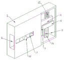
fig. 1 is a schematic perspective view of an embodiment of the present invention;
fig. 2 is a schematic view of a first channel structure according to an embodiment of the present invention;
fig. 3 is a schematic view of a groove structure according to an embodiment of the present invention;
fig. 4 is a schematic structural view of a first L-shaped rotating plate and a second L-shaped rotating plate according to an embodiment of the present invention.
Wherein the figures include the following reference numerals:
the power cord comprises a power cord body 1, a plug 2, a connecting piece 3, a connecting belt 4, a control box 5, a first channel 6, a second channel 7, a groove 8, a fixing rod 9, a first L-shaped rotating plate 10, a second L-shaped rotating plate 11, a first rotating plate 12, a second rotating plate 13, a sliding plate 14, a second spring 15, a first spring 16, a third channel 17 and a fixing column 18.
Detailed Description
The technical solutions in the embodiments of the present invention will be described clearly and completely with reference to the accompanying drawings in the embodiments of the present invention, and it is obvious that the described embodiments are only some embodiments of the present invention, not all embodiments. The following description of at least one exemplary embodiment is merely illustrative in nature and is in no way intended to limit the invention, its application, or uses.
To maintain the following description of the embodiments of the present invention clear and concise, detailed descriptions of well-known functions and components may be omitted.
Referring to fig. 1-4, in the present embodiment, a power line is provided, including: the power cord comprises a power cord body 1, wherein two connecting belts 4 are installed on one side of the power cord body 1, one end of one connecting belt 4 is connected with a control box 5, a first channel 6, a groove 8 and two second channels 7 are formed in the control box 5, the first channel 6 is respectively communicated with the second channels 7 and the groove 8, and a third channel 17 is formed in one side of the first channel 6; a fixed rod 9 is arranged in the groove 8, a first L-shaped rotating plate 10 and a second L-shaped rotating plate 11 are rotatably matched on the peripheral side of the fixed rod 9, a first rotating assembly and a second rotating assembly are respectively arranged on one side of the first L-shaped rotating plate 10 and one side of the second L-shaped rotating plate 11, and a first rotating plate 12 and a second rotating plate 13 are respectively rotatably matched on one side of the first rotating assembly and one side of the second rotating assembly; a first spring 16 is arranged on the lower side of the first L-shaped rotating plate 10, the first spring 16 is connected with the groove 8, a second spring 15 is arranged on the upper side of the second L-shaped rotating plate 11, and the second spring 15 is connected with the groove 8; a sliding plate 14 is slidably fitted in the first channel 6, and a third rotating assembly is mounted on one side of the sliding plate 14 and is rotatably fitted to the first ends of the first rotating plate 12 and the second rotating plate 13, respectively.
The application of one aspect of the embodiment is as follows: when the power line needs to be wound, firstly, the sliding plate 14 is slid, the sliding plate 14 drives the first rotating plate 12 and the second rotating plate 13 to rotate through the third rotating assembly, the first rotating plate 12 drives the first L-shaped rotating plate 10 to rotate on the periphery of the fixed rod 9 through the first rotating assembly, the first spring 16 is compressed, the second rotating plate 13 drives the second L-shaped rotating plate 11 to rotate on the periphery of the fixed rod 9 through the second rotating assembly, the second spring 15 is compressed, then one connecting belt 4 is placed between the first L-shaped rotating plate 10 and the second L-shaped rotating plate 11, the sliding plate 14 is loosened, and the first spring 16 is restored to the initial state, so that the power line is wound.
Through the first rotating plate 12 that sets up, second rotating plate 13, both cooperate mutually, when needs are rolled up the power cord, first rotating plate 12 and second rotating plate 13 drive first L shape rotating plate 10 respectively, second L shape rotating plate 11 rotates, thereby can fix the power cord after the rolling, prevented that the power cord from loosening when not using, and the first channel 6 of setting, let sliding plate 14 slide on the one hand, on the other hand is spacing sliding plate 14 at the gliding in-process of sliding plate 14, the condition of skew has been prevented to sliding plate 14 in gliding in-process from appearing, thereby the stability of sliding plate 14 has been improved.
Plug 2 is installed to the one end of power cord body 1 of this embodiment, and connecting piece 3 is installed to the other end of power cord body 1, and fixed column 18 is installed to one side of sliding plate 14, and fixed column 18 sliding fit is in third channel 17.
The first rotating assembly of the present embodiment includes: and a first rotating rod is arranged between the two first side plates, and the first rotating rod is in rotating fit with the second end of the first rotating plate 12, so that the first rotating plate 12 can be conveniently rotated through the arranged first rotating assembly.
The second rotating assembly of the present embodiment includes: a second rotating rod is arranged between the two second side plates, and the second rotating rod is in rotating fit with the second end of the second rotating plate 13.
The first L-shaped rotating plate 10 of the present embodiment includes: the top plate is connected with the first spring 16, and the third side plate is connected with the two first side plates.
The second L-shaped rotating plate 11 of the present embodiment includes: the bottom plate is connected with the second spring 15, and the fourth side plate is connected with the two second side plates.
The third rotating assembly of the present embodiment includes: and a third rotating rod is arranged between the two fifth side plates and is respectively in rotating fit with the first ends of the first rotating plate 12 and the second rotating plate 13.
The above embodiments may be combined with each other.
It should be noted that the terms "first," "second," and the like in the description and claims of this application and in the drawings described above are used for distinguishing between similar elements and not necessarily for describing a particular sequential or chronological order. It is to be understood that the data so used is interchangeable under appropriate circumstances such that the embodiments of the application described herein are capable of operation in sequences other than those illustrated or described herein.
In the description of the present invention, it should be understood that the orientation or positional relationship indicated by the orientation words such as "front, back, up, down, left, right", "horizontal, vertical, horizontal" and "top, bottom" etc. are usually based on the orientation or positional relationship shown in the drawings, and are only for convenience of description and simplification of description, and in the case of not making a contrary explanation, these orientation words do not indicate and imply that the device or element referred to must have a specific orientation or be constructed and operated in a specific orientation, and therefore, should not be interpreted as limiting the scope of the present invention; the terms "inner and outer" refer to the inner and outer relative to the profile of the respective component itself.
Claims (7)
1. A power cord, comprising: the power line comprises a power line body (1), wherein two connecting bands (4) are installed on one side of the power line body (1), one end of one connecting band (4) is connected with a control box (5), a first channel (6), a groove (8) and two second channels (7) are formed in the control box (5), the first channel (6) is respectively communicated with the second channels (7) and the groove (8), and a third channel (17) is formed in one side of the first channel (6);
a fixing rod (9) is arranged in the groove (8), a first L-shaped rotating plate (10) and a second L-shaped rotating plate (11) are rotationally matched on the peripheral side of the fixing rod (9), a first rotating assembly and a second rotating assembly are respectively arranged on one side of the first L-shaped rotating plate (10) and one side of the second L-shaped rotating plate (11), and a first rotating plate (12) and a second rotating plate (13) are respectively rotationally matched on one side of the first rotating assembly and one side of the second rotating assembly;
a first spring (16) is arranged on the lower side of the first L-shaped rotating plate (10), the first spring (16) is connected with the groove (8), a second spring (15) is arranged on the upper side of the second L-shaped rotating plate (11), and the second spring (15) is connected with the groove (8);
a sliding plate (14) is slidably matched in the first channel (6), a third rotating assembly is installed on one side of the sliding plate (14), and the third rotating assembly is respectively in rotating fit with the first ends of the first rotating plate (12) and the second rotating plate (13).
2. The power cord as claimed in claim 1, wherein the plug (2) is mounted at one end of the power cord body (1), the connecting member (3) is mounted at the other end of the power cord body (1), the fixing post (18) is mounted at one side of the sliding plate (14), and the fixing post (18) is slidably fitted in the third channel (17).
3. The electrical power cord as set forth in claim 1, wherein the first rotating assembly comprises: a first rotating rod is arranged between the two first side plates and is in rotating fit with the second end of the first rotating plate (12).
4. The electrical power cord as set forth in claim 1, wherein the second rotating member comprises: a second rotating rod is arranged between the two second side plates, and the second rotating rod is in rotating fit with the second end of the second rotating plate (13).
5. The electrical power cord as claimed in claim 3, wherein the first L-shaped pivotal plate (10) comprises: the top plate is connected with the first spring (16), and the third side plate is connected with the two first side plates.
6. The electrical power cord as claimed in claim 4, wherein the second L-shaped pivotal plate (11) comprises: the bottom plate is connected with a second spring (15), and the fourth side plate is connected with the two second side plates.
7. The electrical power cord as set forth in claim 4, wherein the third rotating assembly comprises: and a third rotating rod is arranged between the two fifth side plates and is respectively in rotating fit with the first ends of the first rotating plate (12) and the second rotating plate (13).
Priority Applications (1)
| Application Number | Priority Date | Filing Date | Title |
|---|---|---|---|
| CN202021936193.9U CN213025519U (en) | 2020-09-08 | 2020-09-08 | Power line |
Applications Claiming Priority (1)
| Application Number | Priority Date | Filing Date | Title |
|---|---|---|---|
| CN202021936193.9U CN213025519U (en) | 2020-09-08 | 2020-09-08 | Power line |
Publications (1)
| Publication Number | Publication Date |
|---|---|
| CN213025519U true CN213025519U (en) | 2021-04-20 |
Family
ID=75475140
Family Applications (1)
| Application Number | Title | Priority Date | Filing Date |
|---|---|---|---|
| CN202021936193.9U Expired - Fee Related CN213025519U (en) | 2020-09-08 | 2020-09-08 | Power line |
Country Status (1)
| Country | Link |
|---|---|
| CN (1) | CN213025519U (en) |
-
2020
- 2020-09-08 CN CN202021936193.9U patent/CN213025519U/en not_active Expired - Fee Related
Similar Documents
| Publication | Publication Date | Title |
|---|---|---|
| US20060157608A1 (en) | Winding reel device with additional winding unit | |
| JP2020147260A (en) | Cellular phone holder for use in automobile | |
| CN213025519U (en) | Power line | |
| CN204392038U (en) | A kind of stator wiring construction of permanent magnet synchronous motor | |
| CN207719524U (en) | A kind of test manager power cord | |
| CN102377059A (en) | Fastening type power wire and processing method thereof | |
| CN204577715U (en) | A kind of rotary socket | |
| CN217848531U (en) | USB horizontal power adapter | |
| CN201766225U (en) | Extension line | |
| CN210594657U (en) | High-efficient finishing device of data transmission's pencil | |
| CN108233121B (en) | Wiring board with separable socket | |
| CN220291216U (en) | Electric power wiring equipment | |
| CN109922396B (en) | Be used for bluetooth headset extension connecting wire | |
| CN209035351U (en) | A kind of apparatus for leveling coiled for electric wire optical cable | |
| CN216625393U (en) | Combined motor stator | |
| CN214798062U (en) | Portable mobile phone charging wire | |
| CN216662039U (en) | Coiling device for plug wire production | |
| CN203219467U (en) | Earphone convenient for tidying | |
| CN215989522U (en) | Winding fixed double-screen connecting wire | |
| CN211830122U (en) | Fixing equipment for cable | |
| CN206888895U (en) | A kind of band rope sheave limiter applied on rolling blind | |
| CN218732218U (en) | Cable connecting plug storage mechanism | |
| CN217334884U (en) | Wire arranging device for power system | |
| CN219738616U (en) | Cable with self-guiding function | |
| CN219659113U (en) | Switch power line |
Legal Events
| Date | Code | Title | Description |
|---|---|---|---|
| GR01 | Patent grant | ||
| GR01 | Patent grant | ||
| CF01 | Termination of patent right due to non-payment of annual fee |
Granted publication date: 20210420 Termination date: 20210908 |
|
| CF01 | Termination of patent right due to non-payment of annual fee |