CN213024956U - Rotary writing board for teaching - Google Patents
Rotary writing board for teaching Download PDFInfo
- Publication number
- CN213024956U CN213024956U CN202022411583.0U CN202022411583U CN213024956U CN 213024956 U CN213024956 U CN 213024956U CN 202022411583 U CN202022411583 U CN 202022411583U CN 213024956 U CN213024956 U CN 213024956U
- Authority
- CN
- China
- Prior art keywords
- fixed
- writing board
- shaped frame
- clipboard
- columns
- Prior art date
- Legal status (The legal status is an assumption and is not a legal conclusion. Google has not performed a legal analysis and makes no representation as to the accuracy of the status listed.)
- Active
Links
Images


Abstract
The utility model discloses a rotation type clipboard is used in teaching relates to the clipboard field, the utility model discloses a base, the top both sides of base all are fixed with the fixed column, and the top of two fixed columns all runs through there is the support column, and the both sides of two support columns all are fixed with the arc piece, and one side of a plurality of arc pieces all runs through there is first screw rod, and the top of two support columns is fixed with the fixed plate, and electric rotary table is installed at the top of fixed plate. The utility model discloses a set up the fixed plate, electric turntable, the bull stick, the U-shaped frame, bolt and clipboard, when the clipboard is dismantled in needs installation, through placing the clipboard on the U-shaped frame, the bolt that rethread U-shaped frame surface runs through the clipboard to the opposite side of U-shaped frame, thereby it is fixed to lock the clipboard, if need dismantle, same opposite operation can, secondly can be through the function of control electric turntable, make the bull stick drive U-shaped frame rotate, make the clipboard rotate the show angle.
Description
Technical Field
The utility model relates to a clipboard field specifically is a rotation type clipboard is used in teaching.
Background
Teaching is a human-specific talent training activity consisting of teacher's teaching and student's learning. Through the activities, teachers purposefully, planningly and organically guide students to learn and master cultural scientific knowledge and skills, and promote the quality of students to be improved, so that the students become people required by the society.
The prior rotary writing board for teaching is generally supported by a bracket to be fixed, the height is inconvenient to adjust, in the teaching process of a teacher, students and the like need to write and calculate on the desk, the heights of the students and the teacher are inconsistent, the heights of the students and the teacher can not be adjusted according to the use requirements of users, so the fixed supporting writing board is inconvenient for teaching, in addition, in the teaching process, due to the uncontrollable factors of weather, when the sunshine is strongly irradiated in summer, the writing board can cause the phenomenon of light reflection, the angle of the writing board can not be adjusted in a rotating way by a common writing board, and in the teaching process, when the writing range of the writing board is insufficient, the writing board and the bracket need to be moved and adjusted integrally, so the rotary writing board is inconvenient for use in a teaching classroom, secondly, because the writing board and the bracket are mostly integrated, when the writing board is damaged and needs to be replaced, the whole body needs to be replaced, the practicability of the device is greatly reduced, and the resource waste is easily caused.
SUMMERY OF THE UTILITY MODEL
The utility model aims to provide a: the utility model provides a rotation type clipboard is used in teaching in order to solve the clipboard structure and can not adjust its height according to user's user demand and the problem that the clipboard can not rotate the adjustment clipboard angle and the clipboard inconvenient assembly and disassembly, the practicality is low like this.
In order to achieve the above object, the utility model provides a following technical scheme: a rotary writing board for teaching comprises a base, wherein fixed columns are fixed on two sides of the top of the base, supporting columns penetrate through the tops of the two fixed columns, arc-shaped blocks are fixed on two sides of the two supporting columns, a first screw rod penetrates through one side of each arc-shaped block, a fixed plate is fixed on the tops of the two supporting columns, an electric turntable is mounted at the top of the fixed plate, an output end of the electric turntable is connected with a rotating rod, a U-shaped frame is fixed on the top of the rotating rod, a bolt penetrates through the outer surface of the U-shaped frame, a writing board is fixed on the top of the U-shaped frame, a connecting plate is fixed on the bottoms of the two supporting columns, second screw rods penetrate through two sides of the top of the connecting plate, a driving wheel is fixed on the tops of the two second screw rods, a driving belt is sleeved on the outer surface of the driving wheel, and a first supporting plate and a second supporting plate are fixed below one side of the two fixed columns, the motor is installed in the middle of the top of the second supporting plate, the output end of the motor is connected with the rotating shaft, the driven wheel is sleeved on the outer surfaces of the second screw rod and the rotating shaft, and the mounting frames are fixed to two sides of the top of the second supporting plate.
Preferably, the number of the first screw rods is four, and the four first screw rods are in threaded connection with the arc-shaped block.
Preferably, two of the second screws are in threaded connection with the connecting plate.
Preferably, the writing board is clamped with the U-shaped frame, and the bolt is in threaded connection with the U-shaped frame.
Preferably, the two fixing columns are hollow, and one sides of the two fixing columns are provided with openings.
Preferably, the first support plate and the second support plate are parallel to each other, and the lengths of the first support plate and the second support plate are equal.
Preferably, the rotating rod is rotatably connected with the U-shaped frame, and the outer surface of the writing board is smooth.
Compared with the prior art, the beneficial effects of the utility model are that:
1. the utility model is provided with a connecting plate, a first supporting plate, a second screw, a motor, a rotating shaft, a driven wheel, a driving belt and a mounting frame, when the writing board is required to be adjusted in height, the rotating shaft is driven to rotate by the motor operation, so that the rotating shaft drives the second screw to rotate by the driven wheel, and the second screw rotates to drive the driving wheel simultaneously, therefore, the driving belt sleeved on the driving wheel enables the second screw on the other side to rotate synchronously, when the two second screws rotate synchronously, because the second screw is in threaded connection with the connecting plate, the connecting plate can be lifted on the second screw, and because the inside of the fixed column is hollow, and one side is provided with an opening, the lifting of the connecting plate can not affect the device, the connecting plate is lifted to drive the supporting column to lift, when the supporting column, the supporting column can be more stable by screwing the first screw rod, so that the height of the supporting column can be adjusted according to the use requirement of a user, and teaching is facilitated;
2. the utility model discloses a set up the fixed plate, electric turntable, the bull stick, the U-shaped frame, bolt and clipboard, when the clipboard is dismantled in the needs installation, through placing the clipboard on the U-shaped frame, the bolt that rethread U-shaped frame surface runs through the clipboard to the opposite side of U-shaped frame, thereby it is fixed to lock the clipboard, if need dismantle, same opposite operation can, secondly, can be through controlling electric turntable function, make the bull stick drive U-shaped frame and rotate, make the clipboard rotate the show angle, the clipboard is convenient for rotatory to the required angle of adjustment of user like this, the equipment of clipboard is dismantled simultaneously, the practicality of clipboard device is improved.
Drawings
FIG. 1 is a schematic structural view of the present invention;
FIG. 2 is a schematic view of the cross-sectional structure of the fixing column of the present invention;
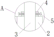
FIG. 3 is an enlarged schematic view of the structure at the position A of the present invention;
fig. 4 is an enlarged schematic view of the position B of the present invention.
In the figure: 1. a base; 2. fixing a column; 3. a support pillar; 4. an arc-shaped block; 5. a first screw; 6. a fixing plate; 7. an electric turntable; 8. a rotating rod; 9. a U-shaped frame; 10. a bolt; 11. a writing board; 12. a connecting plate; 13. a first support plate; 14. a second support plate; 15. a second screw; 16. a motor; 17. a rotating shaft; 18. a driven wheel; 19. a driving wheel; 20. a transmission belt; 21. and (5) installing the frame.
Detailed Description
The technical solutions in the embodiments of the present invention will be described clearly and completely with reference to the accompanying drawings in the embodiments of the present invention, and it is obvious that the described embodiments are only some embodiments of the present invention, not all embodiments. Based on the embodiments in the present invention, all other embodiments obtained by a person skilled in the art without creative work belong to the protection scope of the present invention.
In the description of the present invention, it should be noted that the terms "center", "upper", "lower", "left", "right", "vertical", "horizontal", "inner", "outer", and the like indicate orientations or positional relationships based on the orientations or positional relationships shown in the drawings, and are only for convenience of description and simplification of description, but do not indicate or imply that the device or element referred to must have a specific orientation, be constructed and operated in a specific orientation, and thus, should not be construed as limiting the present invention. Furthermore, the terms "first," "second," and "third" are used for descriptive purposes only and are not to be construed as indicating or implying relative importance. In the description of the present invention, it is to be noted that, unless otherwise explicitly specified or limited, the terms "mounted", "connected" and "disposed" are to be construed broadly, and may be, for example, fixedly connected, detachably connected, or integrally connected; can be mechanically or electrically connected; they may be connected directly or indirectly through intervening media, or they may be interconnected between two elements. The specific meaning of the above terms in the present invention can be understood in specific cases to those skilled in the art. The following describes an embodiment of the present invention according to its overall structure.
Referring to fig. 1-4, a rotary writing board for teaching, comprising a base 1, fixed columns 2, support columns 3, arc-shaped blocks 4, a first screw 5, a fixed plate 6, an electric turntable 7, a rotating rod 8, a U-shaped frame 9, bolts 10, a writing board 11, a connecting plate 12, a first support plate 13, a second support plate 14, a second screw 15, a motor 16, a rotating shaft 17, a driven wheel 18, a driving wheel 19, a driving belt 20 and a mounting frame 21, wherein the fixed columns 2 are fixed on both sides of the top of the base 1, the support columns 3 penetrate through the tops of the two fixed columns 2, the arc-shaped blocks 4 are fixed on both sides of the two support columns 3, the first screw 5 penetrates through one side of each arc-shaped block 4, the fixed plate 6 is fixed on the tops of the two support columns 3, the electric turntable 7 is mounted on the top of the fixed plate 6, the rotating rod 8 is connected to the output end of the electric turntable 7, the U-, bolt 10 has been run through to the surface of U-shaped frame 9, the top of U-shaped frame 9 is fixed with clipboard 11, the bottom of two support columns 3 is fixed with connecting plate 12, second screw rod 15 has all been run through to the top both sides of connecting plate 12, the top of two second screw rods 15 is fixed with drive wheel 19, drive belt 20 has been cup jointed to the surface of drive wheel 19, one side below and one side top of two fixed columns 2 are fixed with first backup pad 13 and second backup pad 14 respectively, install motor 16 in the middle of the top of second backup pad 14, the output of motor 16 is connected with rotation axis 17, driven round of wheel 18 has all been cup jointed to second screw rod 15 and rotation axis 17 surface, the top both sides of second backup pad 14 are fixed with installing frame 21.
Please refer to fig. 1-4, the four first screws 5 are disposed, and the four first screws 5 are in threaded connection with the arc block 4, so as to facilitate the stability of the supporting column 3, and the two second screws 15 are in threaded connection with the connecting plate 12, so as to facilitate the lifting of the connecting plate 12.
Please refer to fig. 1, 2 and 4, the writing board 11 is clamped with the U-shaped frame 9, and the bolt 10 is in threaded connection with the U-shaped frame 9, so as to facilitate the installation and disassembly of the writing board 11, the two fixing columns 2 are hollow, and one side of the two fixing columns 2 is provided with an opening, so as to facilitate the lifting of the supporting column 3.
Please refer to fig. 1-4, the first support plate 13 is parallel to the second support plate 14, and the first support plate 13 is as long as the second support plate 14, which facilitates the stability of the device, the rotating rod 8 is rotatably connected to the U-shaped frame 9, the outer surface of the writing board 11 is smooth, and the writing board 11 is convenient for the user to use.
The working principle is as follows: firstly, when the height of the writing board 11 needs to be adjusted, the motor 16 operates to drive the rotating shaft 17 to rotate, so that the rotating shaft 17 drives the second screw rods 15 to rotate through the driven wheels 18, and the rotation of the second screw rods 15 can drive the driving wheels 19 to rotate at the same time, so that the driving belts 20 sleeved on the driving wheels 19 can drive the second screw rods 15 on the other side to synchronously rotate, when the two second screw rods 15 synchronously rotate, because the second screw rods 15 are in threaded connection with the connecting plate 12, the connecting plate 12 can lift on the second screw rods 15, and because the fixed column 2 is hollow and has an opening on one side, the lifting of the connecting plate 12 can not affect the device, the connecting plate 12 lifts to drive the supporting column 3 to lift, when the supporting column 3 is lifted to a certain position, the supporting column 3 can be more stable by screwing the first screw rods 5, when the writing board 11 needs to be installed, through placing clipboard 11 on U-shaped frame 9, the bolt 10 that the surface of rethread U-shaped frame 9 runs through to the opposite side of U-shaped frame 9 through clipboard 11 to it is fixed to clipboard 11 locking, if need dismantle, same opposite operation can, secondly can be through the operation of control electric turntable 7, makes bull stick 8 drive U-shaped frame 9 rotate, makes clipboard 11 rotate show angle.
It is obvious to a person skilled in the art that the invention is not restricted to details of the above-described exemplary embodiments, but that it can be implemented in other specific forms without departing from the spirit or essential characteristics of the invention. The present embodiments are therefore to be considered in all respects as illustrative and not restrictive, the scope of the invention being indicated by the appended claims rather than by the foregoing description, and all changes which come within the meaning and range of equivalency of the claims are therefore intended to be embraced therein. Any reference sign in a claim should not be construed as limiting the claim concerned.
Claims (7)
1. The utility model provides a rotation type clipboard is used in teaching, includes base (1), its characterized in that: the fixing device is characterized in that fixing columns (2) are fixed on two sides of the top of the base (1), supporting columns (3) penetrate through the tops of the two fixing columns (2), arc-shaped blocks (4) are fixed on two sides of the two supporting columns (3), a first screw rod (5) penetrates through one side of each arc-shaped block (4), a fixing plate (6) is fixed on the tops of the two supporting columns (3), an electric turntable (7) is installed on the top of the fixing plate (6), an output end of the electric turntable (7) is connected with a rotating rod (8), a U-shaped frame (9) is fixed on the top of the rotating rod (8), a bolt (10) penetrates through the outer surface of the U-shaped frame (9), a writing board (11) is fixed on the top of the U-shaped frame (9), a connecting plate (12) is fixed on the bottoms of the two supporting columns (3), and a second screw rod (15) penetrates through two sides of the top of the connecting plate (12), the top of two second screw rods (15) is fixed with drive wheel (19), the surface of drive wheel (19) has cup jointed drive belt (20), and one side below and one side top of two fixed column (2) are fixed with first backup pad (13) and second backup pad (14) respectively, install motor (16) in the middle of the top of second backup pad (14), the output of motor (16) is connected with rotation axis (17), second screw rods (15) and rotation axis (17) surface have all cup jointed from driving wheel (18), the top both sides of second backup pad (14) are fixed with installing frame (21).
2. A rotary teaching writing board according to claim 1, wherein: the first screw rods (5) are four, and the first screw rods (5) are in threaded connection with the arc-shaped blocks (4).
3. A rotary teaching writing board according to claim 1, wherein: the two second screw rods (15) are in threaded connection with the connecting plate (12).
4. A rotary teaching writing board according to claim 1, wherein: the writing board (11) is clamped with the U-shaped frame (9), and the bolt (10) is in threaded connection with the U-shaped frame (9).
5. A rotary teaching writing board according to claim 1, wherein: the two fixing columns (2) are hollow, and one sides of the two fixing columns (2) are provided with openings.
6. A rotary teaching writing board according to claim 1, wherein: the first supporting plate (13) and the second supporting plate (14) are parallel to each other, and the lengths of the first supporting plate (13) and the second supporting plate (14) are equal.
7. A rotary teaching writing board according to claim 1, wherein: the rotating rod (8) is rotatably connected with the U-shaped frame (9), and the outer surface of the writing board (11) is smooth.
Priority Applications (1)
| Application Number | Priority Date | Filing Date | Title |
|---|---|---|---|
| CN202022411583.0U CN213024956U (en) | 2020-10-27 | 2020-10-27 | Rotary writing board for teaching |
Applications Claiming Priority (1)
| Application Number | Priority Date | Filing Date | Title |
|---|---|---|---|
| CN202022411583.0U CN213024956U (en) | 2020-10-27 | 2020-10-27 | Rotary writing board for teaching |
Publications (1)
| Publication Number | Publication Date |
|---|---|
| CN213024956U true CN213024956U (en) | 2021-04-20 |
Family
ID=75481515
Family Applications (1)
| Application Number | Title | Priority Date | Filing Date |
|---|---|---|---|
| CN202022411583.0U Active CN213024956U (en) | 2020-10-27 | 2020-10-27 | Rotary writing board for teaching |
Country Status (1)
| Country | Link |
|---|---|
| CN (1) | CN213024956U (en) |
-
2020
- 2020-10-27 CN CN202022411583.0U patent/CN213024956U/en active Active
Similar Documents
| Publication | Publication Date | Title |
|---|---|---|
| CN213024956U (en) | Rotary writing board for teaching | |
| CN207037978U (en) | A kind of vehicle teaching element fixing device | |
| CN209977651U (en) | Projector supporting device | |
| CN209801017U (en) | Multi-angle audio-visual equipment for meeting room | |
| CN209859308U (en) | Teaching aid for career planning | |
| CN215068658U (en) | Intelligent teaching auxiliary assembly | |
| CN213656205U (en) | Classroom teaching recording device convenient to adjust | |
| CN210721996U (en) | English teaching is with teaching board with adjustable | |
| CN211294179U (en) | Geometry projection device for mathematical education | |
| CN210095045U (en) | Intelligent desk | |
| CN216069393U (en) | Education teaching aid | |
| CN209947191U (en) | Teaching instrument for college English education | |
| CN111477067A (en) | Picture display device for fine arts teaching | |
| CN216647587U (en) | Real standard platform of driving motor | |
| CN214175445U (en) | Management type teaching special frame | |
| CN214068083U (en) | Statistical data column for economic statistics teaching | |
| CN210429005U (en) | Electromechanical engineering circuit presentation device | |
| CN214535302U (en) | Information display rack for teaching management | |
| CN213024985U (en) | Higher mathematic model splicing frame | |
| CN212032612U (en) | Ideological and political publicity moving frame | |
| CN215182609U (en) | College english classroom teaching is with word collection show device | |
| CN220694681U (en) | Business training is with declaring device | |
| CN211403734U (en) | Education project is with show board that has liftable alternative structure | |
| CN220400104U (en) | Multifunctional portable angular momentum demonstration instrument | |
| CN215993104U (en) | Reading rack |
Legal Events
| Date | Code | Title | Description |
|---|---|---|---|
| GR01 | Patent grant | ||
| GR01 | Patent grant |