CN213002183U - Punch forming die for metal structural part - Google Patents
Punch forming die for metal structural part Download PDFInfo
- Publication number
- CN213002183U CN213002183U CN202021542025.1U CN202021542025U CN213002183U CN 213002183 U CN213002183 U CN 213002183U CN 202021542025 U CN202021542025 U CN 202021542025U CN 213002183 U CN213002183 U CN 213002183U
- Authority
- CN
- China
- Prior art keywords
- die
- carrier
- fixedly connected
- mould
- stamping
- Prior art date
- Legal status (The legal status is an assumption and is not a legal conclusion. Google has not performed a legal analysis and makes no representation as to the accuracy of the status listed.)
- Active
Links
Images


Landscapes
- Press Drives And Press Lines (AREA)
Abstract
The utility model discloses a punch forming die for metal structural members, which belongs to the technical field of stamping die application, and comprises a first die carrier, wherein a second die carrier is arranged below the first die carrier, an upper die and a lower die are respectively arranged at one opposite side of the first die carrier and the second die carrier, the interior of the lower die is a cavity, a plurality of telescopic rods are arranged at the bottom end of the inner wall of the lower die, solid rods are arranged at the upper ends of the telescopic rods, the solid rods respectively penetrate through the lower die, and springs are sleeved at the outer sides of the telescopic rods; first mould carrier drives the mould and moves down, and then with sheetmetal stamping forming, because the solid bar is located the outside of bed die before the punching press, when the sheetmetal was by the same shrink downwards of die extrusion time-point pole, potential energy was stored to the spring this moment, and after the mould upwards reseed, the spring bounce-back drove the metal sheet jack-up that solid bar rebound will press close to with the bed die, conveniently collected the metal sheet.
Description
Technical Field
The utility model relates to a stamping die uses technical field, in particular to metal structure stamping forming mould.
Background
The punching die is a special technological equipment for processing material into parts or semi-finished products in cold punching process, called cold punching die, and utilizes the die mounted on the press machine to apply pressure to the material at room temp. to make it produce separation or plastic deformation so as to obtain the required parts.
Traditional stamping die is after accomplishing the punching press to metal material spare, and the material spare after the unable swift completion of punching press is unloaded, needs the workman manually to get the material, and current stamping die is not provided with comparatively convenient garbage collection device for workman's intensity of labour has been increased, and to stamping die's production efficiency greatly reduced.
SUMMERY OF THE UTILITY MODEL
The utility model provides a metallic structure stamping forming die carries out the drawing of patterns through the material spare after the stamping of counterpunch mould is accomplished and gets the material to collect the processing to the material spare slitter edge after the stamping is accomplished, need not the manual material of getting of workman, make the production efficiency to stamping die improve greatly, and then satisfy producer's demand, and reduced workman's intensity of labour, improve device's practicality.
The utility model is realized in such a way, a metal structure stamping forming die comprises a first die carrier, a second die carrier is arranged below the first die carrier, an upper die and a lower die are respectively arranged at one side of the first die carrier opposite to the second die carrier, the lower end surface of the upper die is fixedly connected with a plurality of first convex blocks and first concave blocks which are uniformly distributed, the upper end surface of the lower die is fixedly connected with a plurality of second convex blocks and second concave blocks which are uniformly distributed, the inner part of the lower die is a cavity, the bottom end of the inner wall of the lower die is fixedly connected with a plurality of lower fixing pieces, the upper end surfaces of the lower fixing pieces are fixedly connected with telescopic rods, the upper ends of the telescopic rods are fixedly connected with upper fixing pieces, the upper end surfaces of the upper fixing pieces are fixedly connected with solid rods, and the solid rods respectively penetrate through the second concave blocks and extend to the outer side of the lower die, and springs are sleeved on the outer sides of the telescopic rods.
In order to push away fashioned metal component to the groove that gathers materials, as the utility model discloses a metal structure stamping forming mould is preferred, the rear end face fixed mounting of second mould carrier has the pneumatic cylinder, the output fixed mounting of pneumatic cylinder has the montant, the upper end fixedly connected with horizontal pole of montant, the front end fixedly connected with wave board of horizontal pole, wave board is located between mould and the bed die.
For the convenience collect stamping forming mould, as the utility model discloses a metal structure stamping forming mould is preferred, the outside swing joint of second mould carrier has the groove that gathers materials, the shape of the groove that gathers materials is "U" shape.
In order to fix the position of the collecting groove, as the utility model discloses a metallic structure stamping forming mould is preferred, the lower terminal surface fixedly connected with bottom plate of second mould carrier, two inserted bars of up end fixedly connected with of bottom plate, two the inserted bar is located the left and right sides of second mould carrier respectively, the left and right sides of terminal surface all seted up under the collecting groove with inserted bar assorted slot.
For convenient different last mould and bed die of replacement, conduct the utility model discloses a metal structure stamping forming mould is preferred, go up the equal fixedly connected with dead lever in one side that mould and bed die carried on the back mutually, two the screw has all been seted up to the lateral wall of dead lever.
For the convenience install first mould carrier on the output of punching machine, as the utility model discloses a metal structure stamping forming mould is preferred, the up end fixedly connected with installation pole of first mould carrier.
In order to avoid the wave integrated circuit board in the rear side of bed die, as the utility model discloses a metallic structure stamping forming mould is preferred, the shape phase-match of wave board and second lug and the concave piece of second.
Compared with the prior art, the beneficial effects of the utility model are that:
1. the pre-cut metal sheet is placed between an upper die and a lower die, when a first die carrier drives the upper die to move downwards, the metal sheet is punched and formed, a solid rod is located on the outer side of the lower die before punching, when the metal sheet is extruded by the die, the solid rod also contracts downwards, the spring stores potential energy, the telescopic rod contracts, after the upper die is reset upwards, the spring rebounds to drive the solid rod to move upwards, and then the metal plate close to the lower die is jacked up by the solid rod, so that the metal plate is prevented from being attached to a second convex block and a second concave block, and the metal plate is convenient to collect;
2. when the plurality of solid rods jack up the formed metal plate, the hydraulic cylinder is started to drive the wave plate to move forwards, the wave plate is positioned between the upper die and the lower die, and the formed structural part is pushed out by the wave plate, so that the next stamping work is facilitated;
3. the collecting trough is placed on the bottom plate, the two inserting rods are connected with the two inserting grooves in a clamped mode respectively, the position of the collecting trough is fixed, when the collecting trough is full of structural parts, the collecting trough is moved upwards, the inserting grooves can be separated from the inserting rods, and the collecting trough is convenient to disassemble and install.
Drawings
FIG. 1 is an overall structure diagram of the present invention;
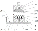
FIG. 2 is an overall sectional view of the present invention;
fig. 3 is a schematic view of the utility model at a;
FIG. 4 is a structural diagram of the wave plate and the hydraulic cylinder of the present invention
In the figure: 1. a first mold carrier; 101. mounting a rod; 2. an upper die; 201. a first bump; 202. a first concave block; 3. a second mold carrier; 4. a lower die; 401. a second bump; 402. a second concave block; 5. a telescopic rod; 501. an upper fixing sheet; 502. a lower fixing sheet; 503. a spring; 504. a solid bar; 6. a material collecting groove; 601. a slot; 7. a base plate; 701. inserting a rod; 8. a wave plate; 801. a cross bar; 802. a vertical rod; 803. a hydraulic cylinder; 9. fixing the rod; 901. and a screw hole.
Detailed Description
In order to make the objects, technical solutions and advantages of the present invention more clearly understood, the present invention is further described in detail below with reference to the accompanying drawings and embodiments. It should be understood that the specific embodiments described herein are merely illustrative of the invention and are not intended to limit the invention.
In the description of the present invention, it is to be understood that the terms "length", "width", "upper", "lower", "front", "rear", "left", "right", "vertical", "horizontal", "top", "bottom", "inner", "outer", and the like indicate orientations or positional relationships based on those shown in the drawings, and are merely for convenience of description and simplicity of description, and do not indicate or imply that the device or element being referred to must have a particular orientation, be constructed and operated in a particular orientation, and thus, should not be construed as limiting the present invention. In addition, in the description of the present invention, "a plurality" means two or more unless specifically limited otherwise.
Referring to fig. 1-4, the present invention provides a technical solution: a punch forming die for a metal structural part comprises a first die carrier 1, a second die carrier 3 is arranged below the first die carrier 1, an upper die 2 and a lower die 4 are respectively installed on one opposite side of the first die carrier 1 and one opposite side of the second die carrier 3, a plurality of first convex blocks 201 and first concave blocks 202 which are uniformly distributed are fixedly connected to the lower end face of the upper die 2, a plurality of second convex blocks 401 and second concave blocks 402 which are uniformly distributed are fixedly connected to the upper end face of the lower die 4, a cavity is formed inside the lower die 4, a plurality of lower fixing plates 502 are fixedly connected to the bottom end of the inner wall of the lower die 4, telescopic rods 5 are fixedly connected to the upper end faces of the lower fixing plates 502, upper fixing plates 501 are fixedly connected to the upper end faces of the upper fixing plates 501, solid rods 504 are respectively connected to the outer sides of the lower die 4 through the second concave blocks 402, the outer sides of the telescopic rods 5 are sleeved with springs 503.
In this embodiment: put the sheetmetal that cuts in advance between mould 2 and bed die 4, drive mould 2 downstream when first mould carrier 1, and then with sheetmetal stamping forming, because solid pole 504 is located the outside of bed die 4 before the punching press, when the sheetmetal is extrudeed by the mould real core rod 504 is same to shrink downwards, potential energy is stored to spring 503 this moment, telescopic link 5 shrink, after last mould 2 upwards resets, spring 503 rebounds and drives solid pole 504 rebound, and then the metal sheet jack-up that will press close to with bed die 4 by solid pole 504, thereby avoid the metal sheet to hug closely with second lug 401 and second concave block 402, conveniently collect the metal sheet.
As the utility model discloses a technical optimization scheme, the rear end face fixed mounting of second mould carrier 3 has pneumatic cylinder 803, and the output fixed mounting of pneumatic cylinder 803 has montant 802, the upper end fixedly connected with horizontal pole 801 of montant 802, the front end fixedly connected with wave board 8 of horizontal pole 801, and wave board 8 is located between mould 2 and the bed die 4.
In this embodiment: when the plurality of solid bars 504 jack up the formed metal plate, the hydraulic cylinder 803 is started to drive the wave plate 8 to move forward, and the wave plate 8 is located between the upper die 2 and the lower die 4, so that the formed structural member is pushed out by the wave plate 8, and the next stamping operation is facilitated.
As a technical optimization scheme of the utility model, the outside swing joint of second mould carrier 3 has a material collecting groove 6, and material collecting groove 6's shape is "U" shape.
In this embodiment: the second die carrier 3 is embedded into the concave part of the U-shaped material collecting groove 6, so that the material collecting groove 6 is positioned around the stamping device, when the wave plate 8 pushes out the formed structural part, the metal sheet falls into the material collecting groove 6, and the effect of conveniently collecting the formed metal structural part is achieved.
As the utility model discloses a technical optimization scheme, second mould carrier 3's lower terminal surface fixedly connected with bottom plate 7, two inserted bars 701 of the up end fixedly connected with of bottom plate 7, two inserted bars 701 are located second mould carrier 3's the left and right sides respectively, the left and right sides of terminal surface all seted up under the material collecting groove 6 with inserted bar 701 assorted slot 601.
In this embodiment: place the groove 6 that gathers materials on bottom plate 7 to make two inserted bar 701 and two slot 601 joint respectively, and then the position of fixed groove 6 that gathers materials, when the groove 6 that gathers materials is full of the structure, rebound groove 6 that gathers materials can make slot 601 and the separation of inserted bar 701, and then convenient dismantlement installation groove 6 that gathers materials.
As a technical optimization scheme of the utility model, go up the equal fixedly connected with dead lever 9 in one side that mould 2 and bed die 4 carried on the back mutually, screw 901 has all been seted up to the lateral wall of two dead levers 9.
In this embodiment: with two dead levers 9 respectively with the inside recess joint of first mould carrier 1 and second mould carrier 3, then use the bolt to run through first mould carrier 1 and second mould carrier 3 to make two bolts run through two screw 901, and then reach the installation and dismantle the effect of last mould 2 and bed die 4.
As a technical optimization scheme of the utility model, the up end fixedly connected with installation pole 101 of first mould carrier 1.
In this embodiment: before punching press metallic structure spare, earlier install installation pole 101 and the output installation of punching machine, restart punching machine drive first mould carrier 1 and last mould 2 downstream to first mould carrier 1 is conveniently installed.
As a technical optimization scheme of the present invention, the shape of the wave plate 8 matches with the shape of the second convex block 401 and the second concave block 402.
In this embodiment: after the metal sheet is punched and formed, due to gravity, the metal sheet is tightly attached to the lower die 4, the solid rod 504 jacks up the metal sheet, and a certain distance is reserved between the metal sheet and the second convex block 401 and the second concave block 402, so that the corrugated plate 8 penetrates through the second convex block 401 and the second concave block 402, and the metal sheet can be pushed into the material collecting groove 6.
The working principle is as follows: before the metal structural member is punched, the mounting rod 101 is mounted with the output end of a punching machine, a pre-cut metal sheet is placed between an upper die 2 and a lower die 4, the punching machine is started to drive a first die carrier 1 and the upper die 2 to move downwards, and then the metal sheet is punched and formed, because a solid rod 504 is positioned on the outer side of the lower die 4 before punching, when the metal sheet is extruded by the dies, the solid rod 504 also contracts downwards, at the moment, a spring 503 stores potential energy, an expansion link 5 contracts, when the upper die 2 resets upwards, the spring 503 rebounds to drive the solid rod 504 to move upwards, and then the solid rod 504 jacks up a metal plate close to the lower die 4, a hydraulic cylinder 803 is started to drive a wave plate 8 to move forwards, and the wave plate 8 is positioned between the upper die 2 and the lower die 4, and then the formed structural member is pushed into a wave collecting groove 6 by the wave collecting groove 8, when the structural member is, the trough 6 is moved upwards to pour out the structure.
The above description is only exemplary of the present invention and should not be construed as limiting the present invention, and any modifications, equivalents and improvements made within the spirit and principles of the present invention are intended to be included within the scope of the present invention.
Claims (7)
1. The utility model provides a metal structure stamping forming mould, includes first mould carrier (1), its characterized in that: a second mold carrier (3) is arranged below the first mold carrier (1), an upper mold (2) and a lower mold (4) are respectively installed on one side, opposite to the first mold carrier (1) and the second mold carrier (3), of the upper mold (2) is fixedly connected with a plurality of first convex blocks (201) and first concave blocks (202) which are uniformly distributed, the upper end face of the lower mold (4) is fixedly connected with a plurality of second convex blocks (401) and second concave blocks (402) which are uniformly distributed, a cavity is formed inside the lower mold (4), a plurality of lower fixing plates (502) are fixedly connected to the bottom end of the inner wall of the lower mold (4), a plurality of upper end faces of the lower fixing plates (502) are fixedly connected with an upper fixing plate (5), a plurality of upper end faces of telescopic rods (5) are fixedly connected with an upper fixing plate (501), and a plurality of upper end faces of the upper fixing plates (501) are fixedly connected with a solid rod (504), the solid rods (504) penetrate through the second concave blocks (402) respectively and extend to the outer side of the lower die (4), and springs (503) are sleeved on the outer sides of the telescopic rods (5).
2. The metal structural member stamping and forming die as claimed in claim 1, wherein: the rear end face of second mould carrier (3) fixed mounting has pneumatic cylinder (803), the output fixed mounting of pneumatic cylinder (803) has montant (802), the upper end fixedly connected with horizontal pole (801) of montant (802), the front end fixedly connected with wave board (8) of horizontal pole (801), wave board (8) are located between last mould (2) and bed die (4).
3. The metal structural member stamping and forming die as claimed in claim 1, wherein: the outer side of the second die carrier (3) is movably connected with a material collecting groove (6), and the material collecting groove (6) is U-shaped.
4. The metal structural member stamping and forming die as claimed in claim 3, wherein: the lower terminal surface fixedly connected with bottom plate (7) of second mould carrier (3), two inserted bar (701) of the up end fixedly connected with of bottom plate (7), two inserted bar (701) are located the left and right sides of second mould carrier (3) respectively, the left and right sides of terminal surface all seted up with inserted bar (701) assorted slot (601) under material collecting tank (6).
5. The metal structural member stamping and forming die as claimed in claim 1, wherein: the upper die (2) and the lower die (4) are fixedly connected with fixing rods (9) on the opposite sides, and screw holes (901) are formed in the outer side walls of the two fixing rods (9).
6. The metal structural member stamping and forming die as claimed in claim 1, wherein: the upper end face of the first die carrier (1) is fixedly connected with a mounting rod (101).
7. The metal structural member stamping and forming die as claimed in claim 2, wherein: the shape of the wave plate (8) is matched with the shapes of the second convex block (401) and the second concave block (402).
Priority Applications (1)
| Application Number | Priority Date | Filing Date | Title |
|---|---|---|---|
| CN202021542025.1U CN213002183U (en) | 2020-07-30 | 2020-07-30 | Punch forming die for metal structural part |
Applications Claiming Priority (1)
| Application Number | Priority Date | Filing Date | Title |
|---|---|---|---|
| CN202021542025.1U CN213002183U (en) | 2020-07-30 | 2020-07-30 | Punch forming die for metal structural part |
Publications (1)
| Publication Number | Publication Date |
|---|---|
| CN213002183U true CN213002183U (en) | 2021-04-20 |
Family
ID=75460360
Family Applications (1)
| Application Number | Title | Priority Date | Filing Date |
|---|---|---|---|
| CN202021542025.1U Active CN213002183U (en) | 2020-07-30 | 2020-07-30 | Punch forming die for metal structural part |
Country Status (1)
| Country | Link |
|---|---|
| CN (1) | CN213002183U (en) |
Cited By (5)
| Publication number | Priority date | Publication date | Assignee | Title |
|---|---|---|---|---|
| CN113953345A (en) * | 2021-10-19 | 2022-01-21 | 南京金城三国机械电子有限公司 | Cold extrusion tool and assembly method thereof |
| CN114247791A (en) * | 2021-12-27 | 2022-03-29 | 昆山市易密斯电子材料有限公司 | Multi-section shaper for beryllium copper reed |
| CN115008669A (en) * | 2022-05-23 | 2022-09-06 | 如皋易塑复合新材料有限公司 | Corrugated board compression molding equipment and compression molding process thereof |
| CN115446175A (en) * | 2022-08-26 | 2022-12-09 | 楚能新能源股份有限公司 | Anti-manufacturing installation that prevents of laser welding sheetmetal |
| CN116133225A (en) * | 2022-09-08 | 2023-05-16 | 中国科学院近代物理研究所 | Manufacturing method of ultrathin-wall metal lining vacuum chamber |
-
2020
- 2020-07-30 CN CN202021542025.1U patent/CN213002183U/en active Active
Cited By (6)
| Publication number | Priority date | Publication date | Assignee | Title |
|---|---|---|---|---|
| CN113953345A (en) * | 2021-10-19 | 2022-01-21 | 南京金城三国机械电子有限公司 | Cold extrusion tool and assembly method thereof |
| CN114247791A (en) * | 2021-12-27 | 2022-03-29 | 昆山市易密斯电子材料有限公司 | Multi-section shaper for beryllium copper reed |
| CN115008669A (en) * | 2022-05-23 | 2022-09-06 | 如皋易塑复合新材料有限公司 | Corrugated board compression molding equipment and compression molding process thereof |
| CN115446175A (en) * | 2022-08-26 | 2022-12-09 | 楚能新能源股份有限公司 | Anti-manufacturing installation that prevents of laser welding sheetmetal |
| CN116133225A (en) * | 2022-09-08 | 2023-05-16 | 中国科学院近代物理研究所 | Manufacturing method of ultrathin-wall metal lining vacuum chamber |
| CN116133225B (en) * | 2022-09-08 | 2023-08-04 | 中国科学院近代物理研究所 | Manufacturing method of ultrathin-wall metal lining vacuum chamber |
Similar Documents
| Publication | Publication Date | Title |
|---|---|---|
| CN213002183U (en) | Punch forming die for metal structural part | |
| CN202199682U (en) | Lower reinforced plate mould for pedal assembly for miniature coach | |
| CN217290036U (en) | Mould is used in production of cell-phone shield cover | |
| CN216226484U (en) | Stamping die is used in sheet metal processing | |
| CN215697466U (en) | Automatic punch forming device for metal product production | |
| CN214108509U (en) | Automatic panel stamping die of material loading | |
| CN214820095U (en) | Plastic casing mold processing | |
| CN213317220U (en) | Formed sleeve stamping die | |
| CN210702008U (en) | Radiator main fin cut-out press | |
| CN210702102U (en) | Stamping forming die for main fins of radiators | |
| CN210023490U (en) | Plate forming device | |
| CN210702068U (en) | Stamping die for inner door plate of crane driver door | |
| CN209021055U (en) | A kind of stamping die for saving material | |
| CN220574494U (en) | Tank wagon wave shield shaping processingequipment | |
| CN219817800U (en) | Automobile sheet metal stamping equipment | |
| CN212822131U (en) | Punching device for stamping part | |
| CN218361601U (en) | Refrigerator hinge stamping device that bends | |
| CN214639641U (en) | A high-efficient stamping die for production of data machine case shell | |
| CN213104026U (en) | Punch structure of numerical control powder metallurgy die | |
| CN214866569U (en) | Fixed bolster cut-out press | |
| CN217665804U (en) | Sheet metal stamping composite die | |
| CN215471641U (en) | Rubber press takes off material and collects mechanism | |
| CN219664918U (en) | Clamp stamping die | |
| CN217369952U (en) | Intelligent stamping equipment for plates | |
| CN219685877U (en) | Punching and blanking device for automobile sheet metal parts |
Legal Events
| Date | Code | Title | Description |
|---|---|---|---|
| GR01 | Patent grant | ||
| GR01 | Patent grant |