CN213002134U - Blanking-punching composite die for automobile rear axle oil pipe support - Google Patents
Blanking-punching composite die for automobile rear axle oil pipe support Download PDFInfo
- Publication number
- CN213002134U CN213002134U CN202021893944.3U CN202021893944U CN213002134U CN 213002134 U CN213002134 U CN 213002134U CN 202021893944 U CN202021893944 U CN 202021893944U CN 213002134 U CN213002134 U CN 213002134U
- Authority
- CN
- China
- Prior art keywords
- die
- blanking
- plate
- punching
- corrector
- Prior art date
- Legal status (The legal status is an assumption and is not a legal conclusion. Google has not performed a legal analysis and makes no representation as to the accuracy of the status listed.)
- Active
Links
Images


Abstract
The utility model relates to a car rear axle oil pipe support blanking-compound mould that punches a hole, including last mould part and lower mould part, go up the mould part and include: the punching die comprises a die handle, an upper die plate, a beating rod, a beating block, a gasket, an upper base plate, a beating rod, an upper fixing plate, a guide sleeve, a die corrector, a blanking female die, a beating device and a punching male die; the lower die part includes: the device comprises a stripper plate, a compound die, a stop pin, a guide pillar, a lower fixing plate, a lower padding plate, a stripper rubber and a lower die plate. The upper section of the die corrector is in interference fit with the middle fixing cavity of the upper backing plate, the lower section of the die corrector is in interference fit with the middle blanking edge cavity of the blanking female die, and the fixing height is 8mm, so that the position degree of the punching male die and the blanking female die of the upper die part and the uniformity of the punching gap between the punching male die and the compound die are automatically guaranteed by the die corrector instead of manual control of fitter assembly.
Description
Technical Field
The utility model belongs to the mechanical equipment field relates to a make mould for oil pipe support, in particular to car rear axle oil pipe support blanking-compound mould that punches a hole.
Background
The oil pipe support is one of essential accessories for fixing and supporting various oil pipes and wiring harnesses on the rear axle of the automobile, and directly influences the layout, installation and fixation of the various oil pipes and wiring harnesses. The oil pipe support is processed by four working procedures according to the traditional production mode, and the process flow is as follows: blanking → punching (i.e. because the shape of the product is complicated and has a plurality of holes) → bending, so as to meet the design requirements of the product. Because the oil pipe support is produced in large batches, and the products in the punching process are difficult to position, take and place (namely, because the appearance and the shape of the products are complex), the production efficiency is lower and the production time is longer by using the traditional production process. And current traditional press die structure is guide pin bushing, guide pillar direct mount on upper and lower template, and the mould clearance is controlled by pincers worker's manual skill completely, and the mould preparation precision is difficult to guarantee like this, and the product blanking, the burr height of punching a hole often is out of tolerance. The utility model discloses just based on the optimizability consideration that production technology exists among the prior art, the design produces a new oil pipe support blanking-compound mould that punches a hole, improves production efficiency, guarantees product quality, just seems very important.
SUMMERY OF THE UTILITY MODEL
The utility model aims at solving the defects in the prior art and providing a blanking-punching composite die for an automobile rear axle oil pipe support.
In order to realize the purpose, the utility model discloses a technical scheme as follows:
a blanking-punching composite die for an oil pipe support of an automobile rear axle comprises an upper die part and a lower die part, wherein the upper die part comprises: the punching die comprises a die handle, an upper die plate, a beating rod, a beating block, a gasket, an upper base plate, a beating rod, an upper fixing plate, a guide sleeve, a die corrector, a blanking female die, a beating device and a punching male die;
the lower die part includes: the device comprises a stripper plate, a compound die, a stop pin, a guide pillar, a lower fixing plate, a lower base plate, a stripper rubber and a lower die plate;
the guide sleeve is assembled in guide sleeve holes at two sides of the upper fixing plate in an interference fit manner, two punching male dies are assembled in male die fixing holes corresponding to the die corrector in an interference fit manner, the blanking female die is assembled in a middle fixing cavity of the upper fixing plate in an interference fit manner, the upper end face of the blanking female die is connected with the upper backing plate through a bolt, the upper end part of the die corrector is assembled in a fixing cavity of the upper backing plate in an interference fit manner, the lower end part of the die corrector is assembled in a middle blanking edge cavity of the blanking female die in an interference fit manner, the upper end face of the die corrector is connected with a gasket through a bolt, the knockout is placed in a cavity formed by the blanking female die and the punching male die in a clearance fit manner, the upper end face of the knockout is movably connected with the die corrector and the gasket through a knockout rod, the knockout is directly placed in a middle knockout cavity of the upper die plate in a clearance fit manner, and the, the die shank is directly placed in a middle die shank cavity of the upper die plate through clearance fit and is connected with the upper die plate through a bolt, and the knock-off rod is directly placed in a knock-off rod hole of the die shank through clearance fit;
the guide pillar passes through interference fit dress in the guide pillar hole on bottom plate both sides, the compound die passes through interference fit dress in the middle fixed cavity of bottom plate, and the lower terminal surface passes through the bolt and is connected with the bottom plate, the bottom plate passes through the bolt and the locating pin is connected with the bottom plate, three striker pins pass through interference fit dress in the fixed orifices that the stripper respectively corresponds, the stripper passes guide pillar and compound die through clearance fit, and through the bolt of unloading and the rubber of unloading, bottom plate, lower bolster swing joint.
Furthermore, the upper section of the die corrector is in interference fit with the middle fixing cavity of the upper backing plate, the lower section of the die corrector is in interference fit with the middle blanking edge cavity of the blanking female die, the fixing height is 8mm, and the position degree of the punching male die and the blanking female die of the upper die part and the uniformity of the punching gap between the punching male die and the compound die are controlled by the die corrector.
Furthermore, the guide sleeve and the blanking female die are fixed in the upper fixing plate, the guide pillar and the compound die are fixed in the lower fixing plate, and the double-side gap between the guide pillar and the guide sleeve is 0.08-0.10 mm.
Furthermore, the blanking female die is of an embedded structure and is fixed in the upper fixing plate.
Further, the lower fixing plate is of a step structure.
Furthermore, four phi 42 holes for placing the discharging rubber are formed in the lower fixing plate and the lower backing plate.
Furthermore, the lower end face of the die handle is provided with a yielding groove corresponding to the hitting block, and the die is integrally installed on a 63T press machine.
The utility model has the advantages that: 1. the upper section of the die corrector is in interference fit with the middle fixing cavity of the upper backing plate, the lower section of the die corrector is in interference fit with the middle blanking blade-shaped cavity of the blanking female die, and the fixing height is 8mm, so that the position degree of the punching male die and the blanking female die of the upper die part and the uniformity of the punching gap between the punching male die and the compound die are automatically ensured by the die corrector without manual control of fitter assembly;
2. the guide sleeve and the blanking female die are fixed in the upper fixing plate, the guide pillar and the compound die are fixed in the lower fixing plate, and the double-sided gap between the guide pillar and the guide sleeve is 0.08-0.10 mm, so that the uniformity of the die gap is not controlled by manual skill of a fitter but is ensured by the machining precision of a machine tool, and the die precision is improved.
The blanking female die is of an embedded structure and is fixed in the upper fixing plate, so that the material cost of the blanking female die can be saved, and the precision of the die cannot be influenced when the quick-wear part of the blanking female die is replaced by the die (namely, the guide sleeve and the upper fixing plate do not need to be replaced);
3. the lower fixing plate is of a step structure, so that the fixed height of the compound die is as high as possible, the strength of the compound die can be improved, and the service life of the die is prolonged;
4. the lower fixing plate and the lower backing plate are respectively provided with four holes phi 42 for placing the discharging rubber, so that the height of the compound die can be reduced as much as possible, the strength of the compound die is improved, the discharging rubber has enough discharging force, and the closing height of the die can be reduced.
Drawings
Fig. 1 is a schematic structural view of the present invention;
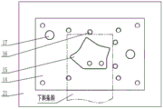
FIG. 2 is a schematic top view of the lower mold part of the present invention;
fig. 3 is a schematic view of the oil pipe support workpiece processed by the utility model.
Detailed Description
As shown in fig. 1 to 3, a blanking-punching composite die for an oil pipe bracket of a rear axle of an automobile comprises an upper die part and a lower die part of the die, wherein the upper die part of the die comprises: the punching die comprises a die shank 1, an upper die plate 2, a striking rod 3, a striking block 4, a gasket 5, an upper backing plate 6, a striking rod 7, an upper fixing plate 8, a guide sleeve 9, a die corrector 10, a blanking female die 11, a striking device 12 and a punching male die 13;
the lower die portion of the die includes: the device comprises a stripper plate 14, a compound die 15, a striker pin 16, a guide post 17, a lower fixing plate 18, a lower backing plate 19, a stripper rubber 20 and a lower die plate 21.
The guide sleeve 9 is arranged in guide sleeve holes at two sides of an upper fixing plate 8 in an interference fit manner, two punching male dies 13 are arranged in male die fixing holes corresponding to the die correction device 10 in an interference fit manner, the blanking female die 11 is arranged in a middle fixing cavity of the upper fixing plate 8 in an interference fit manner, the upper end face of the blanking female die 11 is connected with the upper backing plate 6 through bolts, the upper end part of the die correction device 10 is arranged in a fixing cavity of the upper backing plate 6 in an interference fit manner, the lower end part of the die correction device 10 is arranged in a middle blanking edge cavity of the blanking female die 11 in an interference fit manner, the upper end face of the die correction device 10 is connected with the gasket 5 through bolts, the material beating device 12 is arranged in a cavity formed by the blanking female die 11 and the punching male dies 13 in a clearance fit manner, the upper end face of the material beating device is movably connected with the die correction device 10 and the gasket 5 through a beating rod 7, the beating block 4 is directly arranged, The gasket 5 and the upper backing plate 6 are connected with an upper fixing plate 8 through bolts and positioning pins, the die shank 1 is directly placed in a middle die shank cavity of the upper die plate 2 through clearance fit and is connected with the upper die plate 2 through bolts, and the striking rod 3 is directly placed in a striking rod hole of the die shank 1 through clearance fit; the guide post 17 is arranged in guide post holes at two sides of a lower fixing plate 18 in an interference fit manner, the compound die 15 is arranged in a middle fixing cavity of the lower fixing plate 18 in the interference fit manner, the lower end face of the compound die is connected with the lower backing plate 19 through a bolt, the lower backing plate 21 and the lower backing plate 19 are connected with the lower fixing plate 18 through bolts and positioning pins, three material blocking pins 16 are arranged in corresponding fixing holes of a discharging plate 14 in the interference fit manner, the discharging plate 14 penetrates through the guide post 17 and the compound die 15 in a clearance fit manner, and is movably connected with the discharging rubber 20, the lower fixing plate 18, the lower backing plate 19 and the lower backing plate 21 through the discharging bolts.
Furthermore, the upper section of the die corrector 10 is in interference fit with the middle fixing cavity of the upper backing plate 6, the lower section of the die corrector 10 is in interference fit with the middle blanking edge cavity of the blanking female die 11, and the fixing height is 8mm, so that the position degree of the punching male die 13 and the blanking female die 11 of the upper die part and the uniformity of the punching gap between the punching male die 13 and the compound die 15 are automatically ensured by the die corrector 10 instead of manual control of fitter assembly.
The guide sleeve 9 and the blanking female die 11 are both fixed in the upper fixing plate 8, the guide pillar 17 and the compound die 15 are both fixed in the lower fixing plate 18, and the double-sided gap between the guide pillar 17 and the guide sleeve 9 is 0.08-0.10 mm, so that the uniformity of the die gap is not controlled by the manual skill of a bench worker, but is ensured by the machining precision of a machine tool, and the die precision is improved.
In addition, the blanking female die 11 is of an embedded structure and is fixed in the upper fixing plate 8, so that the material cost of the blanking female die 11 can be saved, and the precision of the die cannot be influenced when the quick-wear part of the blanking female die 11 is replaced by the die (namely, the guide sleeve 9 and the upper fixing plate 8 do not need to be replaced).
The lower fixing plate 18 has a stepped structure, so that the fixed height of the compound die 15 is as high as possible, thereby improving the strength of the compound die 15 and prolonging the service life of the die.
Furthermore, the lower fixing plate 18 and the lower backing plate 19 are respectively provided with four holes phi 42 for placing the discharging rubber 20, so that the height of the compound die 15 can be reduced as much as possible, the strength of the compound die 15 is improved, the discharging rubber 20 has enough discharging force, and the closing height of the die can be reduced.
The lower end face of the die shank 1 is provided with a yielding groove for the hitting block 4, so that the closing height of the die can be reduced, and the die can be installed on a 63T press machine for manufacturing.
The blanking-punching composite die for the automobile rear axle oil pipe support comprises the following steps of:
step 1: the blanking-punching composite die for the automobile rear axle oil pipe support is arranged on a 63T press;
step 2: placing the oil pipe support strip material subjected to the blanking process above the stripper plate 14, and enabling the front end face of the oil pipe support strip material to be close to the material blocking pin 16 positioned at the front part and the right end face to be close to the material blocking pin 16 guided to the right side;
and 3, step 3: starting a press machine, enabling an upper template 2 to move downwards along with an upper workbench of a machine tool, firstly pressing a strip material by a blanking female die 11, an upper fixing plate 8 and a discharging plate 14 under the pressure action of a discharging rubber 20, and then continuing to move downwards along with the blanking female die 11 and a punching male die 13 to complete a workpiece blanking process and a punching process with a compound die 15;
and 4, step 4: after a workpiece is subjected to blanking and punching processing, an upper sliding block on a press machine drives an upper die part of a die to return, then a material beating mechanism on an upper workbench of the press machine drives a beating rod 3 to slide downwards, the beating rod 3 drives a beating block 4 to slide downwards, the beating block 4 drives a beating rod 7 to slide downwards, the beating rod 7 drives a material beating device 12 to slide downwards to beat out the workpiece, a discharging plate 14 unloads falling material waste under the action of a discharging rubber 20, and the punching material waste directly leaks from a lower die and the lower workbench of a machine tool;
and 5, step 5: using an oil pipe bracket strip to transversely shift the punched workpiece into a material box from the left side in the falling process;
and 6, step 6: and (5) repeating the operations from the step 2 to the step 5 to manufacture the lower workpiece.
After the oil pipe support uses the blanking-punching composite die, relevant sizes of blanking, punching and the like are in a tolerance range. The two traditional processes are optimized into one process, the production efficiency is improved by 78%, the development cost of the die in one set of process is saved, the die adopts a guide pillar and a guide sleeve which automatically correct the gap of the die, the die correcting device is additionally arranged on the upper die part, and the lower fixing plate is additionally provided with a step type structure and the like, so that the service life of the die is prolonged by 11 times, the production cost is reduced, and the quality of workpieces is stable.
The foregoing shows and describes the general principles, essential features, and advantages of the invention. It will be understood by those skilled in the art that the present invention is not limited to the above embodiments, and that the principles of the present invention may be applied to any other embodiment without departing from the spirit and scope of the present invention. The scope of the invention is defined by the appended claims and equivalents thereof.
Claims (7)
1. The blanking-punching composite die for the oil pipe support of the rear axle of the automobile comprises an upper die part and a lower die part, and is characterized in that the upper die part comprises: the punching die comprises a die handle (1), an upper die plate (2), a striking rod (3), a striking block (4), a gasket (5), an upper backing plate (6), a striking rod (7), an upper fixing plate (8), a guide sleeve (9), a die corrector (10), a blanking female die (11), a striking device (12) and a punching male die (13); the lower die part includes: the device comprises a stripper plate (14), a compound die (15), a stop pin (16), a guide post (17), a lower fixing plate (18), a lower backing plate (19), a stripper rubber (20) and a lower template (21); the guide sleeve (9) is arranged in guide sleeve holes at two sides of an upper fixing plate (8) in an interference fit manner, two punching male dies (13) are arranged in male die fixing holes corresponding to the die corrector (10) in an interference fit manner, a blanking female die (11) is arranged in a middle fixing cavity of the upper fixing plate (8) in an interference fit manner, the upper end face of the blanking female die is connected with an upper backing plate (6) through a bolt, the upper end part of the die corrector (10) is arranged in a fixing cavity of the upper backing plate (6) in an interference fit manner, the lower end part of the die corrector (10) is arranged in a middle blanking blade-edge cavity of the blanking female die (11) in an interference fit manner, the upper end face of the die corrector is connected with a gasket (5) through a bolt, a material beating device (12) is arranged in a cavity formed by the blanking female die (11) and the punching male dies (13) in a clearance fit manner, and the upper end face of the die corrector is movably connected with the die corrector (, the hitting block (4) is directly placed in a middle hitting block cavity of the upper template (2) through clearance fit, the upper template (2), the gasket (5) and the upper backing plate (6) are connected with the upper fixing plate (8) through bolts and positioning pins, the die shank (1) is directly placed in a middle die shank cavity of the upper template (2) through clearance fit and is connected with the upper template (2) through bolts, and the hitting rod (3) is directly placed in a hitting rod hole of the die shank (1) through clearance fit; guide posts (17) are arranged in guide post holes on two sides of a lower fixing plate (18) in an interference fit manner, a composite die (15) is arranged in a middle fixing cavity of the lower fixing plate (18) in the interference fit manner, the lower end face of the composite die is connected with a lower cushion plate (19) through bolts, the lower cushion plate (21) and the lower cushion plate (19) are connected with the lower fixing plate (18) through bolts and positioning pins, three material blocking pins (16) are arranged in fixing holes corresponding to the discharging plate (14) in the interference fit manner, the discharging plate (14) penetrates through the guide posts (17) and the composite die (15) in a clearance fit manner, and is movably connected with the discharging rubber (20), the lower fixing plate (18), the lower cushion plate (19) and the lower cushion plate (21) through discharging bolts.
2. The blanking-punching composite die for the oil pipe bracket of the rear axle of the automobile according to claim 1, wherein the upper section of the die corrector (10) is in interference fit with the middle fixing cavity of the upper backing plate (6), the lower section of the die corrector (10) is in interference fit with the middle blanking edge cavity of the blanking female die (11), the fixed height is 8mm, and the position degree of the punching male die (13) of the upper die part and the blanking female die (11) and the uniformity of the punching gap between the punching male die (13) and the composite die (15) are controlled by the die corrector (10).
3. The blanking-punching compound die for the oil pipe bracket of the rear axle of the automobile as claimed in claim 2, wherein the guide sleeve (9) and the blanking female die (11) are both fixed in the upper fixing plate (8), the guide pillar (17) and the compound die (15) are both fixed in the lower fixing plate (18), and the double-sided gap between the guide pillar (17) and the guide sleeve (9) is 0.08-0.10 mm.
4. The blanking-punching composite die for the oil pipe support of the rear axle of the automobile as claimed in claim 2, wherein the blanking female die (11) is of an embedded structure and is fixed in the upper fixing plate (8).
5. The blanking-punching composite die for the oil pipe support of the rear axle of the automobile as claimed in claim 2, wherein the lower fixing plate (18) is of a stepped structure.
6. The blanking-punching composite die for the oil pipe bracket of the rear axle of the automobile as claimed in claim 2, wherein the lower fixing plate (18) and the lower backing plate (19) are provided with four holes phi 42 for placing the discharging rubber (20).
7. The blanking-punching composite die for the oil pipe bracket of the rear axle of the automobile according to claim 2, wherein the lower end surface of the die shank (1) is provided with a yielding groove corresponding to the hitting block (4), and the die is integrally installed on a 63T press.
Priority Applications (1)
| Application Number | Priority Date | Filing Date | Title |
|---|---|---|---|
| CN202021893944.3U CN213002134U (en) | 2020-09-03 | 2020-09-03 | Blanking-punching composite die for automobile rear axle oil pipe support |
Applications Claiming Priority (1)
| Application Number | Priority Date | Filing Date | Title |
|---|---|---|---|
| CN202021893944.3U CN213002134U (en) | 2020-09-03 | 2020-09-03 | Blanking-punching composite die for automobile rear axle oil pipe support |
Publications (1)
| Publication Number | Publication Date |
|---|---|
| CN213002134U true CN213002134U (en) | 2021-04-20 |
Family
ID=75474205
Family Applications (1)
| Application Number | Title | Priority Date | Filing Date |
|---|---|---|---|
| CN202021893944.3U Active CN213002134U (en) | 2020-09-03 | 2020-09-03 | Blanking-punching composite die for automobile rear axle oil pipe support |
Country Status (1)
| Country | Link |
|---|---|
| CN (1) | CN213002134U (en) |
Cited By (1)
| Publication number | Priority date | Publication date | Assignee | Title |
|---|---|---|---|---|
| CN114273523A (en) * | 2021-12-20 | 2022-04-05 | 江西江铃底盘股份有限公司 | Blanking-punching composite die for automobile rear axle wiring harness support and machining process of blanking-punching composite die |
-
2020
- 2020-09-03 CN CN202021893944.3U patent/CN213002134U/en active Active
Cited By (1)
| Publication number | Priority date | Publication date | Assignee | Title |
|---|---|---|---|---|
| CN114273523A (en) * | 2021-12-20 | 2022-04-05 | 江西江铃底盘股份有限公司 | Blanking-punching composite die for automobile rear axle wiring harness support and machining process of blanking-punching composite die |
Similar Documents
| Publication | Publication Date | Title |
|---|---|---|
| CN103894515A (en) | Manufacturing technology, molding die and punching-cutting die for automotive rear axle wiring harness supports | |
| CN213002134U (en) | Blanking-punching composite die for automobile rear axle oil pipe support | |
| CN101722237A (en) | Automotive wiring harness die | |
| CN109248956B (en) | Floating cantilever type punching die and punching process for automobile driving rear axle brake support | |
| CN210877129U (en) | One-time simultaneous blanking-punching manufacturing two-piece composite die for automobile rear axle refueling plug seat | |
| CN201644616U (en) | Compound die for blanking and punching of automobile plate spring clips | |
| CN209363412U (en) | A kind of stamping system of battery mounting bracket | |
| CN111097837A (en) | Reverse punching die for circular tube part | |
| CN206882566U (en) | A kind of car drive front axle main reducing gear oil baffle punching and blanking progressive die | |
| CN218693176U (en) | Blanking-tooth-shaped hole punching-circular hole punching composite die for automobile rear axle three-way support | |
| CN204975026U (en) | Multidirectional bending's car sheet metal component upgrades mould | |
| CN112676439B (en) | Punching and welding integrated clamping device | |
| CN211437772U (en) | Combined die | |
| CN212168712U (en) | Fast switching mold | |
| CN210358842U (en) | Front door mounting metal support die and front door mounting metal support thereof | |
| CN210131978U (en) | Side wall flanging die for chassis rear plate | |
| CN207325712U (en) | A kind of blanking two pieces blanking die of Rear Axle Steel Plate seat support | |
| CN206981569U (en) | One kind adjustment limiting plate Blanking Punching Compound Die | |
| CN211489292U (en) | Forming die for automobile rear axle oil baffle cover | |
| CN215431112U (en) | Stamping integrated forming die | |
| CN114273523A (en) | Blanking-punching composite die for automobile rear axle wiring harness support and machining process of blanking-punching composite die | |
| CN205571171U (en) | Baffle blanking modulus of continuity that punches a hole before car | |
| CN219171518U (en) | Injection mold male mold processing improvement structure of automobile ornament | |
| CN213002205U (en) | One-time bending-bending composite die for automobile front axle support | |
| CN218925876U (en) | Special-shaped connecting plate blanking device |
Legal Events
| Date | Code | Title | Description |
|---|---|---|---|
| GR01 | Patent grant | ||
| GR01 | Patent grant |