CN212986535U - Wisdom security protection watch-dog - Google Patents
Wisdom security protection watch-dog Download PDFInfo
- Publication number
- CN212986535U CN212986535U CN202021680351.9U CN202021680351U CN212986535U CN 212986535 U CN212986535 U CN 212986535U CN 202021680351 U CN202021680351 U CN 202021680351U CN 212986535 U CN212986535 U CN 212986535U
- Authority
- CN
- China
- Prior art keywords
- fixedly connected
- sealing gasket
- step motor
- shell
- solar cell
- Prior art date
- Legal status (The legal status is an assumption and is not a legal conclusion. Google has not performed a legal analysis and makes no representation as to the accuracy of the status listed.)
- Active
Links
Images


Classifications
-
- Y—GENERAL TAGGING OF NEW TECHNOLOGICAL DEVELOPMENTS; GENERAL TAGGING OF CROSS-SECTIONAL TECHNOLOGIES SPANNING OVER SEVERAL SECTIONS OF THE IPC; TECHNICAL SUBJECTS COVERED BY FORMER USPC CROSS-REFERENCE ART COLLECTIONS [XRACs] AND DIGESTS
- Y02—TECHNOLOGIES OR APPLICATIONS FOR MITIGATION OR ADAPTATION AGAINST CLIMATE CHANGE
- Y02E—REDUCTION OF GREENHOUSE GAS [GHG] EMISSIONS, RELATED TO ENERGY GENERATION, TRANSMISSION OR DISTRIBUTION
- Y02E10/00—Energy generation through renewable energy sources
- Y02E10/50—Photovoltaic [PV] energy
Abstract
The utility model discloses a wisdom security protection watch-dog, including the holding surface, the inside of holding surface is inlayed and is had the concrete piece, the upper end of concrete piece is provided with the fixed plate, be provided with a plurality of fixing bolt between fixed plate and the concrete piece, the vertical fixedly connected with stay tube in upper end of fixed plate. The utility model discloses in, the solar cell panel of setting can charge to the lithium cell, first step motor can drive the carousel and rotate, thereby it rotates to drive solar cell panel, make solar cell panel can face sun exposure's direction, and the rotation range of first step motor is in the within range of 0-360 degrees, camera in the monitoring subassembly can carry out face identification, night vision, functions such as dynamic tracking, the camera can rotate under the drive of second step motor, and the rotation range of second step motor is for controlling the skew at the within range of 270 degrees, make the monitoring range of two cameras can have certain coincidence, reduce the existence of keeping watch on the blind area.
Description
Technical Field
The utility model relates to a supervisory equipment technical field especially relates to a wisdom security protection watch-dog.
Background
The security monitoring system is an independent and complete system which is formed by transmitting video signals in a closed loop by using optical fibers, coaxial cables or microwaves, and shooting, image display and recording. The system can reflect the monitored object in real time, vividly and truly, not only greatly prolongs the skill of human eyes, but also can replace manual work to monitor for a long time in severe environment, so that people can see all the actual conditions of the monitored site and record the actual conditions through a video recorder. Meanwhile, the alarm system device alarms illegal intrusion, generated alarm signals are input into the alarm host, and the alarm host triggers the monitoring system to record and record videos.
The existing security protection camera installed on the open ground has certain dead angles due to being installed on a higher supporting rod, and is installed outdoors, so that after the camera is used for a long time, stains can be generated on a lens to influence the monitoring effect of the camera, and the camera is relatively troublesome to clean.
SUMMERY OF THE UTILITY MODEL
The utility model aims at solving the defects existing in the prior art and providing a smart security monitor.
In order to achieve the above purpose, the utility model adopts the following technical scheme: a smart security monitor comprises a supporting surface, wherein a concrete block is embedded in the supporting surface, a fixed plate is arranged at the upper end of the concrete block, a plurality of fixing bolts are arranged between the fixed plate and the concrete block, a supporting tube is vertically and fixedly connected to the upper end of the fixed plate, a first shell is highly connected to the upper end of the supporting tube, a first sealing gasket and a second sealing gasket are fixedly connected to the position, close to the bottom end, in the supporting tube, a servo motor is fixedly connected to the upper end of the second sealing gasket, a speed reducer is fixedly connected to the lower end of the first sealing gasket, the output end of the servo motor is fixedly connected with the input end of the speed reducer, a threaded rod is fixedly connected to the output end of the speed reducer through the first sealing gasket, the upper end of the threaded rod is rotatably connected with the inner upper end of, the both sides of stay tube have all been seted up the spout, the equal fixedly connected with bracing piece in both ends of connecting block, it is a plurality of the one end of bracing piece passes respectively and corresponds the spout.
As a further description of the above technical solution:
the inside fixedly connected with first step motor of first casing, the upper end fixedly connected with carousel that first casing was run through to the output of first step motor.
As a further description of the above technical solution:
the upper end fixedly connected with support frame of carousel, the upper end of support frame is provided with solar cell panel.
As a further description of the above technical solution:
a plurality of the equal fixedly connected with connecting rod of one end of bracing piece, it is a plurality of the equal fixedly connected with of lower extreme of connecting rod keeps watch on the subassembly.
As a further description of the above technical solution:
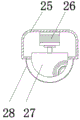
the monitoring assembly comprises a second shell, a second stepping motor is fixedly connected to the upper end of the inside of the second shell, a camera is fixedly connected to the output end of the second stepping motor, and a transparent protective cover is fixedly connected to the lower end of the second shell.
As a further description of the above technical solution:
the lithium battery is fixedly connected to one side of the bottom end of the supporting tube, and the expansion interface panel is fixedly connected to the other side of the bottom end of the supporting tube.
As a further description of the above technical solution:
the upper end of the expansion interface panel is fixedly connected with a control panel, and one side of the bottom end of the outer side of the supporting tube is in threaded connection with a cover plate.
The utility model discloses following beneficial effect has:
the intelligent security monitor is characterized in that a solar cell panel can charge a lithium battery, a first stepping motor can drive a turntable to rotate so as to drive the solar cell panel to rotate, the solar cell panel can face the direction of sun irradiation, the rotation range of the first stepping motor is in the range of 0-360 degrees, cameras in a monitoring component can perform functions of face recognition, night vision, dynamic tracking and the like, the cameras can rotate under the drive of a second stepping motor, the rotation range of the second stepping motor is in the range of 270 degrees in left-right deviation, the monitoring ranges of the two cameras can overlap to a certain extent, the existence of monitoring blind areas is reduced, a cover plate is opened, the servo motor can be controlled through a control panel, so that the output end of the servo motor drives a threaded rod to rotate under the deceleration of a speed reducer, thereby drive the connecting block downstream, and then drive the control subassembly downstream on the bracing piece, can make things convenient for the staff to clean transparent protection guard shield, the expansion interface panel is convenient to be upgraded and is reformed transform and maintain the control subassembly.
Drawings
Fig. 1 is a front view of the present invention;
FIG. 2 is a schematic view of the internal structure of the support tube of the present invention;
fig. 3 is a schematic structural diagram of the monitoring assembly of the present invention.
Illustration of the drawings:
1. supporting a tube; 2. a chute; 3. a cover plate; 4. a fixing plate; 5. a concrete block; 6. a support surface; 7. fixing the bolt; 8. a connecting rod; 9. a solar panel; 10. a support frame; 11. a turntable; 12. a first housing; 13. a support bar; 14. a monitoring component; 15. a threaded rod; 16. connecting blocks; 17. a first stepper motor; 18. a first gasket; 19. a servo motor; 20. a lithium battery; 21. an expansion interface panel; 22. a control panel; 23. a second gasket; 24. a speed reducer; 25. a second housing; 26. a second stepping motor; 27. a camera; 28. a transparent protective cover.
Detailed Description
The technical solutions in the embodiments of the present invention will be described clearly and completely with reference to the accompanying drawings in the embodiments of the present invention, and it is obvious that the described embodiments are only some embodiments of the present invention, not all embodiments. Based on the embodiments in the present invention, all other embodiments obtained by a person skilled in the art without creative work belong to the protection scope of the present invention.
In the description of the present invention, it should be noted that the terms "center", "upper", "lower", "left", "right", "vertical", "horizontal", "inner", "outer", and the like indicate orientations or positional relationships based on the orientations or positional relationships shown in the drawings, and are only for convenience of description and simplification of description, but do not indicate or imply that the device or element referred to must have a specific orientation, be constructed and operated in a specific orientation, and thus, should not be construed as limiting the present invention; the terms "first," "second," and "third" are used for descriptive purposes only and are not to be construed as indicating or implying relative importance, and furthermore, unless otherwise explicitly stated or limited, the terms "mounted," "connected," and "connected" are to be construed broadly and may be, for example, fixedly connected, detachably connected, or integrally connected; can be mechanically or electrically connected; they may be connected directly or indirectly through intervening media, or they may be interconnected between two elements. The specific meaning of the above terms in the present invention can be understood in specific cases to those skilled in the art.
Referring to fig. 1-3, the present invention provides an embodiment: an intelligent security monitor comprises a supporting surface 6, a concrete block 5 is embedded in the supporting surface 6, a fixing plate 4 is arranged at the upper end of the concrete block 5, a plurality of fixing bolts 7 are arranged between the fixing plate 4 and the concrete block 5, a supporting tube 1 is vertically and fixedly connected to the upper end of the fixing plate 4, a first shell 12 is highly connected to the upper end of the supporting tube 1, a first sealing gasket 18 and a second sealing gasket 23 are fixedly connected to the position, close to the bottom end, in the supporting tube 1, a servo motor 19 is fixedly connected to the upper end of the second sealing gasket 23, a speed reducer 24 is fixedly connected to the lower end of the first sealing gasket 18, the output end of the servo motor 19 is fixedly connected to the input end of the speed reducer 24, a threaded rod 15 is fixedly connected to the output end of the speed reducer 24 through the first sealing gasket 18, the upper end of the threaded rod 15 is, spout 2 has all been seted up to the both sides of stay tube 1, the equal fixedly connected with bracing piece 13 in both ends of connecting block 16, and the one end of a plurality of bracing pieces 13 passes respectively and corresponds spout 2.
A first stepping motor 17 is fixedly connected inside the first shell 12, and the output end of the first stepping motor 17 penetrates through the upper end of the first shell 12 and is fixedly connected with a rotary disc 11; the upper end of the turntable 11 is fixedly connected with a support frame 10, the upper end of the support frame 10 is provided with a solar cell panel 9, the arranged solar cell panel 9 can charge a lithium battery 20, and the first stepping motor 17 can drive the turntable 11 to rotate so as to drive the solar cell panel 9 to rotate, so that the solar cell panel can face the sun irradiation direction; one ends of the support rods 13 are fixedly connected with the connecting rods 8, and the lower ends of the connecting rods 8 are fixedly connected with the monitoring assemblies 14; the monitoring assembly 14 comprises a second shell 25, a second stepping motor 26 is fixedly connected to the upper end inside the second shell 25, a camera 27 is fixedly connected to the output end of the second stepping motor 26, and a transparent protective cover 28 is fixedly connected to the lower end of the second shell 25; one side of the bottom end in the support pipe 1 is fixedly connected with a lithium battery 20, the other side of the bottom end in the support pipe 1 is fixedly connected with an expansion interface panel 21, the camera 27 can be driven by a second stepping motor 26 to rotate, and the rotation range of the second stepping motor 26 is within the range of 270 degrees in a left-right offset manner, so that the monitoring ranges of the two cameras 27 can be overlapped to some extent, and the existence of monitoring blind areas is reduced; the upper end of the expansion interface panel 21 is fixedly connected with a control panel 22, and one side of the outer bottom end of the support tube 1 is in threaded connection with a cover plate 3.
The working principle is as follows: the concrete block 5 is embedded in the supporting surface 6, the mounting plate is fixed with the concrete block 5 through the fixing bolt 7, the device can be fixed, the arranged solar cell panel 9 can charge the lithium battery 20, the first stepping motor 17 can drive the turntable 11 to rotate so as to drive the solar cell panel 9 to rotate, the solar cell panel can face the direction of solar irradiation, the rotating range of the first stepping motor 17 is in the range of 0-360 degrees, the camera 27 in the monitoring assembly can perform the functions of face recognition, night vision, dynamic tracking and the like, the camera 27 can rotate under the driving of the second stepping motor 26, the rotating range of the second stepping motor 26 is shifted in the range of 270 degrees from left to right, the monitoring ranges of the two cameras 27 can have certain coincidence, and the existence of monitoring blind areas is reduced, open apron 3, can control servo motor 19 through control panel for servo motor 19's output drives threaded rod 15 and rotates under reduction gear 24's speed reduction, thereby drives connecting block 16 downstream, and then drives the control subassembly downstream on the bracing piece 13, can make things convenient for the staff to clean transparent protection guard shield, and expansion interface panel 21 conveniently upgrades transformation and maintenance to the control subassembly.
Finally, it should be noted that: although the present invention has been described in detail with reference to the foregoing embodiments, it will be apparent to those skilled in the art that modifications and variations can be made in the embodiments or in part of the technical features of the embodiments without departing from the spirit and the scope of the invention.
Claims (7)
1. The utility model provides an intelligence security protection watch-dog, includes holding surface (6), its characterized in that: the concrete block (5) is inlaid in the supporting surface (6), the fixing plate (4) is arranged at the upper end of the concrete block (5), a plurality of fixing bolts (7) are arranged between the fixing plate (4) and the concrete block (5), the supporting tube (1) is vertically and fixedly connected with the upper end of the fixing plate (4), the first shell (12) is highly connected with the upper end of the supporting tube (1), the position, close to the bottom end, of the inside of the supporting tube (1) is fixedly connected with a first sealing gasket (18) and a second sealing gasket (23), the upper end of the second sealing gasket (23) is fixedly connected with a servo motor (19), the speed reducer (24) is fixedly connected with the lower end of the first sealing gasket (18), the output end of the servo motor (19) is fixedly connected with the input end of the speed reducer (24), and the output end of the speed reducer (24) penetrates through the first sealing gasket (18) and a, the upper end of threaded rod (15) with the inside upper end of stay tube (1) is rotated and is connected, threaded connection has connecting block (16) on threaded rod (15), spout (2) have all been seted up to the both sides of stay tube (1), the equal fixedly connected with bracing piece (13) in both ends of connecting block (16), it is a plurality of the one end of bracing piece (13) is passed respectively and is corresponded spout (2).
2. The intelligent security monitor of claim 1, wherein: the inside fixedly connected with first step motor (17) of first casing (12), the upper end fixedly connected with carousel (11) of first casing (12) is run through to the output of first step motor (17).
3. The monitor of claim 2, wherein: the upper end fixedly connected with support frame (10) of carousel (11), the upper end of support frame (10) is provided with solar cell panel (9).
4. The intelligent security monitor of claim 1, wherein: a plurality of the equal fixedly connected with connecting rod (8) of one end of bracing piece (13), a plurality of the equal fixedly connected with of lower extreme of connecting rod (8) is kept watch on subassembly (14).
5. The intelligent security monitor of claim 4, wherein: the monitoring assembly (14) comprises a second shell (25), a second stepping motor (26) is fixedly connected to the upper end of the interior of the second shell (25), a camera (27) is fixedly connected to the output end of the second stepping motor (26), and a transparent protective cover (28) is fixedly connected to the lower end of the second shell (25).
6. The intelligent security monitor of claim 1, wherein: the lithium battery (20) is fixedly connected to one side of the bottom end of the supporting pipe (1), and the expansion interface panel (21) is fixedly connected to the other side of the bottom end of the supporting pipe (1).
7. The intelligent security monitor of claim 6, wherein: the upper end of the expansion interface panel (21) is fixedly connected with a control panel (22), and one side of the bottom end of the outer side of the supporting tube (1) is in threaded connection with a cover plate (3).
Priority Applications (1)
| Application Number | Priority Date | Filing Date | Title |
|---|---|---|---|
| CN202021680351.9U CN212986535U (en) | 2020-08-13 | 2020-08-13 | Wisdom security protection watch-dog |
Applications Claiming Priority (1)
| Application Number | Priority Date | Filing Date | Title |
|---|---|---|---|
| CN202021680351.9U CN212986535U (en) | 2020-08-13 | 2020-08-13 | Wisdom security protection watch-dog |
Publications (1)
| Publication Number | Publication Date |
|---|---|
| CN212986535U true CN212986535U (en) | 2021-04-16 |
Family
ID=75432830
Family Applications (1)
| Application Number | Title | Priority Date | Filing Date |
|---|---|---|---|
| CN202021680351.9U Active CN212986535U (en) | 2020-08-13 | 2020-08-13 | Wisdom security protection watch-dog |
Country Status (1)
| Country | Link |
|---|---|
| CN (1) | CN212986535U (en) |
Cited By (1)
| Publication number | Priority date | Publication date | Assignee | Title |
|---|---|---|---|---|
| CN113766126A (en) * | 2021-09-02 | 2021-12-07 | 安徽淮邦网络工程有限公司 | Intelligent security alarm system |
-
2020
- 2020-08-13 CN CN202021680351.9U patent/CN212986535U/en active Active
Cited By (1)
| Publication number | Priority date | Publication date | Assignee | Title |
|---|---|---|---|---|
| CN113766126A (en) * | 2021-09-02 | 2021-12-07 | 安徽淮邦网络工程有限公司 | Intelligent security alarm system |
Similar Documents
| Publication | Publication Date | Title |
|---|---|---|
| CN209762618U (en) | Camera for security protection monitored control system convenient to installation | |
| CN212986535U (en) | Wisdom security protection watch-dog | |
| CN211209812U (en) | Security protection supervisory equipment for building site | |
| CN210609405U (en) | Security monitoring device | |
| CN209201229U (en) | A kind of panoramic video security monitoring device | |
| CN212486604U (en) | Intelligent security monitoring device | |
| CN220910957U (en) | Protection device for security monitoring engineering | |
| CN219577160U (en) | Wisdom security protection's monitoring device | |
| CN113339648A (en) | Road electromechanical intelligent monitoring equipment and working method thereof | |
| CN206693746U (en) | Novel building engineering supervisory systems | |
| CN218301471U (en) | Public area security protection supervisory equipment | |
| CN216565417U (en) | Security protection supervisory equipment that radiating effect is good | |
| CN216252958U (en) | Intelligent camera device is used in security protection control | |
| CN219473130U (en) | Building epidemic prevention security protection supervisory equipment | |
| CN214222465U (en) | Adjustable security monitoring device | |
| CN213547674U (en) | Thing networking collection analysis supervisory equipment convenient to fixed mounting | |
| CN218845528U (en) | Intelligent security monitoring equipment | |
| CN211289305U (en) | Mounting bracket convenient to security protection supervisory equipment installation is dismantled | |
| CN212727215U (en) | Video monitoring security equipment | |
| CN213938108U (en) | Security protection supervisory equipment of broadcasting system | |
| CN216344900U (en) | Cable trench environment monitoring equipment | |
| CN213777080U (en) | But angle regulation's security protection monitoring device | |
| CN218565050U (en) | Entrance guard with monitoring function | |
| CN209991133U (en) | All-round security protection surveillance camera machine | |
| CN213028337U (en) | Intelligent security protection monitoring device of building |
Legal Events
| Date | Code | Title | Description |
|---|---|---|---|
| GR01 | Patent grant | ||
| GR01 | Patent grant |