CN212977614U - Non-standard gear manufacturing machine - Google Patents
Non-standard gear manufacturing machine Download PDFInfo
- Publication number
- CN212977614U CN212977614U CN202021419811.2U CN202021419811U CN212977614U CN 212977614 U CN212977614 U CN 212977614U CN 202021419811 U CN202021419811 U CN 202021419811U CN 212977614 U CN212977614 U CN 212977614U
- Authority
- CN
- China
- Prior art keywords
- dust collection
- base
- manufacturing machine
- dust
- gear manufacturing
- Prior art date
- Legal status (The legal status is an assumption and is not a legal conclusion. Google has not performed a legal analysis and makes no representation as to the accuracy of the status listed.)
- Active
Links
Images


Abstract
The utility model discloses a non-standard gear manufacturing machine, including the base of gear manufacturing machine, gear manufacturing machine's cutting mechanism, be used for placing the work piece the workstation, be used for carrying out the shock attenuation bearing structure that shock attenuation support was handled, be used for carrying out the first dust collection structure that the collection dirt was handled and be used for carrying out the second dust collection structure that the collection dirt was handled to the sweeps to the base, the bottom of base is being close to all being provided with the supporting leg in its four internal angle departments, cutting mechanism installs in the upper end surface of base, workstation fixed mounting is in the upper end surface of base, just the position of workstation and cutting mechanism's position phase-match. The utility model discloses it is better to the holistic shock attenuation buffering effect of machinery to effectual the risk that spare part damaged in the reduction mechanical equipment, and be convenient for carry out centralized processing to some sweeps and dust thing, avoid then that the staff is follow-up to making the machine and carry out cleaning work, and reduced the pollution to near environment, the practicality is higher.
Description
Technical Field
The utility model relates to a gear production facility field specifically is a non-standard gear manufacturing machine.
Background
The gear is a mechanical element with a rim on which the gear is continuously meshed to transmit motion and power, the gear is applied in transmission very early, at the end of 19 th century, the principle of generating a gear cutting method and the successive occurrence of a special machine tool and a cutter for cutting the gear by using the principle are realized, along with the development of production, the running stability of the gear is emphasized, and a manufacturing machine is required in the production process of the gear.
However, the conventional gear manufacturing machine has the following disadvantages:
1. in the process of gear cutting, large vibration can be generated, parts on a machine can be loosened and fall off after a long time, and even the parts on the machine can be damaged, so that the normal work of the parts is influenced, and unnecessary loss is caused.
2. The processing of concentrating is carried out to sweeps and dust thing that produce in the cutting process not convenient for can pollute near operational environment, and the follow-up staff of not being convenient for carries out cleaning to the machine, and the practicality is lower.
SUMMERY OF THE UTILITY MODEL
An object of the utility model is to provide a non-standard gear manufacturing machine to solve traditional gear manufacturing machine and at the in-process that carries out gear cutting processing, can produce great vibrations, it comes up to the end, can lead to spare part not hard up on the machine to drop, can damage the spare part on the machine even, influence its normal work, cause unnecessary loss, and simultaneously, be not convenient for carry out concentrated processing to sweeps and dust thing that produce in the cutting process, make can pollute the operational environment in near place, and be not convenient for follow-up staff to carry out cleaning to the machine, the lower problem of practicality.
In order to achieve the above object, the utility model provides a following technical scheme: a non-standard gear manufacturing machine comprises a base of the gear manufacturing machine, a cutting mechanism of the gear manufacturing machine, a workbench for placing a workpiece, a shock absorption supporting structure for shock absorption supporting treatment of the base, a first dust collection structure for dust collection treatment of scraps and a second dust collection structure for dust collection treatment of dust objects, wherein supporting legs are arranged at the positions close to four inner corners of the bottom of the base, the cutting mechanism is arranged on the upper end surface of the base, the workbench is fixedly arranged on the upper end surface of the base, the position of the workbench is matched with the position of the cutting mechanism, the shock absorption supporting structure is arranged at the bottoms of four supporting legs, mounting grooves which are penetrated through are arranged on the two sides of the upper end surface of the base on the two sides of the workbench, and the first dust collection structure is arranged on the two mounting grooves of the upper surface of the base, the second dust collecting structure is mounted to the bottom of the base.
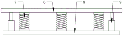
Preferably, shock attenuation bearing structure includes connecting plate, spring and backing plate, connecting plate and backing plate all are provided with two, two the top of connecting plate respectively with two supporting leg fixed connection with one side, the spring is provided with a plurality ofly, and is a plurality of spring equally divide into two sets ofly, and is two sets of the spring is fixed mounting respectively in the bottom of two connecting plates, two the top of backing plate respectively with the bottom fixed connection of two sets of springs.
Preferably, a plurality of telescopic supporting rods are installed at the tops of the two base plates, and the tops of the telescopic supporting rods are fixedly connected with the bottoms of the connecting plates.
Preferably, the first dust collecting structure comprises two dust collecting boxes, one side, away from each other, of each dust collecting box is provided with an extension plate, the top of each extension plate is provided with a handle, the two dust collecting boxes are movably clamped in the two mounting grooves respectively, and the bottom ends of the inner parts of the two dust collecting boxes are designed in a net leakage mode.
Preferably, the upper end surface of base all laminates in the both sides of workstation and is provided with the guide block that is the design of inclined plane type, just the bottom of guide block inclines towards in the mounting groove.
Preferably, the second dust collecting structure comprises a dust collecting box and a dust collecting cover, the dust collecting box is fixedly mounted at the bottom of the base through a mounting frame, a water inlet and a water outlet are formed in one side of the front face of the dust collecting box, a ventilation opening is formed in the top of the dust collecting box, a dust screen cover is arranged at the ventilation opening, the two groups of dust collecting covers are fixedly mounted at the top of the dust collecting box, the bottom of each dust collecting cover is communicated with the inside of the dust collecting box, the positions of the two groups of dust collecting covers are respectively matched with the positions of the bottoms of the two dust collecting boxes, and dust collecting fans are mounted in the two groups of dust collecting covers.
The utility model provides a nonstandard gear manufacturing machine possesses following beneficial effect:
(1) the utility model discloses a be provided with shock attenuation bearing structure for when carrying out the production and processing work of gear, can carry out effectual shock attenuation buffering to the base through shock attenuation bearing structure, thereby effectual reduced on the machine part appear become flexible come off or even the risk of damage, then effectual avoided influencing mechanical normal work, also effectually avoided causing the unnecessary loss.
(2) The utility model discloses a be provided with first dust collecting structure and second dust collecting structure for when carrying out the processing work of gear, can concentrate to some great sweeps through first dust collecting structure and collect the processing, and can carry out further centralized processing to the dust thing through second dust collecting structure, effectually avoided polluting near operational environment, and the staff of being convenient for is follow-up to carry out cleaning process work to machinery, and the practicality is higher.
Drawings
Fig. 1 is a schematic view of the overall structure of the present invention;
FIG. 2 is a top view of the workbench according to the present invention;
FIG. 3 is a top view of the dust cage of the present invention;
fig. 4 is a side view of the installation of the cushion plate of the present invention.
In the figure: 1. a base; 2. a cutting mechanism; 3. a work table; 4. supporting legs; 5. mounting grooves; 6. a connecting plate; 7. a spring; 8. a base plate; 9. a telescopic support rod; 10. a dust collecting box; 11. an extension plate; 12. a guide block; 13. a dust collection box; 14. a dust collection cover; 15. a mounting frame; 16. a vent; 17. a dust collection fan.
Detailed Description
The technical solution in the embodiments of the present invention will be clearly and completely described below with reference to the accompanying drawings in the embodiments of the present invention.
As shown in fig. 1-4, the utility model provides a technical solution: a non-standard gear manufacturing machine comprises a base 1 of the gear manufacturing machine, a cutting mechanism 2 of the gear manufacturing machine, a workbench 3 for placing a workpiece, a shock absorption supporting structure for shock absorption supporting treatment of the base 1, a first dust collection structure for dust collection treatment of scraps and a second dust collection structure for dust collection treatment of dust, wherein the bottom of the base 1 is provided with supporting legs 4 close to four inner corners of the base, the cutting mechanism 2 is installed on the upper end surface of the base 1, the workbench 3 is fixedly installed on the upper end surface of the base 1, the position of the workbench 3 is matched with the position of the cutting mechanism 2, the shock absorption supporting structure is installed at the bottoms of the four supporting legs 4, the upper end surface of the base 1 is provided with mounting grooves 5 penetrating through two sides of the workbench 3, the first dust collection structure is installed on two mounting grooves 5 of the upper surface of the base 1, the second dust collecting structure is installed to the bottom of the base 1.
The damping support structure comprises two connecting plates 6, two springs 7 and two backing plates 8, the tops of the two connecting plates 6 are fixedly connected with the two supporting legs 4 on the same side respectively, the springs 7 are provided with a plurality of springs 7, the springs 7 are divided into two groups at equal intervals, the two groups of springs 7 are fixedly installed at the bottoms of the two connecting plates 6 respectively, and the tops of the two backing plates 8 are fixedly connected with the bottoms of the two groups of springs 7 respectively, so that when the gear is machined, vibration generated when the base 1 is machined can be effectively buffered and damped by matching the two groups of springs 7 and the two connecting plates 6 through the two backing plates 8, and the risk that parts are loosened and fall off or even damaged in machinery is effectively reduced;
the top parts of the two backing plates 8 are respectively provided with a plurality of telescopic supporting rods 9, and the top parts of the telescopic supporting rods 9 are fixedly connected with the bottom part of the connecting plate 6, so that the stability of the base 1 during shock absorption can be improved through the telescopic supporting rods 9;
the first dust collection structure comprises two dust collection boxes 10, wherein extension plates 11 are arranged on the sides, far away from each other, of the two dust collection boxes 10, handles are arranged at the tops of the extension plates 11, the two dust collection boxes 10 are movably clamped in the two mounting grooves 5 respectively, and the bottom ends of the inner parts of the two dust collection boxes 10 are both in a net leakage type design, so that when the gear is machined, scraps produced by machining can slide to the mounting grooves 5 through the guide blocks 12 and then fall into the dust collection boxes 10, and therefore certain large scraps are intensively treated;
the upper end surface of the base 1 is provided with guide blocks 12 in an inclined plane type design in a manner of being attached to two sides of the workbench 3, and the bottoms of the guide blocks 12 incline towards the mounting groove 5, so that when the gear is machined, the waste scraps can be guided by the guide blocks 12, and most of the waste scraps can slide into the dust collection box 10 in the mounting groove 5;
the second dust collecting structure comprises a dust collecting box 13 and dust collecting covers 14, the dust collecting box 13 is fixedly arranged at the bottom of the base 1 through a mounting frame 15, a water inlet and a water outlet are formed in one side of the front surface of the dust collecting box 13, a vent 16 is formed in the top of the dust collecting box 13, a dust screen cover is arranged at the vent 16, the dust collecting covers 14 are provided with two groups, the two groups of dust collecting covers 14 are fixedly arranged at the top of the dust collecting box 13, the bottom of the dust collecting cover 14 is communicated and connected with the inside of the dust collecting box 13, the positions of the two groups of dust collecting covers 14 are respectively matched with the positions of the bottoms of the two dust collecting boxes 10, and dust collecting fans 17 are arranged in the two groups of dust collecting covers 14, so that clean water can be injected into the dust collecting box 13 in advance when the gear machining work is carried out, and then, thus, the dust collecting box 10 with the bottom in a leakage net type design is matched to absorb some smaller dust objects and convey the smaller dust objects into the dust collecting box 13, so that the drifting of the dust objects is effectively reduced, the pollution to the nearby environment is reduced, and the practicability is higher;
it is understood that the dust collection fan 17 is externally connected with a control switch and a driving source.
The working principle is as follows: when the gear is machined, the vibration generated during machining of the base 1 can be effectively buffered and damped by matching the two base plates 8 with the two sets of springs 7 and the two connecting plates 6, so that the risk that parts are loosened and fall off or even damaged in the machine is effectively reduced, and when the gear is machined, scraps generated during machining can slide to the mounting groove 5 through the guide block 12 and then fall into the dust collection box 10, so that the large scraps are intensively treated, meanwhile, clear water can be injected into the dust collection box 13 in advance, and then the dust collection fans 17 in the two sets of dust collection covers 14 are started, so that the dust collection box 10 with the bottom in a leakage net type design is matched, small dust objects are absorbed and conveyed into the dust collection box 13, the scattering of the dust objects is effectively reduced, and the pollution to the nearby environment is reduced, the practicability is higher.
Although embodiments of the present invention have been shown and described, it will be appreciated by those skilled in the art that changes, modifications, substitutions and alterations can be made in these embodiments without departing from the principles and spirit of the invention, the scope of which is defined in the appended claims and their equivalents.
Claims (6)
1. A nonstandard gear manufacturing machine comprises a base (1) of the gear manufacturing machine, a cutting mechanism (2) of the gear manufacturing machine, a workbench (3) for placing a workpiece, a damping support structure for damping support treatment of the base (1), a first dust collection structure for collecting dust of scraps and a second dust collection structure for collecting dust of dust, and is characterized in that: the bottom of base (1) is being close to and all is being provided with supporting leg (4) in its four internal angle departments, cutting mechanism (2) are installed in the upper end surface of base (1), workstation (3) fixed mounting is in the upper end surface of base (1), just the position of workstation (3) and the position phase-match of cutting mechanism (2), shock attenuation bearing structure installs in the bottom of four supporting legs (4), mounting groove (5) that run through are all seted up in the both sides of workstation (3) to the upper end surface of base (1), first collection dirt structural mounting is in two mounting groove (5) departments of the upper surface of base (1), the bottom of second collection dirt structural mounting and base (1).
2. A non-standard gear manufacturing machine according to claim 1, wherein: shock attenuation bearing structure includes connecting plate (6), spring (7) and backing plate (8), connecting plate (6) and backing plate (8) all are provided with two, two the top of connecting plate (6) respectively with two supporting legs (4) fixed connection with one side, spring (7) are provided with a plurality ofly, and are a plurality of spring (7) etc. divide into two sets ofly, two sets of spring (7) fixed mounting is respectively in the bottom of two connecting plates (6), two the top of backing plate (8) respectively with the bottom fixed connection of two sets of springs (7).
3. A non-standard gear manufacturing machine according to claim 2, wherein: two a plurality of flexible bracing pieces (9) are all installed at the top of backing plate (8), just the top of flexible bracing piece (9) and the bottom fixed connection of connecting plate (6).
4. A non-standard gear manufacturing machine according to claim 1, wherein: the first dust collection structure comprises two dust collection boxes (10), wherein one side, far away from each other, of each dust collection box (10) is provided with an extension plate (11), the top of each extension plate (11) is provided with a handle, the two dust collection boxes (10) are movably clamped in two mounting grooves (5) respectively, and the bottom ends of the insides of the two dust collection boxes (10) are designed in a net leakage mode.
5. A non-standard gear manufacturing machine according to claim 1, wherein: the upper end surface of base (1) all laminates in the both sides of workstation (3) and is provided with guide block (12) that are the design of inclined plane type, just the bottom of guide block (12) is towards the slope in mounting groove (5).
6. A non-standard gear manufacturing machine according to claim 1, wherein: the second dust collection structure comprises a dust collection box (13) and a dust collection cover (14), the dust collection box (13) is fixedly mounted at the bottom of the base (1) through a mounting frame (15), a water inlet and a water outlet are formed in one side of the front face of the dust collection box (13), a ventilation opening (16) is formed in the top of the dust collection box (13), a dust screen cover is arranged at the ventilation opening (16), the dust collection cover (14) is provided with two groups, the two groups of dust collection covers (14) are fixedly mounted at the top of the dust collection box (13), the bottom of the dust collection cover (14) is communicated and connected with the inside of the dust collection box (13), the positions of the two groups of dust collection covers (14) are respectively matched with the positions of the bottoms of the two dust collection boxes (10), and a dust collection fan (17) is mounted inside the two groups of dust collection.
Priority Applications (1)
| Application Number | Priority Date | Filing Date | Title |
|---|---|---|---|
| CN202021419811.2U CN212977614U (en) | 2020-07-19 | 2020-07-19 | Non-standard gear manufacturing machine |
Applications Claiming Priority (1)
| Application Number | Priority Date | Filing Date | Title |
|---|---|---|---|
| CN202021419811.2U CN212977614U (en) | 2020-07-19 | 2020-07-19 | Non-standard gear manufacturing machine |
Publications (1)
| Publication Number | Publication Date |
|---|---|
| CN212977614U true CN212977614U (en) | 2021-04-16 |
Family
ID=75428046
Family Applications (1)
| Application Number | Title | Priority Date | Filing Date |
|---|---|---|---|
| CN202021419811.2U Active CN212977614U (en) | 2020-07-19 | 2020-07-19 | Non-standard gear manufacturing machine |
Country Status (1)
| Country | Link |
|---|---|
| CN (1) | CN212977614U (en) |
-
2020
- 2020-07-19 CN CN202021419811.2U patent/CN212977614U/en active Active
Similar Documents
| Publication | Publication Date | Title |
|---|---|---|
| CN210588614U (en) | Polishing device for machining | |
| CN216461983U (en) | Precise numerical control planer type milling machine capable of cutting at high speed | |
| CN212977614U (en) | Non-standard gear manufacturing machine | |
| CN219684267U (en) | Dust removing structure of three-dimensional five-axis laser cutting machine | |
| CN211218812U (en) | Shell drilling equipment for motor machining | |
| CN218397188U (en) | Mechanical sealing part machining milling machine capable of performing centralized processing on chippings | |
| CN217668194U (en) | Horizontal deep hole drilling and boring machine for processing porous workpiece | |
| CN216268410U (en) | Novel high-efficient stable cnc engraving and milling machine | |
| CN213702681U (en) | Dust collector during engraver operation | |
| CN214868940U (en) | Hydraulic clamp for flywheel housing machining | |
| CN114952554A (en) | Automatic grinding device | |
| CN214053827U (en) | Planer with dust removal function | |
| CN209850463U (en) | Dust removal equipment for hardware machining | |
| CN213320627U (en) | Multifunctional cutting machine for processing plate-type furniture | |
| CN206811602U (en) | A kind of novel numerical control lathe for machining | |
| CN217859899U (en) | Large-scale high-speed drilling and milling machine special for hydraulic module frame | |
| CN220862876U (en) | Protective device for machining | |
| CN213317954U (en) | Milling machine that possesses garbage collection function | |
| CN216372471U (en) | Intelligent numerical control cutting machine | |
| CN214922630U (en) | Machine tool with noise reduction structure | |
| CN211493477U (en) | Dust suction device of wood carving machine | |
| CN220717870U (en) | Crown block type gantry engraving and milling machine | |
| CN219768442U (en) | Cutting device for model design | |
| CN218503386U (en) | Automobile parts's drilling structure | |
| CN215616803U (en) | Environment-friendly dust removal device for milling machine |
Legal Events
| Date | Code | Title | Description |
|---|---|---|---|
| GR01 | Patent grant | ||
| GR01 | Patent grant |