CN212954574U - Oil-water separator - Google Patents
Oil-water separator Download PDFInfo
- Publication number
- CN212954574U CN212954574U CN202021663012.XU CN202021663012U CN212954574U CN 212954574 U CN212954574 U CN 212954574U CN 202021663012 U CN202021663012 U CN 202021663012U CN 212954574 U CN212954574 U CN 212954574U
- Authority
- CN
- China
- Prior art keywords
- oil
- fixedly connected
- tank
- pipe
- water separator
- Prior art date
- Legal status (The legal status is an assumption and is not a legal conclusion. Google has not performed a legal analysis and makes no representation as to the accuracy of the status listed.)
- Expired - Fee Related
Links
Images

Landscapes
- Removal Of Floating Material (AREA)
Abstract
The utility model discloses an oil-water separator, including the setting tank, the right-hand member fixed mounting at setting tank top has first pump machine, defeated oil pipe of output fixedly connected with of first pump machine, the input fixedly connected with of first pump machine inhales oil pipe, the top left side fixedly connected with agitator tank of setting tank, the top fixed mounting of agitator tank has the motor. The utility model discloses people arrange the inside of oil water to the agitator tank through the oral siphon, through PLC controller starter motor work, through motor start puddler work, after evenly stirring oil water through the puddler, start second solenoid valve work through the PLC controller, oil water separation's effect has been reached, current oil water separator has been solved, at the during operation, do not wash the work efficiency that can reduce the separator to the separator for a long time, lead to the discharged water can carry a large amount of oil stains, thereby destroy ecological environment's problem.
Description
Technical Field
The utility model relates to an oil water separator technical field specifically is oil water separator.
Background
The oil-water separator is a device which is divided into a catering oil-water separator and an industrial oil-water separator, and the catering oil-water separator is used for treating sewage in the catering industry; because of the requirement of environmental protection, the produced sewage of boats and ships machine is arranged in rivers lake sea must be handled, needs to use industry oil water separator, and current oil water separator, at the during operation, does not wash the separator for a long time can reduce the work efficiency of separator, leads to the discharged water to carry a large amount of oil stains to destroy ecological environment, for this reason, we propose oil water separator.
SUMMERY OF THE UTILITY MODEL
An object of the utility model is to provide an oil water separator possesses high-efficient oil water separating's advantage, has solved current oil water separator, at the during operation, does not wash the work efficiency that can reduce the separator to the separator for a long time, leads to the discharged water can carry a large amount of oil stains to destroy ecological environment's problem.
In order to achieve the above object, the utility model provides a following technical scheme: oil water separator, including the setting tank, the right-hand member fixed mounting at setting tank top has first pump machine, defeated oil pipe of output fixedly connected with of first pump machine, the input fixedly connected with of first pump machine inhales oil pipe, the top left side fixedly connected with agitator tank of setting tank, the top fixed mounting of agitator tank has the motor, the output fixedly connected with puddler of motor, the bottom swing joint of puddler is in the top of setting tank, the middle-end fixed mounting on setting tank right side has the second pump machine, the input fixedly connected with conveyer pipe of second pump machine, the output fixedly connected with water pipe of second pump machine, the right-hand member fixedly connected with rose box of water pipe, movable mounting has the active carbon filter in the inner chamber of rose box.
Preferably, the top fixedly connected with oral siphon of agitator tank inner chamber, the top left side fixedly connected with drain pipe of setting tank inner chamber, the fixed surface of drain pipe is connected with the second solenoid valve, the bottom left end fixedly connected with drain pipe of rose box inner chamber, the fixed surface of drain pipe is connected with first solenoid valve.
Preferably, the right end of the stirring tank is fixedly connected with a fixed support, and the inner side of the fixed support is fixedly connected with an oil storage tank.
Preferably, the top of the inner cavity of the oil storage tank is fixedly connected with a discharge pipe, and the top of the discharge pipe is fixedly connected with a connecting port.
Preferably, the bottom of the oil suction pipe is in threaded connection with a floating block, the front of the stirring box is fixedly provided with a PLC (programmable logic controller), and the front of the filtering box is movably connected with a movable door through a hinge.
Compared with the prior art, the beneficial effects of the utility model are as follows:
1. the utility model discloses people arrange the profit to the inside of agitator tank through the oral siphon, start motor work through the PLC controller, start the puddler work through the motor, after evenly stirring the profit through the puddler, start second solenoid valve work through the PLC controller, discharge the mixed profit into the inside of setting tank through the drain pipe, through the setting of kicking block, make the profit jack up the kicking block through buoyancy, drive the surface that the oil absorption pipe contacted the greasy dirt through the come-up of kicking block, start first pump machine work through the PLC controller, make the oil absorption pipe carry most oil stains to oil pipe through first pump machine, enter the oil storage tank through oil pipe transport, carry oil stains to the connector through the delivery pipe and collect the processing to the oil stains, at this moment, start second pump machine work through the PLC controller, carry water and remaining oil stains inlet tube through the delivery pipe, discharge through the water pipe and get into the rose box, filter the oil stain through the active carbon filter, start first solenoid valve through the PLC controller and discharge away clean water source, reached water oil separating's effect, solved current oil water separator, at the during operation, do not wash the work efficiency that can reduce the separator to the separator for a long time, lead to the discharged water can carry a large amount of oil stains to destroy ecological environment's problem.
2. The utility model discloses a setting of kicking block for inhale oil pipe can with the surface contact of oil stain, avoid inhaling the unable extraction oil stain of oil pipe, through the setting of dodge gate, can regularly dismantle and clear up the active carbon filter, through the setting of puddler, can fully homogenize oil and water, when the bottom of setting tank deposits, can accelerate the speed of oil stain come-up.
Drawings
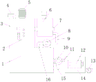
FIG. 1 is a front view of the structure of the present invention;
FIG. 2 is a sectional view of the structure of the present invention;
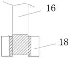
fig. 3 is a sectional view of the floating block of the present invention.
In the figure: 1. a settling tank; 2. a PLC controller; 3. a stirring box; 4. a water inlet pipe; 5. a motor; 6. an oil storage tank; 7. fixing a bracket; 8. a first pump; 9. an oil delivery pipe; 10. a second pump; 11. a water pipe; 12. a movable door; 13. a first solenoid valve; 14. a filter box; 15. a delivery pipe; 16. an oil suction pipe; 17. an activated carbon filter plate; 18. floating blocks; 19. a discharge pipe; 20. a connecting port; 21. a stirring rod; 22. a second solenoid valve; 23. and a water discharge pipe.
Detailed Description
The technical solutions in the embodiments of the present invention will be described clearly and completely with reference to the accompanying drawings in the embodiments of the present invention, and it is obvious that the described embodiments are only some embodiments of the present invention, not all embodiments. Based on the embodiments in the present invention, all other embodiments obtained by a person skilled in the art without creative work belong to the protection scope of the present invention.
In the description of the present invention, it should be noted that the terms "upper", "lower", "inner", "outer", "front end", "rear end", "both ends", "one end", "the other end", and the like indicate orientations or positional relationships based on the orientations or positional relationships shown in the drawings, and are only for convenience of description and simplification of description, but do not indicate or imply that the device or element to be referred must have a specific orientation, be constructed in a specific orientation, and be operated, and thus, should not be construed as limiting the present invention. Furthermore, the terms "first" and "second" are used for descriptive purposes only and are not to be construed as indicating or implying relative importance.
In the description of the present invention, it is to be noted that, unless otherwise explicitly specified or limited, the terms "mounted", "provided", "connected", and the like are to be construed broadly, such as "connected", which may be fixedly connected, detachably connected, or integrally connected; can be mechanically or electrically connected; they may be connected directly or indirectly through intervening media, or they may be interconnected between two elements. The specific meaning of the above terms in the present invention can be understood in specific cases to those skilled in the art.
The utility model discloses a setting tank 1, PLC controller 2, agitator tank 3, oral siphon 4, motor 5, oil storage tank 6, fixed bolster 7, first pump machine 8, defeated oil pipe 9, second pump machine 10, water pipe 11, dodge gate 12, first solenoid valve 13, rose box 14, conveyer pipe 15, oil absorption pipe 16, active carbon filter 17, floating block 18, discharge pipe 19, connector 20, puddler 21, second solenoid valve 22 and drain pipe 23 part are the parts that general standard or technical personnel in the field know, its structure and principle all are that this technical personnel all can learn through the technical manual or learn through conventional experimental method.
Referring to fig. 1-3, the oil-water separator comprises a settling tank 1, a first pump 8 is fixedly installed at the right end of the top of the settling tank 1, an oil delivery pipe 9 is fixedly connected to the output end of the first pump 8, an oil suction pipe 16 is fixedly connected to the input end of the first pump 8, a stirring tank 3 is fixedly connected to the left side of the top of the settling tank 1, a motor 5 is fixedly installed at the top of the stirring tank 3, a stirring rod 21 is fixedly connected to the output end of the motor 5, the bottom of the stirring rod 21 is movably connected to the top of the settling tank 1, a second pump 10 is fixedly installed at the middle end of the right side of the settling tank 1, a delivery pipe 15 is fixedly connected to the input end of the second pump 10, a water pipe 11 is fixedly connected to the output end of the second pump 10, a filter tank 14 is fixedly connected to the right end of the water pipe 11, an activated carbon filter plate 17 is movably installed in, the left side of the top of the inner cavity of the settling tank 1 is fixedly connected with a drain pipe 23, the surface of the drain pipe 23 is fixedly connected with a second electromagnetic valve 22, the left side of the bottom of the inner cavity of the filter tank 14 is fixedly connected with a drain pipe, the surface of the drain pipe is fixedly connected with a first electromagnetic valve 13, the right end of the stirring tank 3 is fixedly connected with a fixed support 7, the inner side of the fixed support 7 is fixedly connected with an oil storage tank 6, the top of the inner cavity of the oil storage tank 6 is fixedly connected with a discharge pipe 19, the top of the discharge pipe 19 is fixedly connected with a connecting port 20, the bottom of the oil suction pipe 16 is in threaded connection with a floating block 18, the front of the stirring tank 3 is fixedly provided with a PLC (programmable logic controller) 2, the front of the filter tank 14 is movably connected with a movable door 12 through a hinge, through the arrangement of the floating block 18, the oil suction, through the setting of puddler 21, can fully homogenize oil and water, when the bottom of setting 1 of setting tank deposits, can accelerate the speed of oil stain come-up.
When the oil stain collecting device is used, people drain oil water into the stirring box 3 through the water inlet pipe 4, the PLC controller 2 starts the motor 5 to work, the motor 5 starts the stirring rod 21 to work, the PLC controller 2 starts the second electromagnetic valve 22 to work after the oil water is uniformly stirred through the stirring rod 21, the mixed oil water is discharged into the settling box 1 through the water discharge pipe 23, the floating block 18 is arranged to jack up the floating block 18 through buoyancy, the oil suction pipe 16 is driven to contact with the surface of oil stains through the floating block 18, the PLC controller 2 starts the first pump 8 to work, the oil suction pipe 16 conveys most of oil stains to the oil conveying pipe 9 through the first pump 8, the oil stains are conveyed into the oil storage box 6 through the oil conveying pipe 9 and conveyed to the connecting port 20 through the discharge pipe 19 to collect the oil stains, at the moment, the PLC controller 2 starts the second pump 10 to work, carry inlet tube 11 with water and remaining oil stain through conveyer pipe 15, it gets into rose box 14 to discharge through water pipe 11, filter the oil stain through active carbon filter 17, it discharges away clean water source to start first solenoid valve 13 through PLC controller 2, oil water separating's effect has been reached, current oil water separator has been solved, at the during operation, do not wash the work efficiency that can reduce the separator to the separator for a long time, lead to the discharged water can carry a large amount of oil stains, thereby destroy ecological environment's problem.
Although embodiments of the present invention have been shown and described, it will be appreciated by those skilled in the art that changes, modifications, substitutions and alterations can be made in these embodiments without departing from the principles and spirit of the invention, the scope of which is defined in the appended claims and their equivalents.
Claims (5)
1. Oil water separator, including setting tank (1), its characterized in that: the oil-water separator is characterized in that a first pump (8) is fixedly mounted at the right end of the top of the settling tank (1), an oil delivery pipe (9) is fixedly connected with the output end of the first pump (8), an oil suction pipe (16) is fixedly connected with the input end of the first pump (8), a stirring tank (3) is fixedly connected with the left side of the top of the settling tank (1), a motor (5) is fixedly mounted at the top of the stirring tank (3), a stirring rod (21) is fixedly connected with the output end of the motor (5), the bottom of the stirring rod (21) is movably connected with the top of the settling tank (1), a second pump (10) is fixedly mounted at the middle end of the right side of the settling tank (1), a conveying pipe (15) is fixedly connected with the input end of the second pump (10), a water pipe (11) is fixedly connected with the output end of the second pump (10), and a filter tank (14) is fixedly connected with, an active carbon filter plate (17) is movably arranged in the inner cavity of the filter box (14).
2. The oil-water separator of claim 1, wherein: the top fixedly connected with oral siphon (4) of agitator tank (3) inner chamber, the top left side fixedly connected with drain pipe (23) of setting tank (1) inner chamber, the fixed surface of drain pipe (23) is connected with second solenoid valve (22), the bottom left end fixedly connected with drain pipe of rose box (14) inner chamber, the fixed surface of drain pipe is connected with first solenoid valve (13).
3. The oil-water separator of claim 1, wherein: the right-hand member fixedly connected with fixed bolster (7) of agitator tank (3), the inboard fixedly connected with batch oil tank (6) of fixed bolster (7).
4. The oil-water separator according to claim 3, wherein: the top fixedly connected with delivery pipe (19) of oil storage tank (6) inner chamber, the top fixedly connected with connector (20) of delivery pipe (19).
5. The oil-water separator of claim 1, wherein: the bottom of the oil suction pipe (16) is in threaded connection with a floating block (18), the front of the stirring box (3) is fixedly provided with a PLC (programmable logic controller) controller (2), and the front of the filtering box (14) is movably connected with a movable door (12) through a hinge.
Priority Applications (1)
| Application Number | Priority Date | Filing Date | Title |
|---|---|---|---|
| CN202021663012.XU CN212954574U (en) | 2020-08-11 | 2020-08-11 | Oil-water separator |
Applications Claiming Priority (1)
| Application Number | Priority Date | Filing Date | Title |
|---|---|---|---|
| CN202021663012.XU CN212954574U (en) | 2020-08-11 | 2020-08-11 | Oil-water separator |
Publications (1)
| Publication Number | Publication Date |
|---|---|
| CN212954574U true CN212954574U (en) | 2021-04-13 |
Family
ID=75352944
Family Applications (1)
| Application Number | Title | Priority Date | Filing Date |
|---|---|---|---|
| CN202021663012.XU Expired - Fee Related CN212954574U (en) | 2020-08-11 | 2020-08-11 | Oil-water separator |
Country Status (1)
| Country | Link |
|---|---|
| CN (1) | CN212954574U (en) |
-
2020
- 2020-08-11 CN CN202021663012.XU patent/CN212954574U/en not_active Expired - Fee Related
Similar Documents
| Publication | Publication Date | Title |
|---|---|---|
| CN112340804A (en) | Vertical flow type air flotation machine for wastewater treatment | |
| CN109650586A (en) | A kind of oil water separator for kitchen waste water filtering | |
| CN212954574U (en) | Oil-water separator | |
| CN212532574U (en) | Oil-water separation micro-electrolysis device | |
| CN209338259U (en) | Engine of boat and ship washing tail gas water treatment system | |
| CN214880639U (en) | Multistage sewage treatment device | |
| CN215102227U (en) | Biological oxidation tank convenient for cleaning impurities | |
| CN215924579U (en) | Automatic oil-water separation device for fossil oil chemical industry | |
| CN214004293U (en) | Centrifugal separation device for sewage treatment | |
| CN213707799U (en) | Scum treatment device of air floatation machine | |
| CN210419306U (en) | High-efficient integration sewage treatment complete sets | |
| CN112875806A (en) | Modularized multifunctional solid-liquid separation system | |
| CN219929694U (en) | Miniature air supporting device of oily waste water treatment | |
| CN219507725U (en) | Multistage sewage filtering device | |
| CN217758658U (en) | Improved water environment treatment device | |
| CN214880741U (en) | Intelligent groundwater remediation treatment facility | |
| CN216106343U (en) | Oil-water separation device in kitchen waste wastewater treatment | |
| CN215799031U (en) | Sewage treatment recycles device | |
| CN215924494U (en) | Full-automatic air supporting machine of pharmaceutical factory | |
| CN220736362U (en) | Sludge cleaning device of sludge sedimentation tank | |
| CN213655260U (en) | Submersible high-lift flat-mouth monitorable hydraulic slurry pump | |
| CN217757055U (en) | Oil stain pretreatment equipment for efficient sewage draining outlet | |
| CN211283993U (en) | Bury formula sewage treatment device | |
| CN217264937U (en) | Automatic cleaning device for air floatation and air dissolution system | |
| CN216377765U (en) | Sewage precipitation filter equipment |
Legal Events
| Date | Code | Title | Description |
|---|---|---|---|
| GR01 | Patent grant | ||
| GR01 | Patent grant | ||
| CF01 | Termination of patent right due to non-payment of annual fee | ||
| CF01 | Termination of patent right due to non-payment of annual fee |
Granted publication date: 20210413 Termination date: 20210811 |