CN212946993U - Furniture trimming device - Google Patents
Furniture trimming device Download PDFInfo
- Publication number
- CN212946993U CN212946993U CN202021513284.1U CN202021513284U CN212946993U CN 212946993 U CN212946993 U CN 212946993U CN 202021513284 U CN202021513284 U CN 202021513284U CN 212946993 U CN212946993 U CN 212946993U
- Authority
- CN
- China
- Prior art keywords
- fixed mounting
- fixedly mounted
- plate
- furniture
- filter box
- Prior art date
- Legal status (The legal status is an assumption and is not a legal conclusion. Google has not performed a legal analysis and makes no representation as to the accuracy of the status listed.)
- Expired - Fee Related
Links
Images
Landscapes
- Filtering Of Dispersed Particles In Gases (AREA)
Abstract
The utility model belongs to furniture processing equipment field, especially, furniture deburring device is not convenient for restrain and collect the piece that produces polishing to current deburring equipment, influences operational environment's problem easily, presents following scheme, and it includes the bottom plate, the top fixed mounting of bottom plate has two supports, and the top fixed mounting of two supports has same roof, and the rotation hole has been seted up to the bottom of roof, rotates downthehole rotation and installs the dwang, one side fixed mounting of support has the connecting plate, and the top of connecting plate is rotated and is installed the edging roller, the bottom fixed mounting of dwang is at the top of edging roller, and the top fixed mounting of dwang has the eccentric wheel, and the spring groove has been seted up at the top of roof, and slidable mounting has the movable plate in the spring groove. The utility model discloses rational in infrastructure, convenient operation, this deburring equipment are convenient for restrain and collect the piece that grinds the production, can not influence operational environment.
Description
Technical Field
The utility model relates to a furniture processing equipment technical field especially relates to a furniture deburring device.
Background
The existing method for trimming the panel furniture is that after the edge of the panel is trimmed, the melted glue is directly coated on the edge of the panel, and finally, a banding area is fixed on the edge of the panel;
however, the existing trimming equipment is inconvenient to restrain and collect the scraps generated by grinding, and easily influences the working environment.
Disclosure of Invention
The utility model aims at solving the problem that the trimming equipment is not convenient for restraining and collecting the scraps generated by polishing in the prior art, and the shortcoming of the working environment is easily influenced, thereby providing a furniture trimming device.
In order to achieve the above purpose, the utility model adopts the following technical scheme:
a furniture trimming device comprises a bottom plate, wherein two supports are fixedly mounted at the top of the bottom plate, the top of the two supports is fixedly provided with a same top plate, the bottom of the top plate is provided with a rotating hole, a rotating rod is rotatably mounted in the rotating hole, one side of each support is fixedly provided with a connecting plate, the top of each connecting plate is rotatably provided with a trimming roller, the bottom of each rotating rod is fixedly mounted at the top of the trimming roller, the top of each rotating rod is fixedly provided with an eccentric wheel, the top of the top plate is provided with a spring groove, a moving plate is slidably mounted in the spring groove, one side of the moving plate is in contact with the eccentric wheel, one end of the spring, far away from the moving plate, is fixedly mounted on the inner wall of one side of the spring groove, the other side of, the bottom fixed mounting of filter cartridge has the dust absorption pipe, the apron is installed at the top of filter cartridge, and the dead lever is installed to the bottom of apron, and the bottom fixed mounting of dead lever has the filter screen, and the filter screen is installed in filter cartridge, installs two separation blades on the bottom inner wall of filter cartridge, the top fixed mounting of roof has the fan, and the air-supply line fixed mounting of fan is in filter cartridge.
Preferably, a first belt wheel is fixedly mounted at the top of the eccentric wheel, a motor is fixedly mounted at the top of the top plate, a second belt wheel is fixedly connected to an output shaft of the motor, the second belt wheel and the first belt wheel are meshed with a same belt, the motor drives the second belt wheel to rotate, the second belt wheel drives the belt to move, and the belt drives the first belt wheel to rotate.
Preferably, the fixed mounting has the bearing in the rotating hole, and the fixed cup joint of dwang is at the inner circle of bearing, and the dwang rotates in the bearing, position when can stabilizing the dwang and rotate.
Preferably, the slot has all been seted up to the both sides of filter cartridge, has all seted up the pressure spring groove on the both sides inner wall of mounting hole, and equal slidable mounting has the inserted bar in two pressure spring inslots, and the inserted bar is installed in the slot that corresponds, and the equal fixed mounting of one end that two inserted bars were kept away from each other has the pressure spring, and the equal fixed mounting of one end that two pressure springs were kept away from each other is on the inner wall in two pressure spring grooves that correspond, and the handle drives the inserted bar removal that corresponds, and the fixed restriction of filter cartridge can be cancelled to the inserted bar roll-off slot.
Preferably, the inner walls of the two compression spring grooves are provided with moving holes, moving blocks are installed in the two moving holes in a sliding mode, one ends of the two moving blocks are fixedly installed on the corresponding two insertion rods, and handles are fixedly installed at the other ends of the two moving blocks.
Preferably, a sliding groove is formed in the inner wall of the spring groove, a sliding block is fixedly mounted on one side of the moving plate, the sliding block is slidably mounted in the sliding groove, the moving plate drives the sliding block to slide in the sliding groove when moving, and the position of the moving plate when moving can be stabilized.
Compared with the prior art, the beneficial effects of the utility model reside in that:
according to the scheme, the motor drives the second belt wheel to rotate, the belt drives the first belt wheel to rotate, the first belt wheel drives the eccentric wheel to rotate, the movable plate pulls the spring, the movable plate can drive the vibrating block to repeatedly move, meanwhile, the eccentric wheel drives the rotating rod to rotate, the wood plate is placed on the bottom plate, the trimming roller trims the wood plate, the fan drives air in the filter box to flow, the dust suction pipe adsorbs scraps generated by trimming into the filter box, the filter screen can filter the scraps, the vibrating block can prevent the filter screen from being accumulated and blocked by repeatedly knocking, the two handles are pulled, the inserted rod slides out of the slot, the fixed limit of the filter box can be cancelled, and the scraps in the filter box can be conveniently cleaned;
the utility model discloses rational in infrastructure, convenient operation, this deburring equipment are convenient for restrain and collect the piece that grinds the production, can not influence operational environment.
Drawings
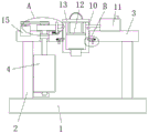
Fig. 1 is a schematic view of a front view structure provided by the present invention;
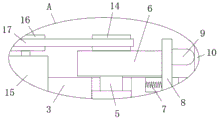
fig. 2 is a schematic structural view of part a of the present invention;
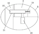
fig. 3 is a schematic structural diagram of part B of the present invention.
In the figure: 1. a base plate; 2. a support; 3. a top plate; 4. trimming rollers; 5. rotating the rod; 6. an eccentric wheel; 7. a spring; 8. moving the plate; 9. vibrating the block; 10. a filter cartridge; 11. a fan; 12. filtering with a screen; 13. a cover plate; 14. a first pulley; 15. a motor; 16. a second pulley; 17. a belt; 18. inserting a rod; 19. a pressure spring; 20. a handle; 21. and (4) a slot.
Detailed Description
The technical solutions in the embodiments of the present invention will be described clearly and completely with reference to the accompanying drawings in the embodiments of the present invention, and it is obvious that the described embodiments are only some embodiments of the present invention, not all embodiments.
Unless otherwise defined, technical or scientific terms used herein shall have the ordinary meaning as understood by one of ordinary skill in the art to which this invention belongs. The use of "first," "second," and similar terms in the description and in the claims does not indicate any order, quantity, or importance, but rather is used to distinguish one element from another. Also, the use of the terms "a" or "an" and the like do not denote a limitation of quantity, but rather denote the presence of at least one.
Referring to fig. 1-3, a furniture trimming device comprises a bottom plate 1, two brackets 2 are fixedly mounted on the top of the bottom plate 1, the same top plate 3 is fixedly mounted on the tops of the two brackets 2, a rotating hole is formed in the bottom of the top plate 3, a rotating rod 5 is rotatably mounted in the rotating hole, a connecting plate is fixedly mounted on one side of each bracket 2, a trimming roller 4 is rotatably mounted on the top of the connecting plate, the bottom end of the rotating rod 5 is fixedly mounted on the top of the trimming roller 4, an eccentric wheel 6 is fixedly mounted on the top end of the rotating rod 5, a spring groove is formed in the top of the top plate 3, a moving plate 8 is slidably mounted in the spring groove, one side of the moving plate 8 is in contact with the eccentric wheel 6, a spring 7 is fixedly connected to one side of the moving plate 8, one end, the mounting hole has been seted up at the top of roof 3, install filter box 10 in the mounting hole, the bottom fixed mounting of filter box 10 has the dust absorption pipe, apron 13 is installed at the top of filter box 10, the dead lever is installed to the bottom of apron 13, the bottom fixed mounting of dead lever has filter screen 12, filter screen 12 is installed in filter box 10, install two separation blades on the bottom inner wall of filter box 10, the top fixed mounting of roof 3 has fan 11, fan 11's air-supply line fixed mounting is in filter box 10.
In this embodiment, the top of eccentric wheel 6 is fixedly mounted with first band pulley 14, and the top of roof 3 is fixedly mounted with motor 15, and fixedly connected with second band pulley 16 on the output shaft of motor 15, second band pulley 16 and the meshing of first band pulley 14 have same belt 17, and motor 15 drives second band pulley 16 and rotates, and second band pulley 16 drives belt 17 and moves, and belt 17 drives first band pulley 14 and rotates.
In this embodiment, the downthehole fixed mounting that rotates has the bearing, and dwang 5 is fixed to be cup jointed at the inner circle of bearing, and dwang 5 is at the bearing internal rotation, can stabilize the position when dwang 5 rotates.
In this embodiment, slot 21 has all been seted up to the both sides of filter cartridge 10, the pressure spring groove has all been seted up on the both sides inner wall of mounting hole, equal slidable mounting has inserted bar 18 in two pressure spring inslots, inserted bar 18 is installed in the slot 21 that corresponds, the equal fixed mounting of one end that two inserted bars 18 kept away from each other has pressure spring 19, the equal fixed mounting of one end that two pressure springs 19 kept away from each other is on the inner wall in two pressure spring grooves that correspond, handle 20 drives the 18 removals of inserted bar that correspond, 18 roll-off slots 21 of inserted bar, can cancel filter cartridge 10's fixed restriction.
In this embodiment, the inner walls of the two compression spring grooves are provided with moving holes, moving blocks are slidably mounted in the two moving holes, one ends of the two moving blocks are fixedly mounted on the corresponding two insertion rods 18, and handles 20 are fixedly mounted at the other ends of the two moving blocks.
In this embodiment, a sliding groove is formed in the inner wall of the spring groove, a slider is fixedly mounted on one side of the moving plate 8, the slider is slidably mounted in the sliding groove, and the moving plate 8 is driven to slide in the sliding groove when moving, so that the moving position of the moving plate 8 can be stabilized.
In this embodiment, the motor 15 drives the second belt wheel 16 to rotate, the second belt wheel 16 drives the belt 17 to move, the belt 17 drives the first belt wheel 14 to rotate, so that the first belt wheel 14 drives the eccentric wheel 6 to rotate, the eccentric wheel 6 extrudes the movable plate 8, the movable plate 8 pulls the spring 7, the elastic action of the spring 7 can drive the movable plate 8 to reset, the movable plate 8 can drive the vibrating block 9 to repeatedly move, so that the vibrating block 9 repeatedly knocks the filter box 10, meanwhile, the eccentric wheel 6 drives the rotating rod 5 to rotate, the rotating rod 5 drives the trimming roller 4 to rotate, the wood plate is placed on the bottom plate 1, so that the trimming roller 4 trims the wood plate, the fan 11 drives the gas in the filter box 10 to flow, so that the two blocking pieces are opened, the dust suction pipe sucks the scraps generated by trimming into the filter box 10, the filter screen 12 can filter the scraps, and the vibrating block 9 can, two handles 20 are pulled, the corresponding inserted bar 18 is driven by the handles 20 to move, the inserted bar 18 slides out of the slot 21, the fixing limitation of the filter box 10 can be cancelled, and the scraps in the filter box 10 are conveniently cleaned.
The utility model discloses the technological progress that prior art obtained relatively is: the utility model discloses rational in infrastructure, convenient operation, this deburring equipment are convenient for restrain and collect the piece that grinds the production, can not influence operational environment.
Claims (6)
1. The furniture trimming device comprises a base plate (1) and is characterized in that two supports (2) are fixedly mounted at the top of the base plate (1), a same top plate (3) is fixedly mounted at the tops of the two supports (2), a rotating hole is formed in the bottom of the top plate (3), a rotating rod (5) is rotatably mounted in the rotating hole, a connecting plate is fixedly mounted at one side of each support (2), a trimming roller (4) is rotatably mounted at the top of the connecting plate, the bottom end of the rotating rod (5) is fixedly mounted at the top of the trimming roller (4), an eccentric wheel (6) is fixedly mounted at the top end of the rotating rod (5), a spring groove is formed in the top of the top plate (3), a movable plate (8) is slidably mounted in the spring groove, one side of the movable plate (8) is in contact with the eccentric wheel (6), and a, one end fixed mounting that movable plate (8) were kept away from in spring (7) is on one side inner wall of spring groove, and the opposite side fixed mounting of movable plate (8) has vibrating mass (9), and the mounting hole has been seted up at the top of roof (3), installs filter box (10) in the mounting hole, and the bottom fixed mounting of filter box (10) has the dust absorption pipe, apron (13) are installed at the top of filter box (10), and the dead lever is installed to the bottom of apron (13), and the bottom fixed mounting of dead lever has filter screen (12), and filter screen (12) are installed in filter box (10), install two separation blades on the bottom inner wall of filter box (10), the top fixed mounting of roof (3) has fan (11), and the air-supply line fixed mounting of fan (11) is in filter box (10).
2. A furniture trimming device according to claim 1, characterized in that a first belt pulley (14) is fixedly mounted on the top of the eccentric wheel (6), a motor (15) is fixedly mounted on the top of the top plate (3), a second belt pulley (16) is fixedly connected to the output shaft of the motor (15), and the second belt pulley (16) and the first belt pulley (14) are engaged with a same belt (17).
3. The furniture trimming device according to claim 1, wherein a bearing is fixedly arranged in the rotating hole, and the rotating rod (5) is fixedly sleeved on an inner ring of the bearing.
4. The furniture trimming device according to claim 1, wherein slots (21) are respectively formed in both sides of the filter box (10), compression spring grooves are respectively formed in inner walls of both sides of the mounting hole, insertion rods (18) are respectively slidably mounted in the two compression spring grooves, the insertion rods (18) are mounted in the corresponding slots (21), compression springs (19) are respectively fixedly mounted at ends of the two insertion rods (18) far away from each other, and ends of the two compression springs (19) far away from each other are respectively fixedly mounted on inner walls of the two compression spring grooves.
5. The furniture trimming device according to claim 4, wherein the inner walls of the two compression spring grooves are respectively provided with a moving hole, moving blocks are respectively and slidably mounted in the two moving holes, one end of each of the two moving blocks is fixedly mounted on the corresponding two insert rods (18), and the other end of each of the two moving blocks is fixedly mounted with a handle (20).
6. The trimming device for furniture according to claim 1, wherein the inner wall of the spring groove is provided with a sliding groove, one side of the moving plate (8) is fixedly provided with a sliding block, and the sliding block is slidably arranged in the sliding groove.
Priority Applications (1)
| Application Number | Priority Date | Filing Date | Title |
|---|---|---|---|
| CN202021513284.1U CN212946993U (en) | 2020-07-28 | 2020-07-28 | Furniture trimming device |
Applications Claiming Priority (1)
| Application Number | Priority Date | Filing Date | Title |
|---|---|---|---|
| CN202021513284.1U CN212946993U (en) | 2020-07-28 | 2020-07-28 | Furniture trimming device |
Publications (1)
| Publication Number | Publication Date |
|---|---|
| CN212946993U true CN212946993U (en) | 2021-04-13 |
Family
ID=75345491
Family Applications (1)
| Application Number | Title | Priority Date | Filing Date |
|---|---|---|---|
| CN202021513284.1U Expired - Fee Related CN212946993U (en) | 2020-07-28 | 2020-07-28 | Furniture trimming device |
Country Status (1)
| Country | Link |
|---|---|
| CN (1) | CN212946993U (en) |
-
2020
- 2020-07-28 CN CN202021513284.1U patent/CN212946993U/en not_active Expired - Fee Related
Similar Documents
| Publication | Publication Date | Title |
|---|---|---|
| CN111086041B (en) | Glass fiber board cutting device with glass fiber powder recovery function | |
| CN211615126U (en) | Dust removal getter device of floor drain production usefulness | |
| CN113635183A (en) | Grinding device for protection plate of generator | |
| CN111805338A (en) | Grinding device for machine case cutting edge | |
| CN209868155U (en) | Art litterbin processing is with deburring device that polishes | |
| CN212946993U (en) | Furniture trimming device | |
| CN218711706U (en) | Cutting machine for raincoat | |
| CN218254142U (en) | Numerical control lathe piece collection device | |
| CN115415615A (en) | Full-automatic electric automatic cutting machine | |
| CN113400374B (en) | Blade sectioning device for bioengineering | |
| CN213646930U (en) | Take dust extraction's wall polisher | |
| CN212635265U (en) | Trimmer for wood processing | |
| CN212241294U (en) | Cutting table for cutting plastic products | |
| CN209851015U (en) | Prevent cutting machine dust collector of jam | |
| CN113427338A (en) | Well lid production is with equipment of polishing | |
| CN211661693U (en) | Efficient is grinder for terrace coating | |
| CN215199453U (en) | Portable building foot line cutting device | |
| CN115890325A (en) | Rotatory grinding device with dust collecting box | |
| CN219380926U (en) | Tenoning equipment for woodwork processing | |
| CN219293136U (en) | High-bottom iron accessory welding table with fixed-point operation function | |
| CN215788529U (en) | Cutting device is used in production of row's of blanks shell | |
| CN218984225U (en) | Sealing plate trimming machine | |
| CN220660173U (en) | Automatic sharpening machine for diamond string bead rope saw | |
| CN220502915U (en) | Equidistant glass cutting device | |
| CN218927370U (en) | Polishing machine for shell processing |
Legal Events
| Date | Code | Title | Description |
|---|---|---|---|
| GR01 | Patent grant | ||
| GR01 | Patent grant | ||
| CF01 | Termination of patent right due to non-payment of annual fee |
Granted publication date: 20210413 Termination date: 20210728 |
|
| CF01 | Termination of patent right due to non-payment of annual fee |