CN212917439U - Rack for binding steel reinforcement framework on top plate of prefabricated box girder - Google Patents
Rack for binding steel reinforcement framework on top plate of prefabricated box girder Download PDFInfo
- Publication number
- CN212917439U CN212917439U CN202021619908.8U CN202021619908U CN212917439U CN 212917439 U CN212917439 U CN 212917439U CN 202021619908 U CN202021619908 U CN 202021619908U CN 212917439 U CN212917439 U CN 212917439U
- Authority
- CN
- China
- Prior art keywords
- reinforcing
- groove
- steel
- reinforcing bar
- channel
- Prior art date
- Legal status (The legal status is an assumption and is not a legal conclusion. Google has not performed a legal analysis and makes no representation as to the accuracy of the status listed.)
- Active
Links
Images


Landscapes
- Conveying And Assembling Of Building Elements In Situ (AREA)
Abstract
The utility model provides a prefabricated case roof beam steel reinforcement framework's of ligature rack, its includes two at least bracket unit, two reinforcing bar stop component that are parallel to each other, two at least first reinforcing bar supporting member and at least one second reinforcing bar supporting member that are parallel to each other. Every support unit is T type structure respectively, all support units arrange side by side and their projection coincidence, two reinforcing bar stop component are connected to two horizontal tip of each support unit respectively, make to form extension T type structure, each first reinforcing bar supporting member is located respectively between two reinforcing bar stop component and parallel with reinforcing bar stop component, each first reinforcing bar supporting member is connected to the support unit respectively, be provided with a plurality of reinforcing bar constant head tanks according to predetermined interval distribution on every first reinforcing bar supporting member, all reinforcing bar constant head tanks align in horizontal and vertical, the tank bottom of reinforcing bar constant head tank, reinforcing bar stop component's bottom surface and second reinforcing bar supporting member are all on same horizontal plane.
Description
Technical Field
The utility model belongs to the technical field of roof framework of steel reinforcement ligature, concretely relates to prefabricated case roof beam of ligature roof framework of steel reinforcement's rack.
Background
In the process of constructing basic building facilities such as highway bridges and the like, cement reinforcing bars are commonly used and are also an extremely important method for ensuring the strength of a concrete structure. In the bridge structure, because the load that the pontic will bear is bigger, so need arrange a large amount of reinforcing bars in load-bearing structure and guarantee reinforced concrete's structural strength, these a large amount of reinforcing bars need obtain reasonable reinforcing bar distribution rule after professional calculation and analysis, form the steel reinforcement skeleton through the ligature.
Generally, roof framework of steel reinforcement ligature is directly gone on in pier base top, carries out concrete placement afterwards, but, because of the span is great between the pier, it is extremely inconvenient to operate, and in operation process, because below bearing structure is less, and high altitude construction's reason causes the reinforcing bar interval inhomogeneous easily, and the location is inaccurate, the phenomenon such as warp more easily after the ligature, these all greatly drag the progress of construction slowly.
SUMMERY OF THE UTILITY MODEL
In order to solve the problem that exists among the prior art, the utility model provides a prefabricated case roof beam skeleton's of ligature rack, it includes: at least two bracket units, two parallel reinforcing steel bar limiting members, at least two parallel first reinforcing steel bar supporting members and at least one second reinforcing steel bar supporting member, wherein each bracket unit is respectively in a T-shaped structure, all the bracket units are arranged in parallel, the projections of the bracket units are overlapped, one reinforcing steel bar limiting member is connected to one end of each bracket unit in the transverse direction, the other reinforcing steel bar limiting member is connected to the other end of each bracket unit in the transverse direction, so that an elongated T-shaped structure is formed, each first reinforcing steel bar supporting member is respectively positioned between the two reinforcing steel bar limiting members and is parallel to the reinforcing steel bar limiting members, each first reinforcing steel bar supporting member is respectively connected to the bracket units, and a plurality of reinforcing steel bar positioning grooves distributed according to preset intervals are arranged on each first reinforcing steel bar supporting member, all the steel bar positioning grooves are aligned in the transverse direction and the longitudinal direction, and the groove bottoms of the steel bar positioning grooves, the bottom surfaces of the steel bar limiting members and the second steel bar supporting members are all on the same horizontal plane.
Preferably, each of the rack units includes a first support member, a second support member, a connecting member, a pillar, and two reinforcing bars.
Preferably, the first and second support members are respectively in an L-shaped structure, which are symmetrically located at both sides of the connection member and connected by the connection member, the upright is vertically connected to the connection member below the connection member, and the two reinforcing bars are crossed with each other and simultaneously connected with the first and second support members.
Preferably, the first support member comprises a horizontal first channel steel member and a vertical second channel steel member, wherein a first groove part with an upward concave part is arranged at the free end part of the first channel steel member and is used for supporting the steel bar limiting member.
Preferably, a steel plate member is welded at an upper end portion of the second channel member in parallel to a bottom surface of the second channel member such that the steel plate member and the second channel member together form a second groove part for supporting and positioning the first reinforcing bar support member.
Preferably, the second support member comprises a third horizontal channel steel piece and a fourth vertical channel steel piece, wherein a third groove part with an upward concave part is arranged at the free end part of the third channel steel piece and is used for supporting the steel bar limiting member.
Preferably, a steel plate member is welded at an upper end portion of the fourth channel member in parallel to a bottom surface of the fourth channel member such that the steel plate member and the fourth channel member together form a fourth groove part for supporting and positioning the first reinforcing bar support member.
Preferably, the first support member has a first channel for connecting the first channel and a first reinforcing rib groove for connecting the reinforcing rib welded to the upper end of the outer side wall of the second channel, and the second support member has a second channel for connecting the reinforcing rib welded to the lower end of the outer side wall of the second channel.
Preferably, the second support member is welded to the upper end of the third channel steel part outer side wall, the second connection member groove is used for connecting the connection member, the third reinforcing rib groove is used for supporting the reinforcing rib, and the fourth reinforcing rib groove is welded to the lower end of the fourth channel steel part outer side wall, and the fourth reinforcing rib groove is used for connecting the reinforcing rib.
Preferably, vertically downward connecting member pins are welded to both ends of the connecting member, respectively, and the two connecting member pins are inserted into the first connecting member groove and the second connecting member groove, respectively, to connect the first support member and the second support member.
Preferably, a post is arranged below the connecting member, and a U-shaped ring is welded to the upper end of the post for receiving and supporting the connecting member.
Preferably, a second reinforcing bar support member groove is welded to one side of the upper end of the upright post opposite to the U-shaped ring to support the second reinforcing bar support member.
Preferably, both ends of the reinforcing rib are provided with vertical downward reinforcing rib pins, the reinforcing rib pins at both ends of one of the reinforcing ribs are respectively inserted into the first reinforcing rib groove and the fourth reinforcing rib groove, and the reinforcing rib pins at both ends of the other reinforcing rib are respectively inserted into the third reinforcing rib groove and the second reinforcing rib groove.
Preferably, each of the reinforcing bar-retaining members is of a channel steel structure, and a plurality of reinforcing bar-retaining member pins are provided below a bottom surface of the channel steel for insertion into the first or third groove parts of the corresponding bracket units, thereby connecting the bracket units.
Preferably, each of the first reinforcing bar support members includes a channel member of a lower side portion and a plate member of an upper side portion, and the reinforcing bar positioning groove is provided on the plate member.
Preferably, a plurality of first reinforcing bar support member pins are provided under each of the first reinforcing bar support members, for being inserted into the second or fourth recess parts of the corresponding bracket units, thereby connecting the respective bracket units.
Preferably, the second reinforcing bar support member is a bar structure, and a plurality of vertically downward second reinforcing bar support member pins are provided thereunder for being inserted into the second reinforcing bar support member grooves of the corresponding bracket units, thereby connecting the respective bracket units.
Compared with the prior art, the utility model discloses a prefabricated case roof beam roof steel reinforcement framework's of ligature rack, the structure is comparatively simple, the cost is lower, because of it at first carries out the operation subaerial, it is more convenient and safe to make reinforcement's operation, and the reinforcing bar constant head tank on the first reinforcing bar supporting member has restricted the interval of reinforcing bar, reinforcing bar stop member has restricted the width of reinforcing bar, make the reinforcing bar interval more even, more laminate the numerical value of calculating in advance, can exert better effect, work efficiency also improves greatly simultaneously, can effectively accelerate the progress of construction, furthermore, but each position of this rack is split, it is more extensive to make its applicable scope, and preserve and transport more easily.
Drawings
Fig. 1 is a schematic structural view of an exemplary bench for binding a reinforcement cage of a top plate of a prefabricated box girder;
fig. 2 is an exemplary structural view of the reinforcing bar restraining member of fig. 1;
FIG. 3 is an exemplary structural schematic of the first support member of FIG. 1;
FIG. 4 is an exemplary structural schematic of the second support member of FIG. 1;
fig. 5 is an exemplary structural view of the first rebar support member of fig. 1;
FIG. 6 is an exemplary structural schematic of the connecting member of FIG. 1;
FIG. 7 is a schematic diagram of an exemplary construction of the reinforcing bar of FIG. 1;
fig. 8 is an exemplary structural schematic of the column of fig. 1.
Detailed Description
To facilitate a better understanding of the technical solutions of the present application, specific embodiments of the present application will be described in detail below with reference to the accompanying drawings.
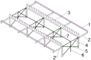
Fig. 1 shows the structure of an exemplary gantry of the present invention, which is generally composed of four support units, two mutually parallel bar-restraining members 1, two mutually parallel first bar-supporting members 3 and one second bar-supporting member 7. Adjacent bracket units are connected through a steel bar limiting member 1, a first steel bar supporting member 3 and a second steel bar supporting member 7, and the interval between the adjacent bracket units is preferably 2 m. It should be understood by those skilled in the art that the structure of the rack for binding the reinforcement cage of the top plate of the prefabricated box girder of the present invention is not limited thereto, and for example, the number of the bracket units may be two, three, five or more, the number of the first reinforcement supporting members 3 may be three or more, and the number of the second reinforcement supporting members 7 may be two or more.
As shown in fig. 1, each of the rack units has a T-shaped structure, all the rack units are arranged side by side and their projections coincide, wherein one reinforcement bar-retaining member 1 is connected to one end portion of each of the rack units in the lateral direction, and the other reinforcement bar-retaining member 1 is connected to the other end portion of each of the rack units in the lateral direction, so that all the rack units are connected to form an elongated T-shaped structure.
Each first rebar support member 3 is located between two rebar stop members 1, respectively, and is parallel with rebar stop members 1, and each first rebar support member 3 is connected to the bracket unit, respectively.
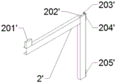
Each rack unit includes a first support member 2, a second support member 2 ', a connecting member 4 connecting the first support member 2 and the second support member 2', a pillar 6, and two reinforcing ribs 5.
As shown in fig. 1, 3 and 4, the first and second support members 2 and 2 'have L-shaped structures, respectively, which are symmetrically located at both sides of the connection member 4 and connected by the connection member 4, the column 6 is vertically connected to the connection member 4 below the connection member 4, and the two reinforcing bars 5 cross each other and are simultaneously connected with the first and second support members 2 and 2'.
The first support member 2 comprises a horizontal first channel steel member and a vertical second channel steel member. As shown in fig. 3, the free end of the first channel member is provided with a first groove part 201 having an upward concave portion for supporting the reinforcing bar-restraining member 1. The height of the first groove part 201 is preferably 5 cm. The steel plate member is welded at the upper end of the second channel member in parallel to the bottom surface of the second channel member so that the steel plate member and the second channel member together form a second channel part 202 for supporting and positioning the first rebar support member 3.
The upper end of the outer side wall of the second channel steel part in the first support member 2 is welded with a first connecting member groove 203 for connecting the connecting member 4 and a first reinforcing rib groove 204 for connecting the reinforcing rib 5, and the lower end of the outer side wall of the second channel steel part is welded with a second reinforcing rib groove 205 for connecting the reinforcing rib 5. The lengths of the first channel steel part and the second channel steel part in the first support member 2 are preferably 60cm, and the lengths of the first channel steel part and the second channel steel part can also be determined according to different requirements.
As shown in fig. 4, the second support member 2 ' includes a third horizontal channel steel part and a fourth vertical channel steel part, wherein the free end of the third channel steel part is provided with a third groove part 201 ' with an upward concave part for supporting the reinforcement bar-limiting member 1, and the height of the third groove part 201 ' is preferably 5 cm. The steel plate member is welded at the upper end of the fourth channel member in parallel to the bottom surface of the fourth channel member so that the steel plate member and the fourth channel member together form a fourth groove part 202' for supporting and positioning the first reinforcing bar support member 3.
The second connecting member groove 203 ' for connecting the connecting member 4 and the third bead groove 204 ' for connecting the bead 5 are welded to the upper end portion of the outer side wall of the fourth channel steel member in the second support member 2 '. The lower end part of the outer side wall of the fourth channel steel member is welded with a fourth reinforcing rib groove 205' for connecting a reinforcing rib 5. The length of the third channel steel part and the fourth channel steel part in the second support member 2' is preferably 60cm, and the length of the third channel steel part and the length of the fourth channel steel part can be determined according to different requirements.
As shown in fig. 6, the connecting member 4 has vertically downward connecting member pins 401 welded to both ends thereof, respectively, and the two connecting member pins 401 are inserted into the first and second connecting member grooves 203 and 203 ' to connect the first and second support members 2 and 2 ', respectively, the connecting member pins 401 having diameters smaller than inner diameters of the first and second connecting member grooves 203 and 203 ', respectively. When the length of the connecting member 4 exceeds 2m, it is preferable to provide one column 6 per interval 2 m.
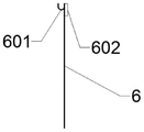
As shown in fig. 8, a U-shaped ring 601 is welded to the upper end of the column 6 for receiving and supporting the connection member 4, the opening diameter of the U-shaped ring 601 is larger than that of the connection member 4, and a second reinforcing bar support member groove 602 is welded to the upper end of the column 6 at a side opposite to the U-shaped ring 601 for supporting the second reinforcing bar support member 7. The height of the upright post 6 is preferably 60cm, and the height of the upright post 6 can be determined according to different requirements.
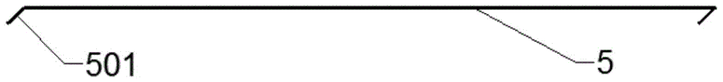
As shown in fig. 7, the reinforcing bars 5 are provided at both ends thereof with vertically downward reinforcing bar pins 501, wherein the reinforcing bar pins 501 at both ends of one reinforcing bar 5 are respectively inserted into the first reinforcing bar groove 204 and the fourth reinforcing bar groove 205 ', and the reinforcing bar pins 501 at both ends of the other reinforcing bar 5 are respectively inserted into the third reinforcing bar groove 204' and the second reinforcing bar groove 205.
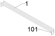
Each reinforcing steel bar limiting member 1 can be an integral channel steel with a preset length, or can be formed by splicing a plurality of channel steels. When the reinforcing steel bar limiting member 1 is of an integrated structure, a plurality of reinforcing steel bar limiting member pins are welded below each channel steel and are used for being inserted into the first groove part 201 or the third groove part 201' of the corresponding support unit, so that the reinforcing steel bar limiting member 1 is used for connecting the support units.
When the reinforcing bar stop member 1 is formed by splicing a plurality of channel steels, two reinforcing bar stop member pins 101 are welded below the bottom surface of each channel steel respectively, as shown in fig. 2. The reinforcing steel bar limiting member pin 101 of one channel steel is respectively inserted into the first groove parts 201 of the two adjacent first supporting members 2, and the reinforcing steel bar limiting member pin 101 of the other channel steel is respectively inserted into the third groove parts 201' of the two adjacent second supporting members 2, so that the two adjacent bracket units are connected. Every first recess part 201 or third recess part 201' can hold two reinforcing bar stop member pins 101 for the channel-section steel can link together the support unit firmly when the concatenation forms reinforcing bar stop member 1, and then ensures that the roof framework of reinforcement size that the ligature was accomplished is more rigorous.
Every first steel bar support member 3 includes the channel-section steel of downside and the board component 301 of upside, and on board component 301 was located to reinforcing bar constant head tank 302, the channel-section steel of downside can increase first steel bar support member 3's rigidity, makes it straighter more, is difficult to produce the deformation bending. The first reinforcing bar support member 3 may be an integral structure having a predetermined length, or may be composed of a plurality of support member units.
When the first reinforcing bar support members 3 are of an integral structure, a plurality of first reinforcing bar support member pins facing downward are welded to the channel steel for being inserted into the second groove part 202 or the fourth groove part 202' of the corresponding bracket unit, so that the first reinforcing bar support members 3 connect the respective bracket units.
When the first rebar support member 3 is composed of a plurality of support member units, a first rebar support member pin 303 facing downwards is welded to each of two ends of the channel steel of each support member unit, and the two first rebar support member pins 303 are inserted into the second groove part 202 or the fourth groove part 202' of the two adjacent bracket units respectively. Each second or fourth channel part 202 or 202 'is configured to receive two first rebar support member pins 303 simultaneously so that two adjacent support member units can be tightly connected together by the second or fourth channel part 202 or 202' while the bracket units are secured together, thereby ensuring more accurate spacing between the finished roof rebar. Each first reinforcing bar support member 3 preferably has a length of 2 m.
The plate member 301 of the first reinforcing bar supporting member 3 is provided with a plurality of reinforcing bar positioning slots 302 distributed according to a predetermined interval, the predetermined interval may be the same or different, and the reinforcing bar positioning slots 302 with different sizes may be combined according to different requirements. All the reinforcement positioning grooves 302 are aligned in the lateral and longitudinal directions, the groove bottom of the reinforcement positioning groove 302 is preferably 5cm high with respect to the horizontally placed plane, and the depth of the reinforcement positioning groove 302 is equal to or greater than the height of the stirrup.
The second reinforcing bar support member 7 may be a metal rod having a predetermined length, or may be formed by splicing a plurality of metal rods. When the second reinforcing bar support member 7 is of an integral structure, a plurality of second reinforcing bar support member pins, which are vertically downward, are welded under the metal rod for insertion into the second reinforcing bar support member grooves 602 of the corresponding bracket units, so that the second reinforcing bar support member 7 connects the respective bracket units.
When the second reinforcing bar support member 7 is formed by splicing a plurality of metal bars, two second reinforcing bar member pins which are vertically downward are welded below each metal bar and are inserted into the second reinforcing bar support member grooves 602 of two adjacent bracket units, and each second reinforcing bar support member groove 602 is configured to accommodate two second reinforcing bar support member pins simultaneously, so that the metal bars can stably connect all the bracket units while being connected to form the second reinforcing bar support member 7. The second steel bar support member 7 is used for supporting the transversely placed stirrups, so that the stirrups cannot deform and sag due to overlong span, and the straightness of the stirrups is affected.
The tank bottom of the steel bar positioning groove 302 and the second steel bar supporting member 7 are located on the same horizontal plane, so that the stirrups placed in the steel bar positioning groove 302 can be sufficiently supported, and the stirrups are prevented from deforming and sagging. The lateral part of reinforcing bar stop component 1 can block the excessive displacement of stirrup, ensures the parallel and level of stirrup, can not take place the skew.
The first support member 2 and the second support member 2 'of each set of bracket units are connected by inserting the connecting member pin 401 on the connecting member 4 into the connecting member groove 203 and the connecting member groove 203', and meanwhile, the reinforcing bar pin 501 at the upper end of one reinforcing bar 5 is inserted into the first reinforcing bar groove 204 of the first support member 2, and the reinforcing bar pin 501 at the lower end is inserted into the second reinforcing bar groove 205 'of the second support member 2'; the upper end bead pin 501 of the other bead 5 is inserted into the first bead groove 204 'of the second support member 2', and the lower end bead pin 501 is inserted into the second bead groove 205 of the first support member 2, for reinforcing the set of rack units.
The utility model discloses a prefabricated case roof beam roof steel reinforcement framework's of ligature rack, the structure is comparatively simple, the cost is lower, because of it at first works subaerial, it is more convenient and safety to make steel reinforcement's operation, and the reinforcing bar constant head tank on the first steel bar support component has restricted the interval of reinforcing bar, reinforcing bar stop member has restricted the width of reinforcing bar, make the reinforcing bar interval more even, the numerical value that calculates in advance more laminates, can exert better effect, work efficiency also improves greatly simultaneously, can effectively accelerate the progress of construction, furthermore, but each position split of this rack comes, make its applicable scope more extensive, and preserve and transport more easily.
The applicant of the present invention has made detailed description and description of the embodiments of the present invention with reference to the drawings, but those skilled in the art should understand that the above embodiments are only the preferred embodiments of the present invention, and the detailed description is only for helping the reader to better understand the spirit of the present invention, and not for the limitation of the protection scope of the present invention, on the contrary, any improvement or modification made based on the spirit of the present invention should fall within the protection scope of the present invention.
Claims (9)
1. The utility model provides a prefabricated case roof beam top slab steel reinforcement framework's of ligature rack, it includes: at least two support units are characterized in that: the rack also comprises two parallel reinforcing steel bar limiting members (1), at least two parallel first reinforcing steel bar supporting members (3) and at least one second reinforcing steel bar supporting member (7),
each support unit is of a T-shaped structure, all the support units are arranged in parallel, the projections of the support units are overlapped,
one of the reinforcing bar-retaining members (1) is connected to one end portion of each of the bracket units in the lateral direction, and the other reinforcing bar-retaining member (1) is connected to the other end portion of each of the bracket units in the lateral direction, so that an elongated T-shaped structure is formed,
each first reinforcing steel bar supporting member (3) is respectively positioned between the two reinforcing steel bar limiting members (1) and is parallel to the reinforcing steel bar limiting members (1), each first reinforcing steel bar supporting member (3) is respectively connected to the bracket unit,
each first steel bar supporting component (3) is provided with a plurality of steel bar positioning grooves (302) distributed according to a preset interval, all the steel bar positioning grooves (302) are aligned in the transverse direction and the longitudinal direction, and the groove bottom of each steel bar positioning groove (302), the bottom surface of each steel bar limiting component (1) and the second steel bar supporting component (7) are all on the same horizontal plane.
2. The rack of prefabricated box girder roof slab framework of reinforcement of ligature of claim 1, characterized in that: each of the support units comprises a first support member (2), a second support member (2'), a connecting member (4), a column (6) and two reinforcing bars (5),
the first support member (2) and the second support member (2 ') are respectively in an L-shaped structure, are symmetrically positioned at both sides of the connecting member (4) and are connected through the connecting member (4), the upright post (6) is vertically connected to the connecting member (4) below the connecting member (4), and the two reinforcing ribs (5) are crossed with each other and are simultaneously connected with the first support member (2) and the second support member (2').
3. The rack of prefabricated box girder roof slab framework of reinforcement of ligature of claim 2, characterized in that:
the first supporting member (2) comprises a horizontal first channel steel piece and a vertical second channel steel piece, wherein the free end part of the first channel steel piece is provided with a first groove part (201) with an upward concave part for supporting the steel bar limiting member (1),
welding a steel plate member in parallel to the bottom surface of the second channel piece at the upper end of the second channel piece such that the steel plate member and the second channel piece together form a second channel part (202) for supporting and positioning the first reinforcement support member (3),
the second supporting member (2 ') comprises a third horizontal channel steel piece and a fourth vertical channel steel piece, wherein the free end part of the third channel steel piece is provided with a third groove part (201') with an upward concave part for supporting the reinforcing steel bar limiting member (1),
and welding a steel plate member at the upper end part of the fourth channel steel part in a manner of being parallel to the bottom surface of the fourth channel steel part, so that the steel plate member and the fourth channel steel part together form a fourth groove part (202') for supporting and positioning the first reinforcing steel bar supporting member (3).
4. The rack of prefabricated box girder roof slab framework of reinforcement of ligature of claim 3, characterized in that: the upper end part of the outer side wall of the second channel steel part in the first supporting member (2) is welded with a first connecting member groove (203) for connecting the connecting member (4) and a first reinforcing rib groove (204) for connecting the reinforcing rib (5), the lower end part of the outer side wall of the second channel steel part is welded with a second reinforcing rib groove (205) for connecting the reinforcing rib (5),
the upper end part of the outer side wall of the fourth channel steel part of the second supporting member (2 ') is welded with a second connecting member groove (203') for connecting the connecting member (4) and a third reinforcing rib groove (204 ') for connecting the reinforcing rib (5), and the lower end part of the outer side wall of the fourth channel steel part is welded with a fourth reinforcing rib groove (205') for connecting the reinforcing rib (5).
5. The rack of prefabricated box girder roof slab framework of reinforcement of ligature of claim 4, characterized in that: both ends of the connection member (4) are respectively welded with a vertically downward connection member pin (401), the two connection member pins (401) are respectively inserted into the first connection member groove (203) and the second connection member groove (203 ') to connect the first support member (2) and the second support member (2'),
an upright post (6) is arranged below the connecting member (4), a U-shaped ring (601) is welded at the upper end of the upright post (6) and used for receiving and supporting the connecting member (4),
and a second steel bar supporting member groove (602) is welded at one side of the upper end of the upright post (6) relative to the U-shaped ring (601) and is used for supporting the second steel bar supporting member (7).
6. The rack of prefabricated box girder roof slab framework of reinforcement of ligature of claim 4, characterized in that: the reinforcing rib structure is characterized in that vertical downward reinforcing rib pins (501) are arranged at two ends of each reinforcing rib (5), the reinforcing rib pins (501) at the two ends of each reinforcing rib (5) are respectively inserted into the first reinforcing rib groove (204) and the fourth reinforcing rib groove (205 '), and the reinforcing rib pins (501) at the two ends of each reinforcing rib (5) are respectively inserted into the third reinforcing rib groove (204') and the second reinforcing rib groove (205).
7. The rack of prefabricated box girder roof slab framework of reinforcement of ligature of claim 3, characterized in that: each reinforcing steel bar limiting member (1) is of a channel steel structure, and a plurality of reinforcing steel bar limiting member pins (101) are arranged below the bottom surface of the channel steel and are used for being inserted into the first groove part (201) or the third groove part (201') of the corresponding support unit so as to connect the support units.
8. The rack of prefabricated box girder roof slab framework of reinforcement of ligature of claim 3, characterized in that: each of the first reinforcing bar support members (3) includes a channel member of a lower side portion and a plate member (301) of an upper side portion, the reinforcing bar positioning grooves (302) are provided on the plate member (301),
a plurality of first reinforcing bar support member pins (303) are provided under each of the first reinforcing bar support members (3) for insertion into the second groove part (202) or the fourth groove part (202') of the corresponding bracket unit, thereby connecting the respective bracket units.
9. The rack of prefabricated box girder roof slab framework of reinforcement of ligature of claim 6, characterized in that: the second reinforcing bar support members (7) are of a bar structure, and a plurality of vertically downward second reinforcing bar support member pins are provided thereunder for insertion into the second reinforcing bar support member grooves (602) of the corresponding bracket units, thereby coupling the respective bracket units.
Priority Applications (1)
| Application Number | Priority Date | Filing Date | Title |
|---|---|---|---|
| CN202021619908.8U CN212917439U (en) | 2020-08-06 | 2020-08-06 | Rack for binding steel reinforcement framework on top plate of prefabricated box girder |
Applications Claiming Priority (1)
| Application Number | Priority Date | Filing Date | Title |
|---|---|---|---|
| CN202021619908.8U CN212917439U (en) | 2020-08-06 | 2020-08-06 | Rack for binding steel reinforcement framework on top plate of prefabricated box girder |
Publications (1)
| Publication Number | Publication Date |
|---|---|
| CN212917439U true CN212917439U (en) | 2021-04-09 |
Family
ID=75335813
Family Applications (1)
| Application Number | Title | Priority Date | Filing Date |
|---|---|---|---|
| CN202021619908.8U Active CN212917439U (en) | 2020-08-06 | 2020-08-06 | Rack for binding steel reinforcement framework on top plate of prefabricated box girder |
Country Status (1)
| Country | Link |
|---|---|
| CN (1) | CN212917439U (en) |
-
2020
- 2020-08-06 CN CN202021619908.8U patent/CN212917439U/en active Active
Similar Documents
| Publication | Publication Date | Title |
|---|---|---|
| CN210659276U (en) | Template positioning device for thickness of shear wall and concrete protective layer | |
| CN217144340U (en) | Vertical reinforcement bed-jig of prefabricated box culvert | |
| CN113882712A (en) | Temporary support reinforcing method for large-scale suspension type steel structure construction | |
| CN212917439U (en) | Rack for binding steel reinforcement framework on top plate of prefabricated box girder | |
| CN214055807U (en) | Push-pull type hollow slab reinforcement jig frame capable of being accurately positioned | |
| CN212129839U (en) | Steel pipe reinforcing column structure | |
| CN217991463U (en) | Temporary fixing device for welding processing of lattice column | |
| CN114054647A (en) | Rack for binding steel reinforcement framework on top plate of prefabricated box girder | |
| CN207392768U (en) | A kind of Multi-section slippage device in irregular large-span space structure of constructing | |
| CN212919870U (en) | Rack for binding prefabricated box girder bottom plate web steel reinforcement frameworks | |
| CN213925893U (en) | Jig frame and pier stud construction device | |
| CN213135623U (en) | A rack for welding prefabricated box girder bottom plate web stirrup semi-manufactured goods | |
| CN212554393U (en) | Steel bar binding clamping fixture for prefabricated box girder | |
| CN113417478A (en) | Prefabricated post guiding device that takes one's place | |
| CN217299891U (en) | Frame roof beam reinforcing bar setting tool | |
| CN111890549A (en) | Rack for binding prefabricated box girder bottom plate web steel reinforcement frameworks | |
| CN210263641U (en) | Beam column node steel bar guide cage | |
| CN219451284U (en) | Auxiliary support system of split heads for large-section beam reinforcement construction | |
| JP6854652B2 (en) | Reinforcing bar assembly method and rebar assembly jig | |
| CN216665059U (en) | T-shaped beam steel bar positioning device | |
| CN217831682U (en) | Prefabricated case roof beam roof reinforcement shaping pedestal | |
| CN217733756U (en) | Positioning jig frame of cast-in-situ beam framework | |
| CN217782594U (en) | Iron reinforcement braced system on super thick bottom plate that can install fast | |
| CN215848856U (en) | Binding jig frame for prefabricated box girder steel reinforcement framework | |
| CN214939185U (en) | Prefabricated stand |
Legal Events
| Date | Code | Title | Description |
|---|---|---|---|
| GR01 | Patent grant | ||
| GR01 | Patent grant |