CN212916036U - Powder coating grinds machine - Google Patents
Powder coating grinds machine Download PDFInfo
- Publication number
- CN212916036U CN212916036U CN202020957764.0U CN202020957764U CN212916036U CN 212916036 U CN212916036 U CN 212916036U CN 202020957764 U CN202020957764 U CN 202020957764U CN 212916036 U CN212916036 U CN 212916036U
- Authority
- CN
- China
- Prior art keywords
- box
- fixedly connected
- motor
- front side
- powder coating
- Prior art date
- Legal status (The legal status is an assumption and is not a legal conclusion. Google has not performed a legal analysis and makes no representation as to the accuracy of the status listed.)
- Active
Links
Images


Abstract
The utility model discloses a powder coating grinds machine, the power distribution box comprises a box body, down fixedly connected with baffle and filter in proper order from last in the inner chamber of box, the relief hole has all been seted up to left front side in baffle bottom and rear side, the first motor of top fixedly connected with on box right side, the pivot of first motor runs through to the inner chamber and the fixedly connected with bull stick of box, the left end of bull stick and the inner wall swing joint of box, the fixed surface of bull stick is connected with broken pole, broken pole is located the top of baffle, the left top swing joint of box inner chamber has the threaded rod. The utility model discloses possess and smash the function and grind the efficient advantage, solved current powder coating and ground the machine, in the use, because single structure, can't smash the powder coating of great piece, lead to influencing subsequent grinding work, and can not relapse high-efficient grinding to powder coating to the problem of grinding machine suitability has been reduced.
Description
Technical Field
The utility model relates to a powder coating technical field specifically is a powder coating grinds machine.
Background
The powder paint is a solid powder synthetic resin paint composed of solid resin, pigment, filler and assistant, and is different from ordinary solvent paint and water paint in that its dispersion medium is not solvent and water but air, and it has the features of no solvent pollution, 100% filming and low energy consumption.
The existing powder coating grinding machine cannot smash larger powder coating due to single structure in the use process, so that subsequent grinding work is influenced, and repeated high-efficiency grinding can not be performed on the powder coating, so that the applicability of the grinding machine is reduced.
SUMMERY OF THE UTILITY MODEL
An object of the utility model is to provide a powder coating grinds machine possesses and smashes the function and grind the efficient advantage, has solved current powder coating and has ground the machine, in the use, because single structure can't smash the powder coating of great piece, leads to influencing subsequent grinding work, and can not relapse high-efficient the grinding to powder coating to the problem of grinding machine suitability has been reduced.
In order to achieve the above object, the utility model provides a following technical scheme: a powder coating grinding machine comprises a box body, wherein a partition plate and a filter plate are fixedly connected to the inner cavity of the box body from top to bottom in sequence, discharge holes are formed in the front side and the rear side of the left side of the bottom of the partition plate, a first motor is fixedly connected to the top of the right side of the box body, a rotating shaft of the first motor penetrates through the inner cavity of the box body and is fixedly connected with a rotating rod, the left end of the rotating rod is movably connected with the inner wall of the box body, a crushing rod is fixedly connected to the surface of the rotating rod and is positioned at the top of the partition plate, a threaded rod is movably connected to the top of the left side of the inner cavity of the box body, a second motor is fixedly connected to the right side of the box body, a rotating shaft of the second motor penetrates through the inner cavity of the box body and is in threaded connection with the threaded rod, a threaded sleeve is sleeved on, the bottom end of the electric telescopic rod is fixedly connected with a second connecting plate, supporting plates are fixedly connected to the front side and the rear side of the two sides of the bottom of the second connecting plate, a grinding roller is movably connected to one side, opposite to the supporting plates, of the supporting plates, the grinding roller is located at the top of the filtering plate, the right side of the top of the box body is communicated with a feeding pipe, and a material receiving box is placed at the bottom of the inner cavity of the box body.
Preferably, the bottom of the front side of the box body is movably connected with a box door through a hinge, and the front side of the box door is fixedly connected with a handle.
Preferably, the front side fixedly connected with access panel of box, the four corners of access panel front side all runs through and is provided with the bolt, the rear end of bolt run through to the rear side of access panel and with box threaded connection.
Preferably, the equal fixedly connected with guide block in front side and the rear side of first connecting plate, the guide way has all been seted up to the front side and the rear side of box inner chamber, the guide block is kept away from the inner chamber that one side of first connecting plate extended to the guide way, guide block and guide way swing joint.
Preferably, the top fixedly connected with controller of box front side, the controller respectively with first motor, second motor and electric telescopic handle electric connection.
Compared with the prior art, the beneficial effects of the utility model are as follows:
1. the utility model discloses a box, a separation plate, the filter, the relief hole, first motor, the bull stick, the broken pole, the threaded rod, the second motor, the thread bush, first connecting plate, electric telescopic handle, the second connecting plate, the cooperation of extension board and grinding roller, possess and smash the function and grind the efficient advantage, the current powder coating grinds the machine has been solved, in the use, because single structure, can't smash the powder coating of great piece, lead to influencing subsequent grinding work, and can not relapse high efficiency to powder coating and grind, thereby the problem of grinding machine suitability has been reduced.
2. The utility model discloses a set up the filter, can filter thinner powder coating, through setting up first motor, bull stick and crushing pole, can carry out the breakage to the powder coating of great piece, thereby promote subsequent grinding efficiency, through setting up threaded rod and thread bush, make grinding roller remove about can, through setting up electric telescopic handle, make grinding roller can reciprocate, through setting up extension board and grinding roller, can carry out high-efficient grinding to powder coating, through setting up material receiving box, be convenient for connect the powder coating who accomplishes grinding and get, through setting up access panel and bolt, the staff of being convenient for overhauls the part, through setting up guide block and guide way, make first connecting plate remove the removal in-process more steady about.
Drawings
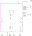
FIG. 1 is a schematic sectional view of the structure of the present invention;
FIG. 2 is a front view of the structure of the present invention;
FIG. 3 is a schematic right sectional view of the partial structure of the present invention;
fig. 4 is a schematic left view of the local structure of the present invention.
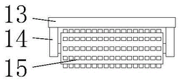
In the figure: the automatic grinding device comprises a box body 1, a partition plate 2, a filter plate 3, a discharge hole 4, a first motor 5, a rotating rod 6, a crushing rod 7, a threaded rod 8, a second motor 9, a threaded sleeve 10, a first connecting plate 11, an electric telescopic rod 12, a second connecting plate 13, a supporting plate 14, a grinding roller 15, a feeding pipe 16, a material receiving box 17, a box door 18, a maintenance plate 19, a bolt 20, a guide block 21, a guide groove 22 and a controller 23.
Detailed Description
The technical solutions in the embodiments of the present invention will be described clearly and completely with reference to the accompanying drawings in the embodiments of the present invention, and it is obvious that the described embodiments are only some embodiments of the present invention, not all embodiments. Based on the embodiments in the present invention, all other embodiments obtained by a person skilled in the art without creative work belong to the protection scope of the present invention.
In the description of the present invention, it should be noted that the terms "upper", "lower", "inner", "outer", "front end", "rear end", "both ends", "one end", "the other end", and the like indicate orientations or positional relationships based on the orientations or positional relationships shown in the drawings, and are only for convenience of description and simplification of description, but do not indicate or imply that the device or element to be referred must have a specific orientation, be constructed in a specific orientation, and be operated, and thus, should not be construed as limiting the present invention. Furthermore, the terms "first" and "second" are used for descriptive purposes only and are not to be construed as indicating or implying relative importance.
In the description of the present invention, it is to be noted that, unless otherwise explicitly specified or limited, the terms "mounted", "provided", "connected", and the like are to be construed broadly, such as "connected", which may be fixedly connected, detachably connected, or integrally connected; can be mechanically or electrically connected; they may be connected directly or indirectly through intervening media, or they may be interconnected between two elements. The specific meaning of the above terms in the present invention can be understood in specific cases to those skilled in the art.
The utility model discloses a box 1, baffle 2, filter 3, relief hole 4, first motor 5, bull stick 6, broken pole 7, threaded rod 8, second motor 9, thread bush 10, first connecting plate 11, electric telescopic handle 12, second connecting plate 13, extension board 14, grinding roller 15, inlet pipe 16, material receiving box 17, chamber door 18, access panel 19, bolt 20, guide block 21, guide way 22 and controller 23 part are the parts that universal standard spare or technical field personnel know, its structure and principle all can learn through the technical manual or learn through conventional experimental method for this technical personnel.
Referring to fig. 1-4, a powder coating grinder comprises a box body 1, a box door 18 is movably connected to the bottom of the front side of the box body 1 through a hinge, a handle is fixedly connected to the front side of the box door 18, an inspection board 19 is fixedly connected to the front side of the box body 1, bolts 20 are arranged at four corners of the front side of the inspection board 19 in a penetrating manner, the rear ends of the bolts 20 penetrate to the rear side of the inspection board 19 and are in threaded connection with the box body 1, the inspection board 19 and the bolts 20 are arranged to facilitate workers to inspect parts, a controller 23 is fixedly connected to the top of the front side of the box body 1, the controller 23 is respectively and electrically connected with a first motor 5, a second motor 9 and an electric telescopic rod 12, a partition plate 2 and a filter plate 3 are fixedly connected to the inner cavity of the box body 1 from top to bottom, and the filter plate 3 can filter relatively fine powder coating, the left front side and the left rear side of the bottom of the baffle plate 2 are both provided with a discharge hole 4, the top part of the right side of the box body 1 is fixedly connected with a first motor 5, the rotating shaft of the first motor 5 penetrates through the inner cavity of the box body 1 and is fixedly connected with a rotating rod 6, the left end of the rotating rod 6 is movably connected with the inner wall of the box body 1, the surface of the rotating rod 6 is fixedly connected with a crushing rod 7, the powder coating with larger blocks can be crushed by arranging the first motor 5, the rotating rod 6 and the crushing rod 7, so as to improve the subsequent grinding efficiency, the crushing rod 7 is positioned at the top part of the baffle plate 2, the left top part of the inner cavity of the box body 1 is movably connected with a threaded rod 8, the right side of the box body 1 is fixedly connected with a second motor 9, the rotating shaft of the second motor 9 penetrates through the inner cavity of the box body 1 and is in, the grinding roller 15 can move left and right by arranging the threaded rod 8 and the threaded sleeve 10, the bottom of the threaded sleeve 10 is fixedly connected with a first connecting plate 11, the front side and the rear side of the first connecting plate 11 are fixedly connected with guide blocks 21, the front side and the rear side of the inner cavity of the box body 1 are respectively provided with a guide groove 22, one side of each guide block 21, far away from the first connecting plate 11, extends to the inner cavity of the guide groove 22, the guide blocks 21 are movably connected with the guide grooves 22, the first connecting plate 11 is more stable in the left and right moving process by arranging the guide blocks 21 and the guide grooves 22, the bottom of the first connecting plate 11 is fixedly connected with an electric telescopic rod 12, the grinding roller 15 can move up and down by arranging the electric telescopic rod 12, the bottom end of the electric telescopic rod 12 is fixedly connected with a second connecting plate 13, and the front side and the rear side of two sides of the bottom of the second, the grinding roll 15 is movably connected to one side opposite to the support plate 14, the powder coating can be efficiently ground by arranging the support plate 14 and the grinding roll 15, the grinding roll 15 is positioned at the top of the filter plate 3, the right side of the top of the box body 1 is communicated with the feeding pipe 16, the material receiving box 17 is arranged at the bottom of the inner cavity of the box body 1, the ground powder coating can be conveniently received by arranging the material receiving box 17, and the grinding function and the grinding efficiency can be realized by matching the box body 1, the partition plate 2, the filter plate 3, the discharge hole 4, the first motor 5, the rotating rod 6, the crushing rod 7, the threaded rod 8, the second motor 9, the threaded sleeve 10, the first connecting plate 11, the electric telescopic rod 12, the second connecting plate 13, the support plate 14 and the grinding roll 15, so that the existing powder coating grinding machine is solved, and in the use process, the powder coating of a larger piece cannot be crushed due to, the subsequent grinding work is influenced, and the powder coating cannot be repeatedly and efficiently ground, so that the applicability of the grinding machine is reduced.
When the powder coating grinding device is used, a power supply is connected, powder coating to be ground is thrown into an inner cavity of a box body 1 through a feeding pipe 16, then a controller 23 controls a first motor 5 to operate, a rotating shaft of the first motor 5 drives a rotating rod 6 to rotate, the rotating rod 6 drives a crushing rod 7 to rotate, the crushing rod 7 crushes larger powder coating, the crushed powder coating falls to the top of a filter plate 3 through a discharge hole 4, then a controller 23 controls an electric telescopic rod 12 to extend, the electric telescopic rod 12 drives a second connecting plate 13 to move downwards, the second connecting plate 13 drives the supporting plate 14 and a grinding roller 15 to move downwards, the grinding roller 15 is in contact with the filter plate 3, then the controller 23 controls a second motor 9 to operate, a rotating shaft of the second motor 9 drives a threaded rod 8 to rotate, the threaded rod 8 is in threaded connection with a threaded sleeve 10 to enable the threaded sleeve 10 to move towards the left side, the threaded sleeve 10 drives the first connecting plate 11 and the electric telescopic rod, electric telescopic handle 12 drives second connecting plate 13 and removes to the left side, second connecting plate 13 drives grinding roll 15 and removes to the left side, grinding roll 15 grinds powder coating, thinner powder coating drops to the inner chamber of material receiving box 17 through filter 3, then controller 23 control second motor 9 pivot reverses, under the effect of second motor 9 pivot reversal, grinding roll 15 removes to the right side, thereby grind powder coating repeatedly, after the grinding is accomplished, open chamber door 18, take out material receiving box 17, collect powder coating.
In summary, the following steps: this powder coating grinds machine, through box 1, baffle 2, filter 3, relief hole 4, first motor 5, bull stick 6, broken pole 7, threaded rod 8, second motor 9, thread bush 10, first connecting plate 11, electric telescopic handle 12, second connecting plate 13, extension board 14 and grinding roller 15's cooperation, the current powder coating grinds machine has been solved, in the use, because single structure, can't smash the powder coating of great piece, lead to influencing subsequent grinding work, and can not relapse high efficiency to powder coating and grind, thereby the problem of grinding machine suitability has been reduced.
Although embodiments of the present invention have been shown and described, it will be appreciated by those skilled in the art that changes, modifications, substitutions and alterations can be made in these embodiments without departing from the principles and spirit of the invention, the scope of which is defined in the appended claims and their equivalents.
Claims (5)
1. A powder coating material grinds machine, includes box (1), its characterized in that: the inner cavity of the box body (1) is fixedly connected with a partition plate (2) and a filter plate (3) from top to bottom in sequence, a discharge hole (4) is formed in the front side and the rear side of the left side of the bottom of the partition plate (2), a first motor (5) is fixedly connected to the top of the right side of the box body (1), a rotating shaft of the first motor (5) penetrates through the inner cavity of the box body (1) and is fixedly connected with a rotating rod (6), the left end of the rotating rod (6) is movably connected with the inner wall of the box body (1), a breaking rod (7) is fixedly connected to the surface of the rotating rod (6), the breaking rod (7) is positioned at the top of the partition plate (2), a threaded rod (8) is movably connected to the top of the left side of the inner cavity of the box body (1), a second motor (9) is fixedly connected to the right side of the box body (1), and a rotating shaft of the second motor (, the surface thread bush of threaded rod (8) is equipped with thread bush (10), the first connecting plate (11) of bottom fixedly connected with of thread bush (10), the bottom fixedly connected with electric telescopic handle (12) of first connecting plate (11), the bottom fixedly connected with second connecting plate (13) of electric telescopic handle (12), the equal fixedly connected with extension board (14) in front side and the rear side of second connecting plate (13) bottom both sides, one side swing joint that extension board (14) is relative has grinding roller (15), grinding roller (15) are located the top of filter (3), the right side intercommunication at box (1) top has inlet pipe (16), material receiving box (17) have been placed to the bottom of box (1) inner chamber.
2. The powder paint grinder of claim 1, wherein: the bottom of the front side of the box body (1) is movably connected with a box door (18) through a hinge, and the front side of the box door (18) is fixedly connected with a handle.
3. The powder paint grinder of claim 1, wherein: the front side fixedly connected with maintenance board (19) of box (1), the four corners of maintenance board (19) front side all runs through and is provided with bolt (20), the rear end of bolt (20) run through to the rear side of maintenance board (19) and with box (1) threaded connection.
4. The powder paint grinder of claim 1, wherein: the equal fixedly connected with guide block (21) of front side and rear side of first connecting plate (11), guide way (22) have all been seted up to the front side and the rear side of box (1) inner chamber, one side that first connecting plate (11) were kept away from in guide block (21) extends to the inner chamber of guide way (22), guide block (21) and guide way (22) swing joint.
5. The powder paint grinder of claim 1, wherein: the top fixedly connected with controller (23) of box (1) front side, controller (23) respectively with first motor (5), second motor (9) and electric telescopic handle (12) electric connection.
Priority Applications (1)
| Application Number | Priority Date | Filing Date | Title |
|---|---|---|---|
| CN202020957764.0U CN212916036U (en) | 2020-05-29 | 2020-05-29 | Powder coating grinds machine |
Applications Claiming Priority (1)
| Application Number | Priority Date | Filing Date | Title |
|---|---|---|---|
| CN202020957764.0U CN212916036U (en) | 2020-05-29 | 2020-05-29 | Powder coating grinds machine |
Publications (1)
| Publication Number | Publication Date |
|---|---|
| CN212916036U true CN212916036U (en) | 2021-04-09 |
Family
ID=75318822
Family Applications (1)
| Application Number | Title | Priority Date | Filing Date |
|---|---|---|---|
| CN202020957764.0U Active CN212916036U (en) | 2020-05-29 | 2020-05-29 | Powder coating grinds machine |
Country Status (1)
| Country | Link |
|---|---|
| CN (1) | CN212916036U (en) |
Cited By (1)
| Publication number | Priority date | Publication date | Assignee | Title |
|---|---|---|---|---|
| CN113182045A (en) * | 2021-05-08 | 2021-07-30 | 安徽元昌建设工程有限公司 | Building screening sand device |
-
2020
- 2020-05-29 CN CN202020957764.0U patent/CN212916036U/en active Active
Cited By (2)
| Publication number | Priority date | Publication date | Assignee | Title |
|---|---|---|---|---|
| CN113182045A (en) * | 2021-05-08 | 2021-07-30 | 安徽元昌建设工程有限公司 | Building screening sand device |
| CN113182045B (en) * | 2021-05-08 | 2024-03-22 | 安徽元昌建设工程有限公司 | Building sand screening device |
Similar Documents
| Publication | Publication Date | Title |
|---|---|---|
| CN211992034U (en) | Chip removal collecting vat for machine tool machining | |
| CN213914238U (en) | Vibration grinding and conveying device for soil remediation | |
| CN212916036U (en) | Powder coating grinds machine | |
| CN211887117U (en) | Paint raw material pulverizer | |
| CN211463440U (en) | Food detects uses preprocessing device | |
| CN211279349U (en) | Recovery reducing mechanism of rubber leftover bits | |
| CN215918988U (en) | Disintegrating slag strikes recovery type wind-powered electricity generation flange production with forging platform | |
| CN212597052U (en) | Powder coating separator | |
| CN211709785U (en) | Abandonment plastic recovery unit | |
| CN211134129U (en) | Prevent graphite dust leakage's grinder for graphite processing | |
| CN213102605U (en) | Waste material reducing mechanism for construction | |
| CN212632986U (en) | Dust absorption device of bottle blowing section pulverizer | |
| CN212331533U (en) | Environment-friendly waste plastic crushing and recycling equipment | |
| CN216260964U (en) | Crushing and grinding equipment based on coating production | |
| CN213417535U (en) | Zebra crossing line drawing device | |
| CN209140552U (en) | A kind of accumulator plate grinding edge-neatening apparatus | |
| CN211660083U (en) | Be used for building concrete production with smashing device | |
| CN220386700U (en) | Sand mill is used in pigment processing convenient to clearance | |
| CN213078609U (en) | Grinding machine with screening function | |
| CN220196266U (en) | Waste sand treatment equipment | |
| CN213726934U (en) | Crushing apparatus for chemical raw material production | |
| CN212596186U (en) | Green's construction is with smashing recovery plant | |
| CN213377049U (en) | Continuous crushing and converting device for anode material of waste lithium battery | |
| CN214159911U (en) | Carbonized rice hull raw material pulverizer | |
| CN214288633U (en) | Making wine raw materials rubbing crusher |
Legal Events
| Date | Code | Title | Description |
|---|---|---|---|
| GR01 | Patent grant | ||
| GR01 | Patent grant |