CN212913290U - Ligature forceps with detachable bent forceps head - Google Patents
Ligature forceps with detachable bent forceps head Download PDFInfo
- Publication number
- CN212913290U CN212913290U CN202020349035.7U CN202020349035U CN212913290U CN 212913290 U CN212913290 U CN 212913290U CN 202020349035 U CN202020349035 U CN 202020349035U CN 212913290 U CN212913290 U CN 212913290U
- Authority
- CN
- China
- Prior art keywords
- forceps
- pincers
- binding clip
- detachable
- handle
- Prior art date
- Legal status (The legal status is an assumption and is not a legal conclusion. Google has not performed a legal analysis and makes no representation as to the accuracy of the status listed.)
- Expired - Fee Related
Links
- 210000000080 chela (arthropods) Anatomy 0.000 claims abstract description 98
- 238000007789 sealing Methods 0.000 claims description 19
- 238000005452 bending Methods 0.000 claims description 11
- 210000004204 blood vessel Anatomy 0.000 abstract description 6
- 238000000034 method Methods 0.000 abstract description 2
- 238000002674 endoscopic surgery Methods 0.000 description 4
- 230000004048 modification Effects 0.000 description 2
- 238000012986 modification Methods 0.000 description 2
- 230000003796 beauty Effects 0.000 description 1
- 230000000694 effects Effects 0.000 description 1
- 238000002324 minimally invasive surgery Methods 0.000 description 1
- 238000001356 surgical procedure Methods 0.000 description 1
- 230000000007 visual effect Effects 0.000 description 1
Images


Abstract
The utility model relates to a crooked detachable ligature pincers of binding clip, including the pincers handle, the tong pipe, the runner can be dismantled binding clip and interior pole, and the pincers handle setting is in the one end of tong pipe, and the runner setting is on the tong pipe, and the other end of tong pipe is provided with can dismantle the binding clip, and interior pole setting is intraductal at the pincers, and the one end of interior pole is provided with second magnet, can dismantle the binding clip including interior pincers seat, outer pincers seat, left side pincers mouth and right pincers mouth are connected with outer pincers seat, and outer pincers seat, left side pincers head and right pincers head pass through the spout round pin and are connected with interior pincers seat, and the one end of interior pincers seat is provided with first magnet, and the one end of dismantling the binding clip is provided with binding clip connecting portion. The jaw part can be bent, the problem of the unable ligature of some angle tissue or blood vessel in the operation has been solved, the utility model discloses a can make the operator in the operation in-process more nimble ligature blood vessel, just the utility model is simple in operation, the operator can very easy use the utility model discloses, patient is safer in the operation.
Description
Technical Field
The utility model relates to a medical instrument, concretely relates to crooked detachable ligature pincers of binding clip.
Background
With the rapid development of concepts such as precise medical treatment, rapid rehabilitation and minimally invasive surgery, the endoscopic surgery has partially or completely replaced the traditional open surgery in many fields, and through the continuous progress of nearly 20 years, the endoscopic surgery has the advantages of small wound, light pain, few complications, beauty, short hospitalization time and the like, and is rapidly a unique item of surgical operation. The development of the endoscopic surgery is not free from innovation and progress of surgical instruments, wherein an automatic ligator for an endoscope is an indispensable 'weapon' in the endoscopic surgery, the automatic ligator for clinical use at present mainly takes Hem-o-lok produced by Tailifu in the United states, and the automatic ligator produced by domestic manufacturers has very similar structure, function, usage and the like. The ligation clip is mainly used for ligating blood vessels or tissues in operations, and is widely used in operations such as laparoscope, thoracoscope and pelvic endoscope. Although the automatic ligator is simple to use and reliable in effect, the ligation clamp of the automatic ligator is straight and cannot be bent, and for some tissues or blood vessels with angles, the automatic ligator cannot be used for vertical ligation or the locking buckle of the ligation clamp cannot be clearly displayed due to the fact that the visual field of the ligation clamp is blocked, so that inconvenience and potential safety hazards are brought to an operation.
Disclosure of Invention
In order to solve the technical problem, the utility model provides a ligature forceps with detachable bending forceps head, which comprises a forceps handle, a forceps tube, a rotating wheel, a detachable forceps head and an inner rod, wherein the forceps handle comprises a left forceps handle and a right forceps handle, the left forceps handle is connected with the right forceps handle through a screw, the forceps handle is arranged at one end of the forceps tube, the rotating wheel is arranged on the forceps tube, the other end of the forceps tube is provided with a forceps tube connecting part connected with the detachable forceps head, the inner rod is arranged in the forceps tube, one end of the inner rod close to the forceps handle is provided with a push rod, the other end of the inner rod is provided with a second magnet, the second magnet is fixedly connected with the forceps tube through a sealing sleeve, the detachable forceps head comprises an inner forceps base, an outer forceps base, a left forceps mouth and a right forceps mouth, the left forceps mouth and the right forceps mouth are connected with the outer base through a shaft pin, the outer forceps base is fixedly arranged on the detachable forceps head, and the outer tong seat, the left tong head and the right tong head are connected with the inner tong seat through sliding groove pins, one end of the inner tong seat is provided with a first magnet connected with a second magnet, and one end of the dismounting tong head connected with the tong pipe is provided with a tong head connecting part.
Furthermore, a push rod pin is arranged on the push rod, and the left forceps handle is connected with the push rod pin.
Further, the fixed cover that is provided with on the interior pole, be provided with the pressure spring between fixed cover and the seal cover, the one end that the pressure spring is close to fixed cover is contradicted in fixed cover surface, and the one end that fixed cover was kept away from to the pressure spring is contradicted in the seal cover.
Furthermore, the angle of bending the binding clip of the detachable binding clip is 0-90 degrees.
The utility model has the advantages of, the binding clip part can be crooked, has solved the problem of the unable ligature of some angle tissue or blood vessel in the operation, the utility model discloses a can make the operator at the ligature blood vessel that the operation in-process is more nimble, just the utility model discloses an easy operation, operator can very easy use the utility model discloses, patient is safer in the operation.
Drawings
The accompanying drawings, which are incorporated in and constitute a part of this application, are included to provide a further understanding of the invention, and are incorporated in and constitute a part of this specification. In the drawings:
FIG. 1 is a schematic view of the present invention;
FIG. 2 is a schematic view of the internal structure of the present invention;
FIG. 3 is a schematic view of the detachable binding clip with 0 degree binding clip of the present invention;
FIG. 4 is a schematic view of a detachable binding clip with a 30 degree binding clip according to the present invention;
FIG. 5 is a schematic view of the detachable binding clip with 45 degree binding clip of the present invention;
FIG. 6 is a schematic view of the detachable binding clip with 60 ° binding clip of the present invention;
fig. 7 is a schematic view of the detachable binding clip with 90 ° binding clip of the present invention.
Detailed Description
It should be noted that the embodiments and features of the embodiments in the present application may be combined with each other without conflict. The present invention will be described in detail below with reference to the accompanying drawings in conjunction with embodiments.
In order to make the technical solutions better understood by those skilled in the art, the technical solutions in the embodiments of the present application will be clearly and completely described below with reference to the drawings in the embodiments of the present application, and it is obvious that the described embodiments are only partial embodiments of the present application, but not all embodiments. All other embodiments, which can be derived by a person skilled in the art from the embodiments given herein without making any creative effort, shall fall within the protection scope of the present application.
The first embodiment is as follows:
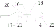
as shown in figures 1-3, a pair of ligation pliers with detachable bending pliers heads comprises a pliers handle 1, a pliers tube 2, a rotating wheel 3, a detachable pliers head 4 and an inner rod 5, wherein the pliers handle 1 is arranged at one end of the pliers tube 2, the pliers handle 1 comprises a left pliers handle 7 and a right pliers handle 8, the left pliers handle 7 is connected with the right pliers handle 8 through a screw 9, one end of the pliers tube 2 connected with the detachable pliers head 4 is provided with a pliers tube connecting sheet 23, the rotating wheel 3 is fixedly arranged on the pliers tube 2, the inner rod 5 is arranged in the pliers tube 2, one end of the inner rod 5 close to the pliers handle 1 is provided with a push rod 6, the push rod 6 is provided with a push rod pin 10, the push rod pin 10 is connected with the left pliers handle 7, one side of the inner rod 5 connected with the detachable pliers head 4 is provided with a second magnet 13, the second magnet 13 is provided with a sealing sleeve 14, the second magnet 13 is fixedly connected with the pliers tube 2 through, a pressure spring 12 is arranged between the sealing sleeve 14 and the fixing sleeve 11, one end of the pressure spring 12 close to the fixing sleeve 11 is abutted against the surface of the fixing sleeve 11, and one end of the pressure spring 12 far away from the fixing sleeve 11 is abutted against the sealing sleeve 14
Can dismantle binding clip 4 includes interior pincers seat 16, outer pincers seat 17, left side pincers mouth 20 and right pincers mouth 21, the one end that can dismantle binding clip 4 is provided with left pincers mouth 20 and right pincers mouth 21, outer pincers seat 17 is fixed to be set up on can dismantling binding clip 4, left side pincers mouth 20 and right pincers mouth 21 set up on outer pincers seat 17 through pivot 19, fixed sliding groove round pin 18 that is provided with on interior pincers seat 16, and left side pincers mouth 20, right side pincers mouth 21 and outer pincers seat 17 are connected with interior pincers seat 16 through sliding groove round pin 18, the one end of interior pincers seat 16 is provided with first magnet 15 of being connected with second magnet 13, the one end that can dismantle binding clip 4 and be connected with tong pipe 2 is provided with binding clip connection piece 22, and can dismantle binding clip 4 and be connected with tong pipe 2 through binding clip connection piece 22.
The angle of the jaw of the detachable binding clip 4 is 0 deg.
Example two:
as shown in fig. 1, 2 and 4, a pair of ligation pliers with detachable bending pliers heads comprises a pliers handle 1, a pliers tube 2, a rotating wheel 3, a detachable pliers head 4 and an inner rod 5, wherein the pliers handle 1 is arranged at one end of the pliers tube 2, the pliers handle 1 comprises a left pliers handle 7 and a right pliers handle 8, the left pliers handle 7 is connected with the right pliers handle 8 through a screw 9, a pliers tube connecting sheet 23 is arranged at one end of the pliers tube 2 connected with the detachable pliers head 4, the rotating wheel 3 is fixedly arranged on the pliers tube 2, the inner rod 5 is arranged in the pliers tube 2, a push rod 6 is arranged at one end of the inner rod 5 close to the pliers handle 1, a push rod pin 10 is arranged on the push rod 6, the push rod pin 10 is connected with the left pliers handle 7, a second magnet 13 is arranged at one side of the inner rod 5 connected with the detachable pliers head 4, a sealing sleeve 14 is arranged on the second magnet 13, the second magnet 13 is fixedly connected with the pliers tube 2, and a pressure spring 12 is arranged between the sealing sleeve 14 and the fixing sleeve 11, one end of the pressure spring 12 close to the fixing sleeve 11 is abutted against the surface of the fixing sleeve 11, and one end of the pressure spring 12 far away from the fixing sleeve 11 is abutted against the sealing sleeve 14.
Can dismantle binding clip 4 includes interior pincers seat 16, outer pincers seat 17, left side pincers mouth 20 and right pincers mouth 21, the one end that can dismantle binding clip 4 is provided with left pincers mouth 20 and right pincers mouth 21, outer pincers seat 17 is fixed to be set up on can dismantling binding clip 4, left side pincers mouth 20 and right pincers mouth 21 set up on outer pincers seat 17 through pivot 19, fixed sliding groove round pin 18 that is provided with on interior pincers seat 16, and left side pincers mouth 20, right side pincers mouth 21 and outer pincers seat 17 are connected with interior pincers seat 16 through sliding groove round pin 18, the one end of interior pincers seat 16 is provided with first magnet 15 of being connected with second magnet 13, the one end that can dismantle binding clip 4 and be connected with tong pipe 2 is provided with binding clip connection piece 22, and can dismantle binding clip 4 and be connected with tong pipe 2 through binding clip connection piece 22.
The angle of the jaw of the detachable binding clip 4 is 30 degrees.
Example three:
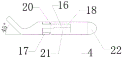
as shown in fig. 1, 2 and 5, a pair of ligation pliers with detachable bending pliers heads comprises a pliers handle 1, a pliers tube 2, a rotating wheel 3, a detachable pliers head 4 and an inner rod 5, wherein the pliers handle 1 is arranged at one end of the pliers tube 2, the pliers handle 1 comprises a left pliers handle 7 and a right pliers handle 8, the left pliers handle 7 is connected with the right pliers handle 8 through a screw 9, a pliers tube connecting sheet 23 is arranged at one end of the pliers tube 2 connected with the detachable pliers head 4, the rotating wheel 3 is fixedly arranged on the pliers tube 2, the inner rod 5 is arranged in the pliers tube 2, a push rod 6 is arranged at one end of the inner rod 5 close to the pliers handle 1, a push rod pin 10 is arranged on the push rod 6, the push rod pin 10 is connected with the left pliers handle 7, a second magnet 13 is arranged at one side of the inner rod 5 connected with the detachable pliers head 4, a sealing sleeve 14 is arranged on the second magnet 13, the second magnet 13 is fixedly connected with the pliers tube 2, and a pressure spring 12 is arranged between the sealing sleeve 14 and the fixing sleeve 11, one end of the pressure spring 12 close to the fixing sleeve 11 is abutted against the surface of the fixing sleeve 11, and one end of the pressure spring 12 far away from the fixing sleeve 11 is abutted against the sealing sleeve 14.
Can dismantle binding clip 4 includes interior pincers seat 16, outer pincers seat 17, left side pincers mouth 20 and right pincers mouth 21, the one end that can dismantle binding clip 4 is provided with left pincers mouth 20 and right pincers mouth 21, outer pincers seat 17 is fixed to be set up on can dismantling binding clip 4, left side pincers mouth 20 and right pincers mouth 21 set up on outer pincers seat 17 through pivot 19, fixed sliding groove round pin 18 that is provided with on interior pincers seat 16, and left side pincers mouth 20, right side pincers mouth 21 and outer pincers seat 17 are connected with interior pincers seat 16 through sliding groove round pin 18, the one end of interior pincers seat 16 is provided with first magnet 15 of being connected with second magnet 13, the one end that can dismantle binding clip 4 and be connected with tong pipe 2 is provided with binding clip connection piece 22, and can dismantle binding clip 4 and be connected with tong pipe 2 through binding clip connection piece 22.
The angle of the jaw of the detachable binding clip 4 is 45 degrees.
Example four:
as shown in fig. 1, 2 and 6, a pair of ligation pliers with detachable bending pliers heads comprises a pliers handle 1, a pliers tube 2, a rotating wheel 3, a detachable pliers head 4 and an inner rod 5, wherein the pliers handle 1 is arranged at one end of the pliers tube 2, the pliers handle 1 comprises a left pliers handle 7 and a right pliers handle 8, the left pliers handle 7 is connected with the right pliers handle 8 through a screw 9, a pliers tube connecting sheet 23 is arranged at one end of the pliers tube 2 connected with the detachable pliers head 5, the rotating wheel 3 is fixedly arranged on the pliers tube 2, the inner rod 5 is arranged in the pliers tube 2, a push rod 6 is arranged at one end of the inner rod 5 close to the pliers handle 1, a push rod pin 10 is arranged on the push rod 6, the push rod pin 10 is connected with the left pliers handle 7, a second magnet 13 is arranged at one side of the inner rod 5 connected with the detachable pliers head 4, a sealing sleeve 14 is arranged on the second magnet 13, the second magnet 13 is fixedly connected with the pliers tube 2, and a pressure spring 12 is arranged between the sealing sleeve 14 and the fixing sleeve 11, one end of the pressure spring 12 close to the fixing sleeve 11 is abutted against the surface of the fixing sleeve 11, and one end of the pressure spring 12 far away from the fixing sleeve 11 is abutted against the sealing sleeve 14.
Can dismantle binding clip 4 includes interior pincers seat 16, outer pincers seat 17, left side pincers mouth 20 and right pincers mouth 21, the one end that can dismantle binding clip 4 is provided with left pincers mouth 20 and right pincers mouth 21, outer pincers seat 17 is fixed to be set up on can dismantling binding clip 4, left side pincers mouth 20 and right pincers mouth 21 set up on outer pincers seat 17 through pivot 19, fixed sliding groove round pin 18 that is provided with on interior pincers seat 16, and left side pincers mouth 20, right side pincers mouth 21 and outer pincers seat 17 are connected with interior pincers seat 16 through sliding groove round pin 18, the one end of interior pincers seat 16 is provided with first magnet 15 of being connected with second magnet 13, the one end that can dismantle binding clip 4 and be connected with tong pipe 2 is provided with binding clip connection piece 22, and can dismantle binding clip 4 and be connected with tong pipe 2 through binding clip connection piece 22.
The angle of the jaw of the detachable binding clip 4 is 60 °.
Example five:
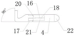
as shown in fig. 1, 2 and 7, a pair of ligation pliers with detachable bending pliers heads comprises a pliers handle 1, a pliers tube 2, a rotating wheel 3, a detachable pliers head 4 and an inner rod 5, wherein the pliers handle 1 is arranged at one end of the pliers tube 2, the pliers handle 1 comprises a left pliers handle 7 and a right pliers handle 8, the left pliers handle 7 is connected with the right pliers handle 8 through a screw 9, a pliers tube connecting sheet 23 is arranged at one end of the pliers tube 2 connected with the detachable pliers head 4, the rotating wheel 3 is fixedly arranged on the pliers tube 2, the inner rod 5 is arranged in the pliers tube 2, a push rod 6 is arranged at one end of the inner rod 5 close to the pliers handle 1, a push rod pin 10 is arranged on the push rod 6, the push rod pin 10 is connected with the left pliers handle 7, a second magnet 13 is arranged at one side of the inner rod 5 connected with the detachable pliers head 4, a sealing sleeve 14 is arranged on the second magnet 13, the second magnet 13 is fixedly connected with the pliers tube 2, and a pressure spring 12 is arranged between the sealing sleeve 14 and the fixing sleeve 11, one end of the pressure spring 12 close to the fixing sleeve 11 is abutted against the surface of the fixing sleeve 11, and one end of the pressure spring 12 far away from the fixing sleeve 11 is abutted against the sealing sleeve 14.
Can dismantle binding clip 4 includes interior pincers seat 16, outer pincers seat 17, left side pincers mouth 20 and right pincers mouth 21, the one end that can dismantle binding clip 4 is provided with left pincers mouth 20 and right pincers mouth 21, outer pincers seat 17 is fixed to be set up on can dismantling binding clip 4, left side pincers mouth 20 and right pincers mouth 21 set up on outer pincers seat 17 through pivot 19, fixed sliding groove round pin 18 that is provided with on interior pincers seat 16, and left side pincers mouth 20, right side pincers mouth 21 and outer pincers seat 17 are connected with interior pincers seat 16 through sliding groove round pin 18, the one end of interior pincers seat 16 is provided with first magnet 15 of being connected with second magnet 13, the one end that can dismantle binding clip 4 and be connected with tong pipe 2 is provided with binding clip connection piece 22, and can dismantle binding clip 4 and be connected with tong pipe 2 through binding clip connection piece 22.
The angle of the jaw of the detachable binding clip 4 is 90 degrees.
Before use, the detachable binding clip 4 with different angles is prepared, and when the detachable binding clip is required to be used, the first magnet 15 in the detachable binding clip 4 is attracted with the second magnet 13 in the binding clip 2 by utilizing the principle of magnetic force, so that the detachable binding clip 4 is connected with the binding clip 2; when the detachable binding clip 4 with different angles needs to be replaced, the detachable binding clip 4 can be pulled out, and the external force is larger than the magnetic force.
The above description is only a preferred embodiment of the present invention and is not intended to limit the present invention, and various modifications and changes may be made by those skilled in the art. Any modification, equivalent replacement, or improvement made within the spirit and principle of the present invention should be included in the protection scope of the present invention.
Claims (4)
1. The utility model provides a crooked detachable ligature pincers of binding clip, includes pincers handle (1), pincers pipe (2), runner (3), can dismantle binding clip (4) and interior pole (5), its characterized in that: the forceps handle (1) comprises a left forceps handle (7) and a right forceps handle (8), the left forceps handle (7) is connected with the right forceps handle (8) through a screw (9), the forceps handle (1) is arranged at one end of the forceps tube (2), the rotating wheel (3) is arranged on the forceps tube (2), the other end of the forceps tube (2) is provided with a forceps tube connecting part (23) connected with a detachable forceps head (4), the inner rod (5) is arranged in the forceps tube (2), one end of the inner rod (5) close to the forceps handle (1) is provided with a push rod (6), the other end of the inner rod (5) is provided with a second magnet (13), the second magnet (13) is fixedly connected with the forceps tube (2) through a sealing sleeve (14), the detachable forceps head (4) comprises an inner forceps base (16), an outer forceps base (17), a left forceps mouth (20) and a right forceps mouth (21), and the left forceps mouth (20) and the right forceps mouth (21) are connected with the outer forceps base (17) through a shaft pin (19), and outer tong seat (17) are fixed to be set up on can dismantling binding clip (4), are fixed on interior tong seat (16) to be provided with spout round pin (18), and outer tong seat (17), left tong mouth (20) and right tong mouth (21) are connected with interior tong seat (16) through spout round pin (18), and the one end of interior tong seat (16) is provided with first magnet (15) of being connected with second magnet (13), and the one end of dismantling binding clip (4) and being connected of tong pipe (2) is provided with binding clip connecting portion (22).
2. The ligature forceps with the detachable bending forceps head as claimed in claim 1, wherein a push rod pin (10) is arranged on the push rod (6), and the left forceps handle (7) is connected with the push rod pin (10).
3. The ligature forceps with the detachable bending forceps head as claimed in claim 1, wherein a fixing sleeve (11) is fixedly arranged on the inner rod (5), a pressure spring (12) is arranged between the fixing sleeve (11) and the sealing sleeve (14), one end of the pressure spring (12) close to the fixing sleeve (11) abuts against the surface of the fixing sleeve (11), and one end of the pressure spring (12) far away from the fixing sleeve (11) abuts against the sealing sleeve (14).
4. The ligature forceps with the detachable bending forceps head as claimed in claim 1, wherein the angle of bending of the forceps head of the detachable forceps head (4) is 0-90 °.
Priority Applications (1)
| Application Number | Priority Date | Filing Date | Title |
|---|---|---|---|
| CN202020349035.7U CN212913290U (en) | 2020-03-19 | 2020-03-19 | Ligature forceps with detachable bent forceps head |
Applications Claiming Priority (1)
| Application Number | Priority Date | Filing Date | Title |
|---|---|---|---|
| CN202020349035.7U CN212913290U (en) | 2020-03-19 | 2020-03-19 | Ligature forceps with detachable bent forceps head |
Publications (1)
| Publication Number | Publication Date |
|---|---|
| CN212913290U true CN212913290U (en) | 2021-04-09 |
Family
ID=75297431
Family Applications (1)
| Application Number | Title | Priority Date | Filing Date |
|---|---|---|---|
| CN202020349035.7U Expired - Fee Related CN212913290U (en) | 2020-03-19 | 2020-03-19 | Ligature forceps with detachable bent forceps head |
Country Status (1)
| Country | Link |
|---|---|
| CN (1) | CN212913290U (en) |
-
2020
- 2020-03-19 CN CN202020349035.7U patent/CN212913290U/en not_active Expired - Fee Related
Similar Documents
| Publication | Publication Date | Title |
|---|---|---|
| JP5701491B2 (en) | Laparoscopic instruments and related surgical methods | |
| US5443479A (en) | Surgical forceps | |
| US5368600A (en) | Steerable bulldog clamp applier | |
| AU2002320128B2 (en) | Surgical clip | |
| US5897565A (en) | Releasable, surgical clamp | |
| AU2012261484A1 (en) | Jaw closure mechanism for a surgical clip applier | |
| JP2001505810A (en) | Surgical tool with flexible shaft | |
| JP2007511248A5 (en) | ||
| CN110292411A (en) | A kind of tissue folder closes device | |
| WO1997020508A1 (en) | Surgical instrument | |
| CN212913290U (en) | Ligature forceps with detachable bent forceps head | |
| US20090182350A1 (en) | Instrucment and method for treatment of hemorrhoids | |
| CN111166419A (en) | Ligature forceps with detachable bent forceps head | |
| JP5806852B2 (en) | Clip operation forceps, clip attachment / detachment forceps and clip, and endoscopic surgical instrument set composed of these | |
| CN214632265U (en) | Titanium clamp for endoscope with bendable clamp head | |
| CN201968770U (en) | Functional laparoscopic surgery forceps | |
| CN210019534U (en) | Clamping device of minimally invasive abdominal surgery equipment | |
| CN201968758U (en) | Surgical clamp | |
| CN112790831A (en) | Titanium clamp for endoscope with bendable clamp head | |
| CN206463029U (en) | Chain type blocks pincers | |
| CN208693391U (en) | Handle pincers and mammary gland snag | |
| CN220213005U (en) | Titanium clamp capable of adjusting clamping angle for endoscope | |
| CN206365916U (en) | Three-pawl type stone dislodger | |
| CN203564306U (en) | Minimally invasive knot tying forceps | |
| CN209347183U (en) | A kind of throat foreign body forceps |
Legal Events
| Date | Code | Title | Description |
|---|---|---|---|
| GR01 | Patent grant | ||
| GR01 | Patent grant | ||
| CF01 | Termination of patent right due to non-payment of annual fee |
Granted publication date: 20210409 |
|
| CF01 | Termination of patent right due to non-payment of annual fee |