CN212887425U - Bolt fastening device - Google Patents
Bolt fastening device Download PDFInfo
- Publication number
- CN212887425U CN212887425U CN202021461240.9U CN202021461240U CN212887425U CN 212887425 U CN212887425 U CN 212887425U CN 202021461240 U CN202021461240 U CN 202021461240U CN 212887425 U CN212887425 U CN 212887425U
- Authority
- CN
- China
- Prior art keywords
- bolt
- servo motor
- fastening device
- sleeve
- mount pad
- Prior art date
- Legal status (The legal status is an assumption and is not a legal conclusion. Google has not performed a legal analysis and makes no representation as to the accuracy of the status listed.)
- Expired - Fee Related
Links
Images

Landscapes
- Details Of Spanners, Wrenches, And Screw Drivers And Accessories (AREA)
Abstract
The utility model discloses a bolt fastening device, sleeve pipe including the bottom opening setting, the inside slip of sheathed tube is provided with the mount pad, the sheathed tube side is equipped with the spout, the side of mount pad is equipped with the clamp plate with spout sliding connection, the bottom of mount pad is equipped with the bumper shock absorber, the bottom of bumper shock absorber is equipped with the motor cabinet, the bottom of motor cabinet is equipped with servo motor, be equipped with fastening device on servo motor's the output shaft, the sheathed tube side is equipped with the sleeve, and telescopic top is equipped with the handle, and the top of handle is equipped with the switch block, and the sheathed tube top is equipped with the protection box, and the inside of protection box is equipped with the group battery. This bolt-up device can be according to the size quick replacement allen key of bolt to can fasten the bolt under multiple environment, need not to bow and visit into inside the lathe, can use manpower sparingly, improve work efficiency, easy operation, convenient to use.
Description
Technical Field
The utility model relates to the technical field of mechanical equipment, specifically be a bolt fastening device.
Background
A bolt is a cylindrical threaded fastener fitted with a nut. A fastener consisting of a head part and a screw (a cylinder with external threads) needs to be matched with a nut and is used for fastening and connecting two parts with through holes.
When various mechanical devices are installed, bolts are used for fixing, such as a street lamp base and a lathe inner component. When fixing the bolt, because the bolt position difference needs artifical bowing even the upper part of the body enters into the lathe inside and fixes, the operation is inconvenient, and artifical fastening speed is slow moreover, and work efficiency is low.
SUMMERY OF THE UTILITY MODEL
The to-be-solved technical problem of the utility model is to overcome current defect, provide a bolt fastening device, can be according to the hexagon socket wrench in the size quick replacement of bolt to can fasten the bolt under multiple environment, need not to bow and visit into inside the lathe, can use manpower sparingly, improve work efficiency, easy operation, convenient to use can effectively solve the problem in the background art.
In order to achieve the above object, the utility model provides a following technical scheme: the utility model provides a bolt fastening device, includes the sleeve pipe that the bottom opening set up, sheathed tube inside slides and is provided with the mount pad, sheathed tube side is equipped with the spout, the side of mount pad be equipped with spout sliding connection's clamp plate, the bottom of mount pad is equipped with the bumper shock absorber, the bottom of bumper shock absorber is equipped with the motor cabinet, the bottom of motor cabinet is equipped with servo motor, be equipped with fastening device on servo motor's the output shaft.
The telescopic side is equipped with the sleeve, telescopic top is equipped with the handle, the top of handle is equipped with the switch group, telescopic top is equipped with the protection box, the inside of protection box is equipped with the group battery, and servo motor's input is connected with the output electricity of switch group, and the input of switch group is connected with the output electricity of group battery.
As a preferred technical scheme of the utility model, telescopic bottom is equipped with the telescopic link, the side lower extreme of telescopic link stiff end is equipped with the fastening knob.
As a preferred technical scheme of the utility model, fastening device includes the fixing base with servo motor fixed axle fixed connection, the lower surface middle part of fixing base is equipped with the draw-in groove, and the inside activity joint of draw-in groove has the card post, the bottom of card post is equipped with interior hexagonal spanner.
As an optimized technical scheme of the utility model, fixing base and card post all have magnetism.
As an optimal technical scheme of the utility model, the upper surface of fixing base is equipped with flat bearing, flat bearing's upper surface and servo motor's bottom fixed connection.
As a preferred technical scheme of the utility model, the upper surface of mount pad is equipped with the electric putter that upwards stretches out and draws back, and the side upper end and the mount pad fixed connection of electric putter stiff end, and electric putter's input is connected with the output electricity of switch block.
Compared with the prior art, the beneficial effects of the utility model are that:
1. the utility model discloses the bolt-up device of example, interior hexagonal spanner can be dismantled fast and fixed, can select the interior hexagonal spanner of suitable size according to the size of bolt, facilitates the use, can improve work efficiency.
2. The utility model discloses the bolt-up device of example removes the clamp plate along the spout, and the clamp plate drives the bumper shock absorber through the mount pad and removes, and the bumper shock absorber passes through the motor cabinet and drives servo motor and remove, and servo motor drives interior hexagonal spanner through the fixing base and removes, and servo motor drives interior hexagonal spanner through the fixing base and rotates simultaneously to fasten the operation to the bolt, use manpower sparingly, improve work efficiency.
3. The utility model discloses the bolt-up device of example, when fastening the bolt to horizontal position or upside, electric putter can promote the mount pad and remove, and the mount pad can indirectly drive interior hexagonal spanner and remove, facilitates the use.
4. The utility model discloses the bolt-up device of example can be according to the hexagon socket spanner in the size quick replacement of bolt to can fasten the bolt under multiple environment, need not to bow and visit into inside the lathe, can use manpower sparingly, improve work efficiency, easy operation, convenient to use.
Drawings
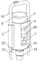
FIG. 1 is a schematic structural view of the present invention;
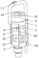
FIG. 2 is a schematic cross-sectional view of FIG. 1;
fig. 3 is a schematic structural diagram of the present invention.
In the figure: the device comprises a sleeve 1, a sleeve 2, a telescopic rod 21, a fastening knob 22, a servo motor 3, a motor seat 31, a fastening mechanism 4, a fixing seat 41, a clamping groove 42, a clamping column 43, a hexagon socket wrench 44, a plane bearing 5, a mounting seat 6, a shock absorber 61, a pressing plate 62, a sliding groove 7, an electric push rod 8, a protection box 9, a battery pack 91, a handle 10 and a switch group 11.
Detailed Description
The technical solutions in the embodiments of the present invention will be described clearly and completely with reference to the accompanying drawings in the embodiments of the present invention, and it is obvious that the described embodiments are only some embodiments of the present invention, not all embodiments. Based on the embodiments in the present invention, all other embodiments obtained by a person skilled in the art without creative work belong to the protection scope of the present invention.
Referring to fig. 1-3, the present invention provides a technical solution: the utility model provides a bolt fastening device, sleeve pipe 1 including the bottom opening setting, sleeve pipe 1's inside is slided and is provided with mount pad 6, sleeve pipe 1's side is equipped with spout 7, mount pad 6's side is equipped with the clamp plate 62 with spout 7 sliding connection, mount pad 6's bottom is equipped with bumper shock absorber 61, bumper shock absorber 61's bottom is equipped with motor cabinet 31, motor cabinet 31's bottom is equipped with servo motor 3, when servo motor 3 received reverse thrust, servo motor 3 passes through motor cabinet 31 extrusion bumper shock absorber 61, bumper shock absorber 61 takes place deformation and shortens, thereby protect equipment.
Be equipped with fastening device 4 on servo motor 3's the output shaft, fastening device 4 includes fixing base 41 with 3 fixed axle fixed connection of servo motor, the lower surface middle part of fixing base 41 is equipped with draw-in groove 42, and the inside activity joint of draw-in groove 42 has card post 43, the bottom of card post 43 is equipped with interior hexagonal spanner 44, move clamp plate 62 along spout 7, clamp plate 62 drives bumper shock absorber 61 through mount pad 6 and removes, bumper shock absorber 61 drives servo motor 3 through motor cabinet 31 and removes, servo motor 3 drives interior hexagonal spanner 44 through fixing base 41 and rotates simultaneously, thereby fasten the operation to the bolt, the manpower is saved, and the work efficiency is improved.
The upper surface of fixing base 41 is equipped with flat bearing 5, and flat bearing 5's upper surface and servo motor 3's bottom fixed connection improve servo motor 3 and fixing base 41's the effect of being connected.
The upper surface of mount pad 6 is equipped with the electric putter 8 that upwards stretches out and draws back, and the side upper end and the mount pad 6 fixed connection of electric putter 8 stiff end, and electric putter 8's input is connected with switch group 11's output electricity, and when fastening the bolt to horizontal position or upside, electric putter 8 can promote mount pad 6 and remove, and mount pad 6 can indirectly drive interior hexagonal spanner 44 and remove, facilitates the use.
The side of sleeve pipe 1 is equipped with sleeve 2, and the bottom of sleeve 2 is equipped with telescopic link 21, and the side lower extreme of telescopic link 21 stiff end is equipped with fastening knob 22, can adjust the length of telescopic link 21 to support whole equipment.
The top of sleeve 2 is equipped with handle 10, and the top of handle 10 is equipped with switch group 11, and sleeve pipe 1's top is equipped with protection box 9, and the inside of protection box 9 is equipped with group battery 91, and servo motor 3's input is connected with switch group 11's output electricity, and switch group 11's input is connected with group battery 91's output electricity.
The switch group 11 is provided with control buttons corresponding to the servo motor 3 and the electric push rod 8, and the servo motor 3 and the electric push rod 8 are common electrical components in the prior art.
Whole bolt-up device, can be according to the size quick replacement allen key 44 of bolt, and can fasten the bolt under multiple environment, need not many times to bow the operation and can fasten a plurality of bolts in proper order when fastening the lower and vertical ascending bolt in position, can use manpower sparingly, and when fastening the bolt of level fixing in lathe inside, need not to visit into lathe with workman's health inside, the security is high, and when fastening the bolt of the higher department in top, then need not to move the cat ladder and can operate, can improve work efficiency, and is easy to operate, high durability and convenient use.
When in use:
1. the length of the telescopic rod 21 is adjusted, and the fastening knob 22 is rotated to fix the telescopic rod 21, so that the height of the whole device is adjusted;
2. the inner hexagonal wrench 44 with a proper size can be selected according to the size of the bolt, and the clamping column 43 is clamped with the clamping groove 42;
3. when fastening a vertically downward bolt:
31. the handle 10 is held by hand to move the device, the inner hexagonal wrench 44 is clamped with the bolt, and the pressing plate 62 is stepped by feet;
32. the servo motor 3 is controlled to work through the switch group 11, the pressure plate 62 drives the shock absorber 61 to move through the mounting seat 6, the shock absorber 61 drives the servo motor 3 to move through the motor seat 31, the servo motor 3 drives the inner hexagonal wrench 44 to move through the fixing seat 41, and meanwhile, the servo motor 3 drives the inner hexagonal wrench 44 to rotate through the fixing seat 41, so that the bolt is fastened;
4. when fastening bolts in a horizontal manner or on top;
41. the device is well aligned with a bolt, an electric push rod 8 is controlled to work through a switch group 11, the electric push rod 8 drives a shock absorber 61 to move through a mounting seat 6, the shock absorber 61 drives a servo motor 3 to move through a motor seat 31, the servo motor 3 drives an inner hexagonal wrench 44 to move through a fixing seat 41, and the inner hexagonal wrench 44 is clamped with the bolt;
42. the servo motor 3 is controlled to work through the switch group 11, and the servo motor 3 drives the inner hexagonal wrench 44 to rotate through the fixing seat 41, so that the bolt is fastened.
The utility model discloses can be according to the size quick replacement allen key 44 of bolt, and can fasten the bolt under multiple environment, need not many times when fastening the lower and vertical ascending bolt in position and bow the operation and can fasten a plurality of bolts in proper order, can use manpower sparingly, and when fastening the bolt of fixing in lathe inside to the level, need not to visit into the lathe with workman's health inside, the security is high, and when fastening the bolt of the higher department in top, then need not to move the cat ladder and can operate, can improve work efficiency, and is easy to operate, and convenient to use.
The non-public part of the utility model is the prior art, and the concrete structure, the material and the working principle are not detailed. Although embodiments of the present invention have been shown and described, it will be appreciated by those skilled in the art that changes, modifications, substitutions and alterations can be made in these embodiments without departing from the principles and spirit of the invention, the scope of which is defined in the appended claims and their equivalents.
Claims (6)
1. A bolt fastening device comprises a sleeve (1) with an opening at the bottom, and is characterized in that: a mounting seat (6) is arranged inside the sleeve (1) in a sliding manner, a sliding groove (7) is formed in the side face of the sleeve (1), a pressing plate (62) connected with the sliding groove (7) in a sliding manner is arranged on the side face of the mounting seat (6), a shock absorber (61) is arranged at the bottom of the mounting seat (6), a motor seat (31) is arranged at the bottom of the shock absorber (61), a servo motor (3) is arranged at the bottom of the motor seat (31), and a fastening mechanism (4) is arranged on an output shaft of the servo motor (3);
the side of sleeve pipe (1) is equipped with sleeve (2), the top of sleeve pipe (2) is equipped with handle (10), the top of handle (10) is equipped with switch group (11), the top of sleeve pipe (1) is equipped with protection box (9), the inside of protection box (9) is equipped with group battery (91), and the input of servo motor (3) is connected with the output electricity of switch group (11), and the input of switch group (11) is connected with the output electricity of group battery (91).
2. The bolt-fastening device according to claim 1, wherein: the bottom of sleeve (2) is equipped with telescopic link (21), the side lower extreme of telescopic link (21) stiff end is equipped with fastening knob (22).
3. The bolt-fastening device according to claim 1, wherein: fastening device (4) include with servo motor (3) fixed axle fixed connection's fixing base (41), the lower surface middle part of fixing base (41) is equipped with draw-in groove (42), and the inside activity joint of draw-in groove (42) has card post (43), the bottom of card post (43) is equipped with interior hexagonal spanner (44).
4. The bolt-fastening device according to claim 3, wherein: the fixed seat (41) and the clamping column (43) are both magnetic.
5. The bolt-fastening device according to claim 3, wherein: the upper surface of fixing base (41) is equipped with flat bearing (5), the upper surface of flat bearing (5) and the bottom fixed connection of servo motor (3).
6. The bolt-fastening device according to claim 1, wherein: the upper surface of mount pad (6) is equipped with electric putter (8) that upwards stretch out and draw back, and the side upper end and the mount pad (6) fixed connection of electric putter (8) stiff end, and the input of electric putter (8) is connected with the output electricity of switch block (11).
Priority Applications (1)
| Application Number | Priority Date | Filing Date | Title |
|---|---|---|---|
| CN202021461240.9U CN212887425U (en) | 2020-07-22 | 2020-07-22 | Bolt fastening device |
Applications Claiming Priority (1)
| Application Number | Priority Date | Filing Date | Title |
|---|---|---|---|
| CN202021461240.9U CN212887425U (en) | 2020-07-22 | 2020-07-22 | Bolt fastening device |
Publications (1)
| Publication Number | Publication Date |
|---|---|
| CN212887425U true CN212887425U (en) | 2021-04-06 |
Family
ID=75291956
Family Applications (1)
| Application Number | Title | Priority Date | Filing Date |
|---|---|---|---|
| CN202021461240.9U Expired - Fee Related CN212887425U (en) | 2020-07-22 | 2020-07-22 | Bolt fastening device |
Country Status (1)
| Country | Link |
|---|---|
| CN (1) | CN212887425U (en) |
-
2020
- 2020-07-22 CN CN202021461240.9U patent/CN212887425U/en not_active Expired - Fee Related
Similar Documents
| Publication | Publication Date | Title |
|---|---|---|
| CN210442477U (en) | Auxiliary device for PCBA circuit board detection | |
| CN212887425U (en) | Bolt fastening device | |
| CN111069946A (en) | Novel special intelligent anchor clamps of numerical control machining center | |
| CN209970128U (en) | Planer fixture for spare and accessory part machining | |
| CN208209865U (en) | A kind of fixation device of photovoltaic module | |
| CN210295837U (en) | Enterprise image bulletin board | |
| CN213673920U (en) | Frame disassembling equipment for aluminum frame of solar photovoltaic panel | |
| CN208683471U (en) | A kind of electric pole pier head machine clamping device | |
| CN212807287U (en) | Environmental noise monitoring device | |
| CN206017341U (en) | A kind of convenient bolt that installs | |
| CN211046147U (en) | Low-voltage distribution cabinet convenient to installation | |
| CN210319912U (en) | Wisdom is modularization lamp pole for city | |
| CN210280757U (en) | Special counter boring tool for valve manufacturing | |
| CN219623205U (en) | Novel transfer case | |
| CN215033798U (en) | Nut side hole processing equipment | |
| CN220273614U (en) | Clamping device of new forms of energy photovoltaic cell board | |
| CN212484817U (en) | LED display screen module of quick installation | |
| CN220592938U (en) | Non-standard part taper hole positioning fixture | |
| CN213930004U (en) | Balancing device for installation of purifying equipment | |
| CN215035198U (en) | Mechanical transmission device of electric screwdriver | |
| CN210058333U (en) | Movable experiment table convenient to adjust | |
| CN215146959U (en) | Lathe drilling is supplementary to be used anchor clamps | |
| CN212683208U (en) | Improved self-centering tool clamp | |
| CN216879607U (en) | Chemical industry detects with novel grinder | |
| CN210677756U (en) | Linear guide convenient to installation is dismantled |
Legal Events
| Date | Code | Title | Description |
|---|---|---|---|
| GR01 | Patent grant | ||
| GR01 | Patent grant | ||
| CF01 | Termination of patent right due to non-payment of annual fee |
Granted publication date: 20210406 Termination date: 20210722 |
|
| CF01 | Termination of patent right due to non-payment of annual fee |