CN212878520U - Chair with leg supporting and adjusting device - Google Patents
Chair with leg supporting and adjusting device Download PDFInfo
- Publication number
- CN212878520U CN212878520U CN202021414709.3U CN202021414709U CN212878520U CN 212878520 U CN212878520 U CN 212878520U CN 202021414709 U CN202021414709 U CN 202021414709U CN 212878520 U CN212878520 U CN 212878520U
- Authority
- CN
- China
- Prior art keywords
- wall
- chair
- fixedly connected
- leg support
- adjusting device
- Prior art date
- Legal status (The legal status is an assumption and is not a legal conclusion. Google has not performed a legal analysis and makes no representation as to the accuracy of the status listed.)
- Active
Links
Images


Abstract
The utility model discloses a take shank to support adjusting device's chair, comprising a seat board, bottom one side fixedly connected with backup pad of bedplate, and one side intermediate position of backup pad is opened there is perpendicular groove, the top inner wall of erecting the groove rotates through the bearing and is connected with the pivot, and the bottom fixedly connected with threaded rod of pivot, and the bottom of threaded rod and the bottom inner wall of erecting the groove pass through the bearing and rotate and be connected, the opposite side top fixedly connected with just reverse motor of backup pad, and one side top of erecting the groove is opened there is the opening, is provided with the transmission assembly who passes the opening between the output shaft of just reverse motor and the outer wall of pivot. The utility model discloses adjust the position of movable sleeve on the threaded rod, adjust the gradient of shank backup pad for the chair has the function of supporting human leg, adjusts the length of whole shank backup pad, and the people of being convenient for use, and can avoid the problem of expansion plate roll-off in the slot under the condition that does not use.
Description
Technical Field
The utility model relates to the technical field of furniture, especially, relate to a take shank to support adjusting device's chair.
Background
The chair is a daily life furniture, a seat with a backrest and armrests, and is classified according to use: office chair, dining chair, bar chair, leisure chaise longue, deck chair, special chair, children's chair etc. the chair has very strong practicality, all can appear in each room, and its main function is exactly that the people of being convenient for have a rest, and modern chair pursues pleasing to the eye fashion, and some chairs are no longer alone the thing to sit on and endow more science and technology, make the mankind more convenient.
At present, when the existing household chair is used, most of the existing household chairs do not have a structure for supporting legs of a human body, when people rest on the chair, the legs cannot be effectively kept horizontal, and the chair can only be placed at a certain corner in a bending manner, so that the rest of the people is influenced, and therefore, the chair with the leg supporting and adjusting device is urgently needed to be designed to solve the problems.
Disclosure of Invention
The utility model aims at solving the defects existing in the prior art and providing a chair with a leg support adjusting device.
In order to achieve the above purpose, the utility model adopts the following technical scheme:
a chair with a leg supporting and adjusting device comprises a seat plate, wherein a supporting plate is fixedly connected to one side of the bottom of the seat plate, a vertical groove is formed in the middle position of one side of the supporting plate, a rotating shaft is rotatably connected to the inner wall of the top of the vertical groove through a bearing, a threaded rod is fixedly connected to the bottom of the rotating shaft, the bottom of the threaded rod is rotatably connected with the inner wall of the bottom of the vertical groove through a bearing, a forward and reverse rotating motor is fixedly connected to the top of the other side of the supporting plate, an opening is formed in the top of one side of the vertical groove, a transmission assembly penetrating through the opening is arranged between the output shaft of the forward and reverse rotating motor and the outer wall of the rotating shaft, a mounting groove is formed in one side of the seat plate, a leg supporting plate is rotatably connected between the inner walls of two sides of the, the inner walls of the two sides of the U-shaped frame are rotatably connected with a movable rod through a pin shaft.
Preferably, the transmission assembly comprises a transmission toothed belt and two gears, the two gears are respectively and fixedly connected to the outer wall of the rotating shaft and the outer wall of the output shaft of the forward and reverse rotating motor, and the inner wall of the transmission toothed belt is meshed with the outer wall of the gear.
Preferably, the inside of shank backup pad is opened there is the slot, and opens between the bottom of slot and the bottom of shank backup pad has the spacing groove, and the inside of spacing groove and the inside of slot are pegged graft and are had the expansion plate.
Preferably, one end of the top of the expansion plate is fixedly connected with a pedal.
Preferably, the expansion plate extends into a plurality of anti-slip strips fixedly connected to the tops of the two sides of the slot, and the outer walls of the anti-slip strips are in contact with the inner walls of the slot.
Preferably, the positive and negative rotation motor is connected with a switch through a wire, and the switch is connected with a power supply through a wire.
Preferably, the top of shank backup pad is opened has a plurality of recesses, and the inside of recess all pegs graft and have the sand grip, is provided with the spring between the bottom outer wall of sand grip and the bottom inner wall of recess, and the sand grip is the rubber material.
The utility model has the advantages that:
1. through the bedplate that sets up, the backup pad, erect the groove, positive reverse motor, drive assembly, the opening, the apparatus further comprises a rotating shaft, the threaded rod, the movable sleeve, the mounting groove, the shank backup pad, U type frame and movable rod, utilize positive reverse motor to drive assembly and rotate in the opening, drive pivot and threaded rod and rotate at erecting the inslot, adjust the position of movable sleeve on the threaded rod, adjust the height of movable rod, thereby adjust the gradient of shank backup pad, make the chair have the function of supporting to the human shank.
2. Through the shank backup pad, slot, spacing groove, expansion plate, running-board and the antislip strip that sets up, the length of whole shank backup pad is adjusted to the position of adjustable expansion plate in the slot, and the people of being convenient for use to the effect of accessible antislip strip, on the one hand carry on spacingly to the position of expansion plate, on the other hand can increase the frictional force of expansion plate and slot, avoids the problem of expansion plate from the interior roll-off of slot under the condition of not using.
3. Through shank backup pad, recess, spring and the sand grip that sets up, when human shank moves in the shank backup pad, the effect of accessible spring and sand grip carries out certain massage to the shank and handles, improves the result of use.
Drawings
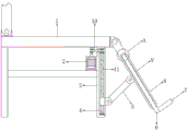
Fig. 1 is a front sectional view of a chair with a leg support adjustment device according to embodiment 1;
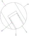
FIG. 2 is a schematic view of the structure of a movable rod and a movable sleeve of a chair with a leg support adjustment device according to embodiment 1;
FIG. 3 is an enlarged schematic view of the structure at A in FIG. 1 according to example 1;
FIG. 4 is a schematic view showing the structure of a leg support plate and a mounting groove of a chair with a leg support adjusting device according to embodiment 1;
fig. 5 is a schematic view of the structure of the rib and the spring of the chair with the leg support adjusting device according to embodiment 2.
In the figure: the device comprises a seat plate 1, a forward and reverse rotation motor 2, a support plate 3, a vertical groove 4, a movable rod 5, a telescopic plate 6, a pedal 7, a leg support plate 8, a slot 9, a transmission assembly 10, a threaded rod 11, a U-shaped frame 12, a movable sleeve 13, an anti-slip strip 14, a mounting groove 15, a convex strip 16 and a spring 17.
Detailed Description
The technical solution of the present patent will be described in further detail with reference to the following embodiments.
Reference will now be made in detail to embodiments of the present patent, examples of which are illustrated in the accompanying drawings, wherein like or similar reference numerals refer to the same or similar elements or elements having the same or similar function throughout. The embodiments described below with reference to the drawings are exemplary only for the purpose of explaining the present patent and are not to be construed as limiting the present patent.
In the description of this patent, it is to be understood that the terms "center," "upper," "lower," "front," "rear," "left," "right," "vertical," "horizontal," "top," "bottom," "inner," "outer," and the like are used in the orientations and positional relationships indicated in the drawings for the convenience of describing the patent and for the simplicity of description, and are not intended to indicate or imply that the referenced devices or elements must have a particular orientation, be constructed and operated in a particular orientation, and are not to be considered limiting of the patent.
In the description of this patent, it is noted that unless otherwise specifically stated or limited, the terms "mounted," "connected," and "disposed" are to be construed broadly and can include, for example, fixedly connected, disposed, detachably connected, disposed, or integrally connected and disposed. The specific meaning of the above terms in this patent may be understood by those of ordinary skill in the art as appropriate.
Example 1
Referring to fig. 1-4, a chair with a leg supporting and adjusting device comprises a seat plate 1, wherein a support plate 3 is welded on one side of the bottom of the seat plate 1, a vertical groove 4 is formed in the middle position of one side of the support plate 3, the inner wall of the top of the vertical groove 4 is rotatably connected with a rotating shaft through a bearing, the bottom of the rotating shaft is connected with a threaded rod 11 through a bolt, the bottom of the threaded rod 11 is rotatably connected with the inner wall of the bottom of the vertical groove 4 through a bearing, the top of the other side of the support plate 3 is connected with a forward and reverse motor 2 through a bolt, an opening is formed in the top of one side of the vertical groove 4, a transmission assembly 10 penetrating through the opening is arranged between the output shaft of the forward and reverse motor 2 and the outer wall of the rotating shaft, a mounting groove 15 is formed in one side of the seat plate 1, a leg support plate 8 is rotatably connected between the inner walls of the two sides, the inner walls of the two sides of the U-shaped frame 12 are rotatably connected with a movable rod 5 through a pin shaft.
Wherein, drive assembly 10 includes drive cog belt and two gears, and two gears pass through bolted connection respectively and just reverse motor 2's output shaft outer wall in the outer wall of pivot, and the inner wall of drive cog belt meshes with the outer wall of gear mutually.
Wherein, the inside of shank backup pad 8 is opened there is slot 9, and opens between the bottom of slot 9 and the bottom of shank backup pad 8 has the spacing groove, and the inside of spacing groove and the inside of slot 9 are pegged graft and are had expansion plate 6.
Wherein, a pedal 7 is welded at one end of the top of the expansion plate 6.
Wherein, a plurality of antislip strips 14 are welded on the top of the two sides of the slot 9 into which the expansion plate 6 extends, and the outer walls of the antislip strips 14 contact with the inner wall of the slot 9.
Wherein, the positive and negative rotation motor 2 is connected with a switch through a wire, and the switch is connected with a power supply through a wire.
The working principle is as follows: during the use, the user utilizes just reversing motor 2 to drive transmission assembly 10 and rotates in the opening, drive pivot and threaded rod 11 and rotate in erecting groove 4, adjust the position of movable sleeve 13 on threaded rod 11, adjust the height of movable rod 5, thereby adjust the gradient of shank backup pad 8, make the chair have the function of supporting the human leg, the position of the adjustable expansion plate 6 of user in slot 9, adjust the length of whole shank backup pad 8, be convenient for people to use, and the effect of accessible antislip strip 14, the position to expansion plate 6 is spacing on the one hand, on the other hand can increase the frictional force of expansion plate 6 and slot 9, avoid expansion plate 6 from the problem of roll-off in the slot 9 under the condition of not using.
Example 2
Referring to fig. 5, in this embodiment, compared with embodiment 1, a plurality of grooves are formed at the top of the leg support plate 8, protruding strips 16 are inserted into the grooves, a spring 17 is disposed between the outer wall of the bottom of the protruding strip 16 and the inner wall of the bottom of the groove, and the protruding strips 16 are made of rubber.
The working principle is as follows: when the legs of the human body act on the leg supporting plate 8, the legs can be massaged to a certain extent through the action of the springs 17 and the convex strips 16, and the using effect is improved.
The above, only be the concrete implementation of the preferred embodiment of the present invention, but the protection scope of the present invention is not limited thereto, and any person skilled in the art is in the technical scope of the present invention, according to the technical solution of the present invention and the utility model, the concept of which is equivalent to replace or change, should be covered within the protection scope of the present invention.
Claims (7)
1. A chair with a leg support adjusting device comprises a seat plate (1) and is characterized in that a supporting plate (3) is fixedly connected to one side of the bottom of the seat plate (1), a vertical groove (4) is formed in the middle of one side of the supporting plate (3), a rotating shaft is rotatably connected to the inner wall of the top of the vertical groove (4) through a bearing, a threaded rod (11) is fixedly connected to the bottom of the rotating shaft, the bottom of the threaded rod (11) is rotatably connected to the inner wall of the bottom of the vertical groove (4) through a bearing, a forward and reverse motor (2) is fixedly connected to the top of the other side of the supporting plate (3), an opening is formed in the top of one side of the vertical groove (4), a transmission assembly (10) penetrating through the opening is arranged between the output shaft of the forward and reverse motor (2) and the outer wall of the rotating shaft, a mounting groove (15) is formed in one side of the seat plate (, the outer wall threaded connection of threaded rod (11) has movable sleeve (13), and the equal fixedly connected with U type frame (12) in one side of movable sleeve (13) and one side of shank backup pad (8), rotates through the round pin axle between the both sides inner wall of U type frame (12) and is connected with movable rod (5).
2. The chair with the leg supporting and adjusting device as claimed in claim 1, wherein the transmission assembly (10) comprises a transmission toothed belt and two gears, the two gears are fixedly connected to the outer wall of the rotating shaft and the outer wall of the output shaft of the forward and reverse rotating motor (2), respectively, and the inner wall of the transmission toothed belt is meshed with the outer wall of the gears.
3. A chair with leg support adjusting device according to claim 2, characterized in that the leg support plate (8) is provided with a slot (9) inside, a limit groove is provided between the bottom of the slot (9) and the bottom of the leg support plate (8), and the inside of the limit groove and the inside of the slot (9) are inserted with the expansion plate (6).
4. A chair with leg support adjustment device according to claim 3, characterized in that the top end of the extension plate (6) is fixedly connected with a foot pedal (7).
5. The chair with the leg support adjusting device as claimed in claim 4, wherein a plurality of anti-slip strips (14) are fixedly connected to the top of both sides of the extension plate (6) extending into the slot (9), and the outer walls of the anti-slip strips (14) are in contact with the inner walls of the slot (9).
6. A chair with leg support adjusting device according to any of claims 1-5, characterized in that the forward and reverse rotation motor (2) is connected with a switch through a wire, and the switch is connected with a power supply through a wire.
7. The chair with the leg support adjusting device as claimed in claim 1, wherein the top of the leg support plate (8) is provided with a plurality of grooves, and the grooves are inserted with a convex strip (16), a spring (17) is arranged between the outer wall of the bottom of the convex strip (16) and the inner wall of the bottom of the groove, and the convex strip (16) is made of rubber.
Priority Applications (1)
| Application Number | Priority Date | Filing Date | Title |
|---|---|---|---|
| CN202021414709.3U CN212878520U (en) | 2020-07-17 | 2020-07-17 | Chair with leg supporting and adjusting device |
Applications Claiming Priority (1)
| Application Number | Priority Date | Filing Date | Title |
|---|---|---|---|
| CN202021414709.3U CN212878520U (en) | 2020-07-17 | 2020-07-17 | Chair with leg supporting and adjusting device |
Publications (1)
| Publication Number | Publication Date |
|---|---|
| CN212878520U true CN212878520U (en) | 2021-04-06 |
Family
ID=75288611
Family Applications (1)
| Application Number | Title | Priority Date | Filing Date |
|---|---|---|---|
| CN202021414709.3U Active CN212878520U (en) | 2020-07-17 | 2020-07-17 | Chair with leg supporting and adjusting device |
Country Status (1)
| Country | Link |
|---|---|
| CN (1) | CN212878520U (en) |
-
2020
- 2020-07-17 CN CN202021414709.3U patent/CN212878520U/en active Active
Similar Documents
| Publication | Publication Date | Title |
|---|---|---|
| EP3777807A1 (en) | Multifunctional wheelchair | |
| CN212878520U (en) | Chair with leg supporting and adjusting device | |
| CN213524531U (en) | Conference seat suitable for conference service | |
| CN112674527B (en) | Adjustable intelligent massage sofa | |
| CN212878525U (en) | Armrest of leisure chair | |
| CN210540011U (en) | Linkage mechanism of sitting and lying device | |
| CN113017326A (en) | Massage chair | |
| CN210540096U (en) | Novel chair armrest | |
| CN216220823U (en) | Multifunctional office chair | |
| CN219680169U (en) | Sofa metal framework and reclining type couch | |
| CN215875427U (en) | Body type self-adaptation massage armchair | |
| CN115413907B (en) | Zero gravity sofa | |
| CN215229830U (en) | Massage armchair and support frame thereof | |
| CN216358416U (en) | Multifunctional beach chair | |
| CN212878553U (en) | Intelligent sofa with massage function | |
| CN212938947U (en) | Connecting mechanism for leisure chair | |
| CN216627955U (en) | Four-back waist-supporting learning chair | |
| CN219845743U (en) | Office chair with adjustable seat board and backrest | |
| CN217429615U (en) | Furniture bed with adjustable bed backrest angle | |
| CN210493385U (en) | Comfortable garden seat | |
| CN215229833U (en) | Massage chair and support frame thereof | |
| CN217610179U (en) | Chair with waist massage function | |
| CN217488090U (en) | Chair with adjustable chair back height | |
| CN218246416U (en) | Novel iron chair frame | |
| CN219762887U (en) | Apartment chair with waist support effect |
Legal Events
| Date | Code | Title | Description |
|---|---|---|---|
| GR01 | Patent grant | ||
| GR01 | Patent grant |