CN212843635U - Induction type electric power instrument - Google Patents
Induction type electric power instrument Download PDFInfo
- Publication number
- CN212843635U CN212843635U CN202022000403.XU CN202022000403U CN212843635U CN 212843635 U CN212843635 U CN 212843635U CN 202022000403 U CN202022000403 U CN 202022000403U CN 212843635 U CN212843635 U CN 212843635U
- Authority
- CN
- China
- Prior art keywords
- infrared sensor
- main control
- shell
- control board
- electrically connected
- Prior art date
- Legal status (The legal status is an assumption and is not a legal conclusion. Google has not performed a legal analysis and makes no representation as to the accuracy of the status listed.)
- Active
Links
Images


Abstract
The utility model discloses an induction type electric power instrument, which comprises a shell and a main control board; the shell comprises a top plate and side doors, and slots for horizontally inserting the main control board are arranged on two sides of the inner surface of the top plate; a limiting plate is arranged on one side, close to the side door, of the inner cavity of the shell, one side face of the limiting plate is abutted to one end of the main control plate, the other side face of the limiting plate is rotatably connected with a screw rod, and the screw rod penetrates through the side door and is in threaded connection with the shell; the limiting plate is provided with a first infrared sensor and a second infrared sensor, the shell is provided with an induction hole, the position of the induction hole corresponds to that of the first infrared sensor, and the first infrared sensor is electrically connected to the main control board; the main control panel is electrically connected with the liquid crystal display screen; and the second infrared sensor is electrically connected with the LED lamp bank. The utility model discloses can respond to being close of operation personnel to light liquid crystal display backlight and/or the interior LED banks of instrument case, economize on electricity more, and reduce the heat dissipation, slow down the internal circuit board ageing, combine the circuit board of reassembling type structure, be more convenient for look up the table and maintain the operation.
Description
Technical Field
The utility model relates to an electric power instrument technical field, more specifically the utility model relates to an induction type electric power instrument that says so.
Background
At present, electric power instruments are widely used for various control systems, the traditional pointer dial display of the electric power instruments is upgraded to liquid crystal display digital display, and a liquid crystal display screen enables a user to more intuitively obtain electric power parameters.
However, in the electric power control system, in order to facilitate the collection of electric power parameters, current electric power instrument liquid crystal display often adopts the mode that is always bright in a poor light, no matter whether have personnel to operate the action, its display screen is in the state of always being bright, this not only causes the electric energy waste, but also can lead to the instrument to generate heat, if outside the electric power instrument of row that can not be timely, can cause the phenomenon of circuit ageing and electric leakage, and, because the electric power instrument often installs the different positions at electric power system, also very inconvenient to the maintenance of instrument, the influence of light makes can't carry out troubleshooting and maintenance operation at the instrument mounted position. If the liquid crystal display screen of the electric power meter is changed into a long-time off mode in order to reduce heat dissipation, a user needs to check the meter by pressing up and down keys to brighten the backlight and then check the meter, so that the operation is very inconvenient, great workload is brought to the user, and in addition, risks are brought to the personal safety of the user.
Therefore, it is an urgent need to solve the problem of the art to provide an inductive power meter with an inductive function, which can slow down the aging of the internal circuit board and is convenient for maintenance.
Disclosure of Invention
In view of this, the utility model provides an induction type electric power instrument can respond to being close of operation personnel to light liquid crystal display backlight and/or the interior LED banks of instrument case, combine the circuit board of reassembling type structure, be more convenient for look up the table and maintain the operation.
In order to achieve the above purpose, the utility model adopts the following technical scheme:
an induction type electric power instrument comprises a shell and a main control board positioned inside the shell;
the shell comprises a top plate and side doors, and slots for horizontally inserting the main control panel are formed in two sides of the inner surface of the top plate; a limiting plate is arranged on one side, close to the side door, of the inner cavity of the shell, one side face of the limiting plate is abutted to one end of the main control plate, the other side face of the limiting plate is rotatably connected with a screw rod, and the tail end of the screw rod penetrates through the side door and is in threaded connection with the shell; one side face, facing the inner cavity of the shell, of the limiting plate is provided with a first infrared sensor and a second infrared sensor, the shell is provided with an induction hole, the position of the induction hole corresponds to that of the first infrared sensor, and the first infrared sensor is electrically connected to the main control board;
the main control board is electrically connected with the liquid crystal display screen and is used for receiving a control signal sent by the main control board according to the sensing signal of the infrared sensor; and the main control board is provided with an LED lamp bank, and the LED lamp bank is electrically connected with the second infrared sensor.
The technical effect of the technical scheme is as follows: can perception staff's being close to through infrared sensor one to control liquid crystal display and light, realize the operation of checking meter, can perceive the action that the staff opened the side door through infrared sensor two, and control the interior LED banks of table and light, realize the maintenance operation. Simultaneously because infrared sensor one and infrared sensor two are located the limiting plate, and the limiting plate and side door interlock, consequently, do not influence each other when checking meter and maintenance work to the control process of liquid crystal display and LED banks, further save the electric energy. The main control board is fixed in a top inserting mode, and the whole circuit board is convenient to disassemble, assemble and maintain.
Preferably, the slot is located the front side and the back side of roof internal surface, and the slot bottom is equipped with the protruding edge towards the casing inner chamber, can increase the bearing of slot to main control board and relevant function circuit board.
Preferably, the screw is rotationally connected with the limiting plate through a bearing; the tail end of the screw rod is connected with a rotating handle, and the outer diameter of the rotating handle is larger than the inner diameter of a threaded hole in the shell, and the threaded hole is used for penetrating out of the screw rod.
Preferably, the second infrared sensor is positioned on the back of the first infrared sensor, and the first infrared sensor completely shields the second infrared sensor; the probe of the infrared sensor II faces the inner cavity of the shell, and the probe of the infrared sensor I faces the induction hole and is used for inducing an external environment. The infrared sensor II can not be influenced by infrared light rays penetrating through the sensing hole, only when the side door is opened by an operator, infrared signals are detected, the LED lamp bank in the inner cavity of the shell is subjected to sensing control, the infrared sensor II and the infrared sensor work independently respectively, the infrared sensor II and the infrared sensor do not interfere with each other, and the independent control process of the LED lamp bank and the liquid crystal display screen light is guaranteed.
Preferably, the main control board is electrically connected with a sampling board, a power supply board and a screen board, a group of LED lamp sets are arranged on the sampling board, the power supply board and the screen board, and the LED lamp sets are electrically connected with the second infrared sensor. Each group of LED lamp group illuminates each circuit board respectively, so that maintenance personnel can conveniently overhaul components on the circuit boards.
Preferably, still include, locate fan in the casing, the fan install with on the inner wall of the casing curb plate that the side door is relative, and with main control board electric connection, be equipped with heat dissipation grille on the side door. The fan and the grille are relatively convenient for air flow circulation, and heat dissipation capacity is increased. Sampling board, power strip and otter board all forward cartridge on the main control board, forward be with slot parallel direction, fan air current passes between each function circuit board on the main control board, increases inter-plate heat dissipation.
Preferably, the housing includes a display panel, and the liquid crystal display and the sensing hole are both located on the display panel.
Preferably, a thermosensitive sensor is further arranged in the shell and electrically connected with the main control board for monitoring the temperature value in the shell in real time.
Known through foretell technical scheme, compare with prior art, the beneficial effect of the utility model includes: can perception staff's being close to through infrared sensor one to control liquid crystal display and light, realize the operation of checking meter, can perceive the action that the staff opened the side door through infrared sensor two, and control the interior LED banks of table and light, realize the maintenance operation. Simultaneously because infrared sensor one and infrared sensor two are located the limiting plate, and the limiting plate and side door interlock, consequently, do not influence each other when checking meter and maintenance work to the control process of liquid crystal display and LED banks, further save the electric energy. The main control board is fixed in a top inserting mode, so that the whole circuit board can be conveniently dismounted and maintained, and the mounting position of the fan is more convenient for heat dissipation inside the shell.
Drawings
In order to more clearly illustrate the embodiments of the present invention or the technical solutions in the prior art, the drawings required to be used in the description of the embodiments or the prior art will be briefly described below, it is obvious that the drawings in the following description are only embodiments of the present invention, and for those skilled in the art, other drawings can be obtained according to the provided drawings without creative efforts.
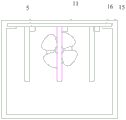
Fig. 1 is a front view of an internal structure of an induction type power meter provided by the present invention;
fig. 2 is a side view of the internal structure of the induction type power meter provided by the present invention;
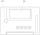
fig. 3 is a front view of an external structure of the induction type power meter provided by the present invention;
fig. 4 is a side view of the external structure of the induction type power meter provided by the present invention;
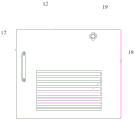
fig. 5 is the utility model provides an induction type electric power instrument control panel installation schematic diagram.
Detailed Description
The technical solutions in the embodiments of the present invention will be described clearly and completely with reference to the accompanying drawings in the embodiments of the present invention, and it is obvious that the described embodiments are only some embodiments of the present invention, not all embodiments. Based on the embodiments in the present invention, all other embodiments obtained by a person skilled in the art without creative work belong to the protection scope of the present invention.
Referring to fig. 1-2, the present embodiment provides an inductive power meter, which includes a housing 1 and a main control board 2 located inside the housing 1; the shell 1 comprises a top plate 11 and a side door 12, wherein slots 15 for horizontally inserting the main control board 2 are formed in two sides of the inner surface of the top plate 11; a limit plate 13 is arranged on one side of the inner cavity of the shell 1 close to the side door 12, one side surface of the limit plate 13 is abutted against one end of the main control plate 2, the other side surface is rotatably connected with a screw rod 20, and the tail end of the screw rod 20 penetrates through the side door 12 and is in threaded connection with the shell 1; one side surface of the limiting plate 13 facing the inner cavity of the shell 1 is provided with a first infrared sensor 3 and a second infrared sensor; an LED lamp group 5 is installed on the main control board 2, and the LED lamp group 5 is electrically connected with the second infrared sensor. The second infrared sensor is positioned on the back of the first infrared sensor 3, and the first infrared sensor 3 completely shields the second infrared sensor; the probe of the second infrared sensor faces the inner cavity of the shell 1, and the probe of the first infrared sensor 3 faces the sensing hole 14 and is used for sensing the external environment.
The operation process of maintenance personnel is as follows: when the maintenance personnel open the side door 12 through the handle 17, the side door 12 moves together with the screw rod 20 and the limiting plate 13, at this moment, the infrared sensor II positioned at the back of the infrared sensor I3 senses a human body, and the LED lamp group 5 on the main control panel 2 is controlled to be lightened. The opening angle of the side door 12 is adjustable, if the LED lamp bank 5 needs to be lightened, the liquid crystal display screen 21 is lightened in a backlight mode, the side door 12 only needs to be opened by 180 degrees, and the probe of the infrared sensor 3 can sense maintenance personnel located at the position of the side door 12.
Referring to fig. 3, the shell 1 is provided with an induction hole 14, the position of the induction hole 14 corresponds to the position of the first infrared sensor 3, and the first infrared sensor 3 is electrically connected to the main control board 2; the main control board 2 is electrically connected with the liquid crystal display screen 21 and is used for receiving a control signal sent by the main control board 2 according to the sensing signal of the first infrared sensor 3.
The operation process of meter reading personnel is as follows: when a meter reading person approaches the electric power meter, the first infrared sensor 3 senses a human body through the sensing hole 14 and sends an infrared sensing signal to the main control board 2, and the main control board 2 generates a control signal according to the infrared sensing signal and controls the liquid crystal display screen 21 to be lit in a backlight mode.
In order to further optimize the above technical solution, the slots 15 are located at the front side and the rear side of the inner surface of the top plate 11, and the bottom of the slots 15 is provided with a convex edge 16 facing the inner cavity of the housing 1.
Referring to fig. 4, in order to further optimize the above technical solution, the screw rod 20 is rotatably connected with the limiting plate 13 through a bearing, and the rotary connection can be realized by adopting a bearing manner; the tail end of the screw rod 20 is connected with a rotating handle 19, and the outer diameter of the rotating handle 19 is larger than the inner diameter of a threaded hole in the shell 1, through which the screw rod 20 penetrates.
The limiting plate 13 compresses tightly the limiting process to the main control board 2 and does: the handle 19 is rotated by hand, the screw 20 rotates towards the shell 1 along the threaded hole, and the limiting plate 13 is rotatably connected with the screw 20, so that the limiting plate 13 cannot rotate along with the screw 20 and only abuts against one end of the main control plate 2 along the advancing direction of the screw 20.
Referring to fig. 5, in order to further optimize the above technical solution, the main control board 2 is electrically connected with a sampling board 23, a power board 24 and a screen board 25, the sampling board 23, the power board 24 and the screen board 25 are all provided with a group of LED lamp sets 5, and the LED lamp sets 5 are electrically connected with the second infrared sensor. The sampling board 23 processes the power sampling signal, and the processed signal is transmitted to an external device through the network board 25 according to the ethernet transmission standard.
In order to further optimize the above technical solution, the heat dissipation device further includes a fan 22 disposed in the casing 1, wherein the fan 22 is mounted on an inner wall of a side plate of the casing 1 opposite to the side door 12 and electrically connected to the main control board 2, and a heat dissipation grille 18 is disposed on the side door 12.
In order to further optimize the above technical solution, the housing 1 includes a display panel, and the liquid crystal display 21 and the sensing hole 14 are both located on the display panel.
In order to further optimize the technical scheme, a heat-sensitive sensor is further arranged in the shell 1 and is electrically connected with the main control board 2.
The embodiments in the present description are described in a progressive manner, each embodiment focuses on differences from other embodiments, and the same and similar parts among the embodiments are referred to each other. The device disclosed by the embodiment corresponds to the method disclosed by the embodiment, so that the description is simple, and the relevant points can be referred to the method part for description.
The previous description of the disclosed embodiments is provided to enable any person skilled in the art to make or use the present invention. Various modifications to these embodiments will be readily apparent to those skilled in the art, and the generic principles defined herein may be applied to other embodiments without departing from the spirit or scope of the invention. Thus, the present invention is not intended to be limited to the embodiments shown herein but is to be accorded the widest scope consistent with the principles and novel features disclosed herein.
Claims (8)
1. An induction type electric power instrument is characterized by comprising a shell and a main control board positioned in the shell;
the shell comprises a top plate and side doors, and slots for horizontally inserting the main control panel are formed in two sides of the inner surface of the top plate; a limiting plate is arranged on one side, close to the side door, of the inner cavity of the shell, one side face of the limiting plate is abutted to one end of the main control plate, the other side face of the limiting plate is rotatably connected with a screw rod, and the tail end of the screw rod penetrates through the side door and is in threaded connection with the shell; one side face, facing the inner cavity of the shell, of the limiting plate is provided with a first infrared sensor and a second infrared sensor, the shell is provided with an induction hole, the position of the induction hole corresponds to that of the first infrared sensor, and the first infrared sensor is electrically connected to the main control board;
the main control board is electrically connected with the liquid crystal display screen and is used for receiving a control signal sent by the main control board according to the sensing signal of the infrared sensor; and the main control board is provided with an LED lamp bank, and the LED lamp bank is electrically connected with the second infrared sensor.
2. An inductive power meter according to claim 1, wherein the slots are located on the front and rear sides of the inner surface of the top plate, and the bottom of the slots is provided with a ledge facing the cavity of the housing.
3. The inductive power meter according to claim 1, wherein the screw is rotatably connected to the limit plate by a bearing; the tail end of the screw rod is connected with a rotating handle, and the outer diameter of the rotating handle is larger than the inner diameter of a threaded hole in the shell, and the threaded hole is used for penetrating out of the screw rod.
4. The inductive power meter according to claim 1, wherein said second infrared sensor is located on the back of said first infrared sensor, and said first infrared sensor completely shields said second infrared sensor; the probe of the infrared sensor II faces the inner cavity of the shell, and the probe of the infrared sensor I faces the induction hole and is used for inducing an external environment.
5. The induction type electric power instrument as claimed in claim 1, wherein the main control board is electrically connected with a sampling board, a power board and a screen board, a group of LED lamp sets are arranged on the sampling board, the power board and the screen board, and the LED lamp sets are electrically connected with the second infrared sensor.
6. The inductive power meter according to claim 1, further comprising a fan disposed in the housing, wherein the fan is mounted on an inner wall of the housing side plate opposite to the side door and electrically connected to the main control board, and a heat dissipation grid is disposed on the side door.
7. An inductive power meter according to claim 1, wherein said housing includes a display panel, said liquid crystal display and said sensing aperture being located on said display panel.
8. The inductive power meter of claim 1 further comprising a heat sensitive sensor disposed within said housing, said heat sensitive sensor being electrically connected to said main control panel.
Priority Applications (1)
| Application Number | Priority Date | Filing Date | Title |
|---|---|---|---|
| CN202022000403.XU CN212843635U (en) | 2020-09-14 | 2020-09-14 | Induction type electric power instrument |
Applications Claiming Priority (1)
| Application Number | Priority Date | Filing Date | Title |
|---|---|---|---|
| CN202022000403.XU CN212843635U (en) | 2020-09-14 | 2020-09-14 | Induction type electric power instrument |
Publications (1)
| Publication Number | Publication Date |
|---|---|
| CN212843635U true CN212843635U (en) | 2021-03-30 |
Family
ID=75147201
Family Applications (1)
| Application Number | Title | Priority Date | Filing Date |
|---|---|---|---|
| CN202022000403.XU Active CN212843635U (en) | 2020-09-14 | 2020-09-14 | Induction type electric power instrument |
Country Status (1)
| Country | Link |
|---|---|
| CN (1) | CN212843635U (en) |
-
2020
- 2020-09-14 CN CN202022000403.XU patent/CN212843635U/en active Active
Similar Documents
| Publication | Publication Date | Title |
|---|---|---|
| CN212843635U (en) | Induction type electric power instrument | |
| CN211718235U (en) | Monitoring equipment for environmental supervision | |
| CN214959486U (en) | Energy-saving infrared induction type switch | |
| CN215375624U (en) | Multifunctional electric power monitoring instrument | |
| CN215931979U (en) | Outdoor ammeter box | |
| CN208521452U (en) | A kind of intelligent infrared controller of anti-stop signal barrier | |
| CN219532833U (en) | Multi-functional air matter element monitoring facilities | |
| CN112504449A (en) | Multispectral sensor convenient to maintenance | |
| CN209945635U (en) | Electronic gas leakage concentration detection device | |
| CN206251497U (en) | A kind of new type inverter rack | |
| CN211374454U (en) | Portable environment detector | |
| CN211603297U (en) | Electric energy meter with night visual mechanism | |
| CN220823601U (en) | Intelligent electric power instrument with heat dissipation function | |
| CN214896867U (en) | Intelligent power supply control device for mineral resource exploration | |
| CN219716391U (en) | Liquid crystal display with high temperature early warning function | |
| CN220210881U (en) | Concentration remote alarm control box | |
| CN219124525U (en) | Electric energy quality terminal precision evaluation device | |
| CN215986429U (en) | Safety monitoring and early warning device for distribution box | |
| CN214757374U (en) | Intelligent weak current control box for building with dustproof construction | |
| CN211373829U (en) | Tunnel lamp intensity detection device for building engineering | |
| CN213024107U (en) | Environment intelligent temperature and humidity controller | |
| CN215935026U (en) | Communication conversion module based on wireless router | |
| CN212587930U (en) | Distribution box with built-in lighting structure | |
| CN219301677U (en) | Single-board integrated voice temperature and humidity measuring instrument | |
| CN213517312U (en) | Guide rail electric energy meter with remote upgrading function |
Legal Events
| Date | Code | Title | Description |
|---|---|---|---|
| GR01 | Patent grant | ||
| GR01 | Patent grant |