Detachable connecting device for building steel structure
Technical Field
The utility model relates to a technical field is connected to the steel construction, especially relates to a building steel construction can dismantle connecting device.
Background
Compared with the traditional concrete building, the steel plate or the section steel replaces reinforced concrete, so that the steel structure building has higher strength and better shock resistance. And because the components can be manufactured in factories and installed on site, the construction period is greatly reduced. Because the steel can be repeatedly used, the construction waste can be greatly reduced, and the steel is more environment-friendly, so the steel is widely adopted by all countries in the world and is applied to industrial buildings and civil buildings.
Through retrieval, the Chinese patent with publication number CN209243938U discloses a connecting device of a building steel structure, which comprises a first steel structure, a second steel structure and a connecting plate; the first steel structure and the second steel structure are connected through a connecting plate; a first limiting groove and a second limiting groove are formed in the side face, in contact with the first steel structure and the second steel structure, of the connecting plate; the first steel structure is limited by the first limiting groove, and the second steel structure is limited by the second limiting groove; still including protective sleeve and elastic buffer piece, the protective sleeve cladding is provided with first steel construction, second steel construction and connecting plate, elastic buffer piece roof pressure sets up between the close end of first steel construction and second steel construction. The above patents suffer from the following disadvantages: because the steel construction all is just what tailor according to fixed dimension when designing, when carrying out the construction installation, can be because certain installation error appears in the straightness that hangs down of installation or buried degree of depth etc. and above-mentioned patent utilizes a plurality of spacing grooves to come the steel construction to fix a position and share load, but in case the construction error appears, its dimensional adjustment that can't carry out the steel construction junction according to actual conditions directly leads to the fixed steel construction in front end to need fix a position again, leads to the influence of very big degree to the construction progress.
SUMMERY OF THE UTILITY MODEL
The utility model aims at solving the defects existing in the prior art and providing a detachable connecting device of a building steel structure.
In order to achieve the above purpose, the utility model adopts the following technical scheme:
a detachable connecting device for a building steel structure comprises a longitudinal steel member, two transverse steel members, a main member connecting member for connecting the longitudinal steel member and the transverse steel members, a first side member connecting member and a second side member connecting member, the inner wall of the main structure connecting piece is provided with a first waist-shaped hole, the inner wall of the main structure connecting piece wraps the outer wall of the longitudinal steel member and is fixedly connected with the longitudinal steel member through a longitudinal steel structure connecting bolt, the inner walls of the first side structure connecting piece and the second side structure connecting piece are both provided with a second waist-shaped hole, the two transverse steel members are respectively and fixedly connected with the two second waist-shaped holes through transverse steel structure connecting bolts, the second side member connecting piece is welded and fixed with the main member connecting piece, the first side member connecting piece is connected with the main member connecting piece in a sliding way, and the sliding connection part is provided with a limiting component, and the outer wall of the top part of the main structure connecting piece is provided with an adjusting component.
As a further aspect of the present invention: the adjusting assembly comprises an adjusting ring and an adjusting bolt, four first reinforcing ribs are welded on the outer wall of the top of the main structure connecting piece, the outer wall of the adjusting ring is welded on the outer walls of the two symmetrical first reinforcing ribs, and the outer wall of the adjusting bolt is connected on the inner wall of the adjusting ring through threads.
As a further aspect of the present invention: the bottom outer wall of the adjusting bolt is in contact with the top outer wall of the longitudinal steel member.
As a further aspect of the present invention: the limiting assembly comprises a first limiting bolt and a second limiting bolt, a first sliding groove and a second sliding groove are respectively formed in the inner wall of the main structure connecting piece, a first lug and a second lug are integrally formed on the outer wall of the first side structure connecting piece, the first lug is connected with the first sliding groove in a sliding mode, the second lug is connected with the second sliding groove in a sliding mode, the outer wall of the first limiting bolt is connected to the inner wall, close to the second sliding groove, of the main structure connecting piece through threads, and the outer wall of the second limiting bolt is connected to the inner wall, close to the first sliding groove, of the main structure connecting piece through threads.
As a further aspect of the present invention: the first sliding groove, the first convex block, the second convex block and the second sliding groove are all in T-shaped design.
As a further aspect of the present invention: the bottom outer wall of the first limiting bolt is in contact with the top outer wall of the second bump, and the top outer wall of the second limiting bolt is in contact with the bottom outer wall of the first bump.
As a further aspect of the present invention: and second reinforcing ribs are welded on the outer walls of the second side structure connecting piece and the main structure connecting piece.
Compared with the prior art, the utility model provides a building steel construction's detachable connection device possesses following beneficial effect:
1. this connecting device dismantled of building steel structure through being provided with spacing subassembly and adjusting part, and it can compensate the vertical high error of construction of horizontal steel member, has avoided taking place because of the condition that construction error leads to unable connection, guarantees the efficiency of construction that promotes greatly under the condition of device connection reliability.
2. This detachable connecting device of building steel structure can be according to the actual construction condition, when longitudinal steel member only need connect single transverse steel member, can demolish first side structure connecting piece and corresponding spacing subassembly, only utilize second side structure connecting piece to carry out single connection, when needing to connect two transverse steel members, with first side structure connecting piece and spacing unit mount, can accomplish two connections, can carry out the change of structure according to the actual connection demand, improved the flexibility that this connecting device used.
3. This detachable connecting device of building steel structure, when traditional connecting device carries out bolted connection, the bolt bears radial load, can receive great shear stress, this shear stress not only can damage the screw thread that the bolt body still can damage the bolt, it is not hard up to cause the junction, there is the potential safety hazard in the building, and in this device, vertical steel constructs connecting bolt, horizontal steel constructs connecting bolt, adjusting bolt and two spacing bolts all have corresponding structure of sharing its radial load, it mainly bears axial load, the protection of very big degree the life-span of fastener.
The part that does not relate to in the device all is the same with prior art or can adopt prior art to realize, the utility model discloses simple structure, convenient operation.
Drawings
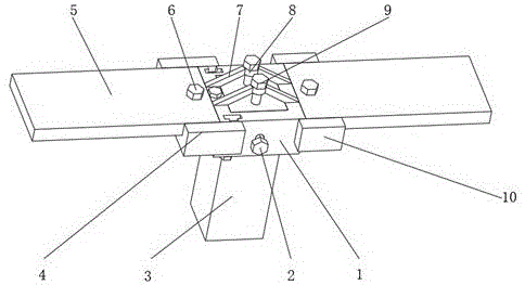
Fig. 1 is a schematic view of a combined structure of a detachable connecting device for a building steel structure provided by the present invention;
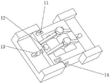
fig. 2 is a schematic view of a partial top view of a detachable connection device for a building steel structure according to the present invention;
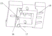
fig. 3 is the utility model provides a building steel structure's connection device can dismantle local structure sketch map from the bottom.
In the figure: 1-main member connecting piece, 2-longitudinal steel member connecting bolt, 3-longitudinal steel member, 4-first side member connecting piece, 5-transverse steel member, 6-transverse steel member connecting bolt, 7-first reinforcing rib, 8-adjusting ring, 9-adjusting bolt, 10-second side member connecting piece, 11-first sliding groove, 12-first limiting bolt, 13-second kidney-shaped hole, 14-first lug, 15-second lug, 16-second sliding groove, 17-second limiting bolt and 18-second reinforcing rib.
Detailed Description
The technical solutions in the embodiments of the present invention will be described clearly and completely with reference to the accompanying drawings in the embodiments of the present invention, and it is obvious that the described embodiments are only some embodiments of the present invention, not all embodiments.
In the description of the present invention, it is to be understood that the terms "upper", "lower", "front", "rear", "left", "right", "top", "bottom", "inner", "outer", and the like indicate orientations or positional relationships based on the orientations or positional relationships shown in the drawings, and are only for convenience of description and simplicity of description, and do not indicate or imply that the device or element being referred to must have a particular orientation, be constructed and operated in a particular orientation, and therefore, should not be construed as limiting the present invention.
A detachable connecting device of a building steel structure comprises a longitudinal steel member 3, two transverse steel members 5, a main member connecting member 1 for connecting the longitudinal steel member 3 and the transverse steel members 5, a first side member connecting member 4 and a second side member connecting member 10, wherein the main member connecting member 1 is provided with a first waist-shaped hole, the inner wall of the main member connecting member 1 is wrapped on the outer wall of the longitudinal steel member 3 and is fixedly connected with the longitudinal steel member 3 through a longitudinal steel connecting bolt 2, the inner walls of the first side member connecting member 4 and the second side member connecting member 10 are provided with a second waist-shaped hole 13, the two transverse steel members 5 are fixedly connected with the two second waist-shaped holes 13 respectively through transverse steel connecting bolts 6, the second side member connecting member 10 is fixedly welded with the main member connecting member 1, the first side member connecting member 4 is connected with the main member connecting member 1 in a sliding manner, a limiting component is arranged at the sliding connection part of the main structure connecting piece 1, and an adjusting component is arranged on the outer wall of the top of the main structure connecting piece; when in use, the main structure connecting piece 1 is firstly wrapped on the outer wall of the longitudinal steel member 3, then the main structure connecting piece 1 and the longitudinal steel member 3 are pre-tightened through the longitudinal steel structure connecting bolt 2, then two transverse steel members 5 are respectively placed on the outer walls of the tops of the first side structure connecting piece 4 and the second side structure connecting piece 10, and are pre-tightened through the transverse steel structure connecting bolt 6, then, according to the longitudinal error of the transverse steel member 5 placed on the second side structure connecting piece 10, error compensation is carried out through the adjusting component arranged at the top of the main structure connecting piece 1, after the compensation is finished, the longitudinal steel structure connecting bolt 2 is firstly screwed, then the transverse steel structure connecting bolt 6 on the second side structure connecting piece 10 is screwed, then according to the longitudinal construction error of the transverse steel member 5 placed on the first side structure connecting piece 4, the error is compensated through the sliding connection effect of the first side structure connecting piece 4 and the longitudinal steel member 3 and the limiting component, after the compensation is finished, the transverse steel structure connecting bolts 6 on the first side structure connecting pieces 4 are screwed up to complete the whole connection, the connecting device can firstly fix the transverse steel members 3 and the transverse steel members 5 which are transversely and longitudinally arranged, secondly, according to the actual construction situation, when the longitudinal steel members 3 only need to be connected with a single transverse steel member 5, the first side structure connecting pieces 4 and the corresponding limiting components can be detached, only the second side structure connecting pieces 10 are used for single connection, when the two transverse steel members 5 need to be connected, the first side structure connecting pieces 4 and the limiting components are installed, the two connections can be completed, the structure can be changed according to the actual connection requirement, the flexibility of the connecting device is improved, in addition, the longitudinal height construction errors of the two transverse steel members 5 can be respectively compensated through the adjusting components and the limiting components, the condition that the connection cannot be realized due to the construction errors is avoided, the construction efficiency greatly improved under the condition of ensuring the connection reliability of the device.
In order to compensate for the longitudinal construction error of one of the transverse steel members 5, as shown in fig. 1, the adjusting assembly comprises an adjusting ring 8 and an adjusting bolt 9, four first reinforcing ribs 7 are welded on the outer wall of the top of the main member connecting member 1, the outer wall of the adjusting ring 8 is welded on the outer walls of the two symmetrical first reinforcing ribs 7, the outer wall of the adjusting bolt 9 is connected to the inner wall of the adjusting ring 8 through threads, and the outer wall of the bottom of the adjusting bolt 9 is in contact with the outer wall of the top of the longitudinal steel member 3; when the construction longitudinal height error of the transverse steel member 5 on the second side member connecting piece 10 occurs, the position where the main member connecting piece 1 is contacted with the longitudinal steel member 3 can move, and the relative position of the main member connecting piece 1 and the longitudinal steel member 3 can be adjusted by screwing the adjusting bolt 9, so that the height of the second side member connecting piece 10 is adjusted, and the construction error can be compensated.
In order to compensate for the longitudinal construction error of another transverse steel member 5, as shown in fig. 1, 2 and 3, the limiting assembly includes a first limiting bolt 12 and a second limiting bolt 17, the inner wall of the main member connecting member 1 is respectively provided with a first sliding groove 11 and a second sliding groove 16, the outer wall of the first side member connecting member 4 is integrally formed with a first protruding block 14 and a second protruding block 15, the first protruding block 14 is in sliding connection with the first sliding groove 11, the second protruding block 15 is in sliding connection with the second sliding groove 16, the outer wall of the first limiting bolt 12 is in threaded connection with the inner wall of the main member connecting member 1 close to the second sliding groove 16, the outer wall of the second limiting bolt 17 is in threaded connection with the inner wall of the main member connecting member 1 close to the first sliding groove 11, and the first sliding groove 11, the first protruding block 14, the second protruding block 15 and the second sliding groove 16 are all in a T-shaped design; the first side structure connecting piece 4 and the main structure connecting piece 1 are mutually matched and slidably connected through a first sliding groove 11, a first convex block 14, a second convex block 15 and a second sliding groove 16, and are vertically limited through a first limiting bolt 12 and a second limiting bolt 17, so that the fixation of the first side structure connecting piece 4 and the main structure connecting piece 1 is ensured in sequence, when a longitudinal construction error occurs to a transverse steel member 5 on the first side structure connecting piece 4, the height position of the first side structure connecting piece 4 relative to the main structure connecting piece 1 can be adjusted through the tightness of the first limiting bolt 12 and the second limiting bolt 17, and the construction error can be compensated
For strengthening connection, as shown in fig. 3, the second side frame connecting member 10 is welded with the outer wall of the main frame connecting member 1 to form a second reinforcing rib 18; the second reinforcing ribs 18 can strengthen the connection strength of the second side member connecting piece 10 and the main member connecting piece 1, and the reliability of the device is ensured.
The working principle is as follows: when in use, the main structure connecting piece 1 is firstly wrapped on the outer wall of the longitudinal steel member 3, then the main structure connecting piece 1 and the longitudinal steel member 3 are pre-tightened through the longitudinal steel structure connecting bolt 2, then two transverse steel members 5 are respectively placed on the outer walls of the tops of the first side structure connecting piece 4 and the second side structure connecting piece 10, and are pre-tightened through the transverse steel structure connecting bolt 6, then, according to the longitudinal error of the transverse steel member 5 placed on the second side structure connecting piece 10, error compensation is carried out through the adjusting component arranged at the top of the main structure connecting piece 1, after the compensation is finished, the longitudinal steel structure connecting bolt 2 is firstly screwed, then the transverse steel structure connecting bolt 6 on the second side structure connecting piece 10 is screwed, then according to the longitudinal construction error of the transverse steel member 5 placed on the first side structure connecting piece 4, the error is compensated through the sliding connection effect of the first side structure connecting piece 4 and the longitudinal steel member 3 and the limiting component, after the compensation finishes, screw up the transverse steel structure connecting bolt 6 on the first side structure connecting piece 4, accomplish whole connection, when vertical steel member 3 only need connect single transverse steel member 5, can demolish first side structure connecting piece 4 and corresponding spacing subassembly, only utilize second side structure connecting piece 10 to carry out single connection, when needing to connect two transverse steel members 5, with first side structure connecting piece 4 and spacing unit mount, can accomplish two connections.
The above, only be the concrete implementation of the preferred embodiment of the present invention, but the protection scope of the present invention is not limited thereto, and any person skilled in the art is in the technical scope of the present invention, according to the technical solution of the present invention and the utility model, the concept of which is equivalent to replace or change, should be covered within the protection scope of the present invention.