CN212824435U - Ceramic composite board interlayer trimming device - Google Patents
Ceramic composite board interlayer trimming device Download PDFInfo
- Publication number
- CN212824435U CN212824435U CN202021275014.1U CN202021275014U CN212824435U CN 212824435 U CN212824435 U CN 212824435U CN 202021275014 U CN202021275014 U CN 202021275014U CN 212824435 U CN212824435 U CN 212824435U
- Authority
- CN
- China
- Prior art keywords
- trimming
- telescopic
- conveying
- guide
- ceramic composite
- Prior art date
- Legal status (The legal status is an assumption and is not a legal conclusion. Google has not performed a legal analysis and makes no representation as to the accuracy of the status listed.)
- Active
Links
Images

Abstract
The utility model belongs to the technical field of ceramic composite insulating brick processing machinery technique and specifically relates to a ceramic composite sheet intermediate layer deburring device is related to. The interlayer trimming device for the ceramic composite plate is arranged in an outer frame and comprises a conveying mechanism, a thickness adjusting mechanism, a pressing mechanism, a telescopic trimming mechanism, a guide mechanism and a dust removing mechanism, wherein the conveying mechanism is horizontally arranged in the middle of the outer frame, the pressing mechanism is arranged on a fixed rod at the upper end of the outer frame and transversely arranged above the conveying mechanism, the guide mechanism is arranged at a feed port of the conveying mechanism, the thickness adjusting mechanism is arranged above a feed inlet and a discharge outlet of the conveying mechanism, the telescopic trimming mechanism is arranged on two sides of the conveying mechanism, and the dust removing mechanism is arranged below the telescopic trimming mechanism. The utility model discloses an gain effect does: the ceramic composite brick trimming device has the advantages of good trimming effect, no damage to the edge of the surface of the ceramic brick, accurate positioning, high processing efficiency, capability of better ensuring the yield of the production of the ceramic composite brick, easy operation, environmental protection and safety.
Description
Technical Field
The utility model belongs to the technical field of ceramic composite insulating brick processing machinery technique and specifically relates to a ceramic composite sheet intermediate layer deburring device is related to.
Background
The ceramic composite heat insulation brick comprises a ceramic face brick, a foaming heat insulation layer and a bearing layer, wherein the foaming heat insulation layer is arranged between the ceramic face brick and the bearing layer, but the ceramic composite heat insulation brick is in the production and processing process, because the middle foaming heat insulation layer is in a fluid state before being heated and cured, the foaming heat insulation layer is easily extruded by the ceramic face brick and the bearing layer to flow to the left side and the right side of a blank brick, uneven burrs can be left on the two sides of a finished brick after heat treatment, the existing treatment method is to carry out manual trimming treatment after the brick is produced, the treatment mode not only needs to consume manpower and a large amount of working hours, has low production efficiency, but also cannot accurately grasp the trimming thickness by manpower, easily damages the ceramic face brick, influences the yield, the trimmed waste can also influence the body health of workers, and a device capable of quickly and accurately trimming the foaming waste heat insulation layers on the two sides of the finished composite brick is needed to solve the defects existing in the prior art .
Disclosure of Invention
An object of the utility model is to provide a can maintain compound ceramic brick edge fast, protect compound brick face and avoid the damage, automatic adaptation brick face width, operation safety ring protects's ceramic composite sheet intermediate layer deburring device to solve the weak point that above-mentioned prior art exists.
In order to achieve the above object, the utility model provides a following technical scheme:
the utility model provides a ceramic composite sheet intermediate layer deburring device, intermediate layer deburring device sets up in outer frame, intermediate layer deburring device includes conveying mechanism, thickness adjustment mechanism, presses material mechanism, flexible deburring mechanism, guiding mechanism and dust removal mechanism, the conveying mechanism level sets up the middle part at outer frame, press material mechanism to install and transversely set up in the conveying mechanism top on the dead lever of outer frame upper end, go out at conveying mechanism's feed port and be provided with guiding mechanism, thickness adjustment mechanism sets up the business turn over material mouth top at conveying mechanism, flexible deburring mechanism sets up in conveying mechanism's both sides, is equipped with dust removal mechanism in flexible deburring mechanism below.
Further, conveying mechanism is including carrying guide rail and carrying the deflector roll, carry the guide rail level along vertically setting both ends around carrying the deflector roll, be equipped with the conveying pulley in the middle of carrying the guide rail, the conveying pulley surface covers there is the slipmat, carry the horizontal middle part that sets up at the outer frame of deflector roll.
Further, thickness adjustment mechanism includes lift adjustment frame, adjusts the rotating part, and the material roller is led, rotates the installation slider, lift adjustment frame sets up both ends about carrying the deflector roll, rotate the sliding guide that the installation slider set up in lift adjustment frame on, it meets with adjusting the rotating part to rotate installation slider upper end, it passes lift adjustment frame top horizontal pole to adjust the rotating part upper end, adjust the rotating part and adopt threaded connection with lift adjustment frame, the tip setting is in two rotation installation sliders about the material roller, the material roller is carried the deflector roll and is aimed at parallel arrangement at same longitudinal plane.
Further, the pressure material mechanism includes the mounting panel, lower connecting plate and pressure material roller, go up the fixed dead lever that sets up in the outer frame upper end of mounting panel, go up the mounting panel and link to each other through altitude mixture control pole and the lower connecting plate that sets up at the dead lever lower extreme, the pressure material roller sets up terminal surface under the lower connecting plate, and the pressure material roller aligns parallel arrangement at same longitudinal plane with carrying the deflector roll.
Further, flexible deburring mechanism limit includes deburring emery wheel, deburring motor, removes base, flexible slide bar, and telescopic adjusting rod, width regulator, the deburring emery wheel sets up at deburring motor front end, the deburring motor is installed and is set up respectively on removing the base and carry the deflector roll left and right sides, it is equipped with slide opening and flexible guiding hole to remove the base below, it puts on two horizontal telescopic slide bars of placing through the slide opening cover to remove the base, flexible guiding hole is installed on telescopic adjusting rod, and flexible guiding hole and telescopic adjusting rod adopt screw-thread fit, telescopic adjusting rod stretches out the end and is connected with width regulator, is equipped with spacing inductor in telescopic adjusting rod one side.
Further, guiding mechanism includes the width adjustment base, the direction pole setting, the leading wheel, the width adjustment base outside is equipped with adjust knob, the leading wheel runs through to be installed in the direction pole setting, the direction pole setting sets up perpendicularly on the width adjustment base.
Furthermore, the dust removal mechanism comprises a waste material falling groove and a dust collector, a dust removal hole is formed in the bottom surface of the waste material falling groove, the lower end of the dust removal hole is connected with the dust collector through an air guide pipe, an upward arched arc-shaped filter screen is arranged above the dust removal hole, and the dust collector is connected to a waste material collection part.
Furthermore, the waste material falling groove is a V-shaped groove.
Furthermore, the contact surface of the guide wheel is an inwards concave arc surface, and the guide wheel is made of wear-resistant elastic rubber.
Compared with the prior art, the utility model discloses a gain effect does: the utility model discloses a material mechanism is pressed in cooperation of flexible deburring mechanism can repair the unnecessary waste material that ceramic composite heat insulating brick intermediate layer edge was extruded in production fast and stably, keep the edge of composite brick material level, can not cause the damage to the edge of ceramic brick face, the location is accurate, high machining efficiency, the yields of the production of assurance ceramic composite brick material that can be better, still be equipped with dust removal mechanism simultaneously, the marginal clout after avoiding repairing scatters the polluted environment, effectual protection workshop workman's health and the air circumstance who keeps in the workshop are clean, no dust pollution, high operation convenience, environmental protection and safety, the deburring practicality is strong, can be applicable to different ceramic tile combined material's deburring processing, wide application scope.
Drawings
Fig. 1 is a schematic structural view of the present invention;
fig. 2 is a schematic view of the trimming structure of the present invention.
Detailed Description
The present invention will be further described with reference to the following embodiments. Wherein the showings are for the purpose of illustration only and are shown by way of illustration only and not in actual form, and are not to be construed as limiting the present patent; for a better understanding of the embodiments of the present invention, some parts of the drawings may be omitted, enlarged or reduced, and do not represent the size of an actual product; it will be understood by those skilled in the art that certain well-known structures in the drawings and descriptions thereof may be omitted.
The same or similar reference numerals in the drawings of the embodiments of the present invention correspond to the same or similar parts; in the description of the present invention, it should be understood that if there are the terms "upper", "lower", "left", "right", etc. indicating the orientation or positional relationship based on the orientation or positional relationship shown in the drawings, it is only for convenience of description and simplification of the description, but it is not intended to indicate or imply that the device or element referred to must have a specific orientation, be constructed in a specific orientation, and be operated, and therefore the terms describing the positional relationship in the drawings are only for illustrative purposes and are not to be construed as limitations of the present patent, and those skilled in the art can understand the specific meanings of the terms according to specific situations.
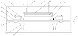
Please refer to fig. 1-2, which is a schematic structural diagram of the present invention, the present invention relates to a trimming device for an interlayer of a ceramic composite board, the trimming device for an interlayer is disposed in an outer frame 9, the trimming device for an interlayer comprises a conveying mechanism 1, a thickness adjusting mechanism 2, a material pressing mechanism 3, a telescopic trimming mechanism 4, a guiding mechanism 5 and a dust removing mechanism 6, the conveying mechanism 1 is horizontally disposed at the middle part of the outer frame 9, the material pressing mechanism 3 is transversely disposed above the conveying mechanism 1 on a fixing rod 91 disposed at the upper end of the outer frame 9, the guiding mechanism 5 is disposed at the outlet of the feeding port of the conveying mechanism 1, the thickness adjusting mechanism 2 is disposed above the feeding and discharging port of the conveying mechanism 1, the telescopic trimming mechanism 4 is disposed at two sides of the conveying mechanism 1, and the dust removing mechanism 6 is disposed below the telescopic trimming mechanism 4.
Further, conveying mechanism 1 is including carrying guide rail 11 and carrying deflector roll 12, carry guide rail 11 level along vertically setting at both ends around carrying deflector roll 12, be equipped with conveying pulley 13 in the middle of carrying guide rail 11, conveying pulley 13 surface covers there is the slipmat, carry deflector roll 12 level and transversely set up at the middle part of outer frame 9, send out the ceramic composite board of processing out through conveying mechanism 1 and handle to flexible deburring mechanism 4 to improve the efficiency of deburring.
Further, the thickness adjusting mechanism 2 comprises a lifting adjusting frame 21, an adjusting rotating part 22, a material guiding roller 23, a rotating installation slide block 24, the lifting adjusting frame 21 is arranged at the left end part and the right end part of the conveying guide roller 12, the rotary mounting slide block 24 is arranged on a sliding guide rail 25 in the lifting adjusting frame 21, the upper end part of the rotary mounting slide block 24 is connected with the adjusting and rotating part 22, the upper end part of the adjusting and rotating part 22 passes through the cross bar at the top part of the lifting adjusting frame 21, the adjusting and rotating part 22 is connected with the lifting adjusting frame 21 by screw thread, the left end and the right end of the material guiding roller 23 are arranged in two rotating and installing slide blocks 24, the material guiding roller 23 is aligned with the conveying guide roller 12 and arranged on the same longitudinal plane in parallel, the thickness of the ceramic composite board entering the telescopic trimming mechanism 4 is controlled and adjusted through the thickness adjusting mechanism 2, and meanwhile, the auxiliary fixing effect can be achieved.
Further, the material pressing mechanism 3 comprises an upper mounting plate 31, a lower connecting plate 32 and a material pressing roller 33, the upper mounting plate 31 is fixedly arranged on a fixing rod 91 at the upper end of the outer frame 9, the upper mounting plate 31 is connected with the lower connecting plate 32 arranged at the lower end of the fixing rod 91 through a height adjusting rod 34, the material pressing roller 33 is arranged on the lower end face of the lower connecting plate 32, the material pressing roller 33 is aligned with the conveying guide roller 12 and arranged on the same longitudinal plane in parallel, the material pressing mechanism 3 is adopted to fix and press the plates when the telescopic trimming mechanism 4 trims the left materials on the two sides of the ceramic composite plates, and the effect of trimming is prevented from being influenced by vibration of the plates.
Further, the side of the telescopic trimming mechanism 4 comprises a trimming grinding wheel 41, a trimming motor 42, a movable base 43, telescopic sliding rods 44, a telescopic adjusting rod 45 and a width adjuster 46, the trimming grinding wheel 41 is arranged at the front end of the trimming motor 42, the trimming motor 42 is arranged on the movable base 43 and is respectively arranged at the left side and the right side of the conveying guide roller 12, a sliding hole 47 and a telescopic guide hole 48 are arranged below the movable base 43, the movable base 43 is sleeved on the two transversely-arranged telescopic sliding rods 44 through the sliding hole 47, the telescopic guide hole 48 is arranged on the telescopic adjusting rod 45, the telescopic guide hole 48 is in threaded fit with the telescopic adjusting rod 45, the extending end of the telescopic adjusting rod 45 is connected with the width adjuster 46, a limit inductor 49 is arranged at one side of the telescopic adjusting rod 45, the telescopic trimming mechanism 4 can automatically adjust the width according to the width of the ceramic composite board fed in through the cooperation of each mechanism, meanwhile, the hardness of the material adopted by the trimming grinding wheel 41 is slightly lower than that of the ceramic brick surface, so that redundant waste materials on two sides of the plate can be quickly and effectively ground, the two sides of the ceramic brick surface can not be damaged, and the integral integrity of the ceramic composite plate is kept.
Further, the guide mechanism 5 comprises a width adjusting base 51, a guide vertical rod 52 and a guide wheel 53, an adjusting knob 54 is arranged on the outer side of the width adjusting base 51, the guide wheel 53 is installed on the guide vertical rod 52 in a penetrating mode, the guide vertical rod 52 is vertically arranged on the width adjusting base 51, the guide mechanism 5 is adopted to pre-adjust the position of the plate before the plate enters the telescopic trimming mechanism 4, and the two side edges of the plate are ensured to be kept in a parallel state with the telescopic trimming mechanism 4 when the plate enters the trimming mechanism 4.
Further, the dust removing mechanism 6 comprises a waste material dropping groove 61 and a dust collector 62, a dust removing hole 63 is formed in the bottom surface of the waste material dropping groove 61, the lower end portion of the dust removing hole 63 is connected with the dust collector 62 through an air guide pipe 64, an upward arched circular-arc-shaped filter screen 65 is arranged above the dust removing hole 63, the filter screen 65 is detachably mounted, the dust collector 62 is connected to a waste material collecting portion, trimmed waste materials and dust are sucked and collected to the waste material collecting portion to be treated, and the waste materials and the dust generated by trimming can be collected and treated in a centralized mode.
Preferably, the waste material falls groove 61 and is V type groove, and the waste material dust falls down along waste material fall groove 61 inner wall, directly is absorb by dust catcher 62, avoids the waste material to pile up, and convenient the washing, the environmental protection is clean.
Preferably, the contact surface of leading wheel 53 is indent arc-shaped face, can protect ceramic plate face about the compound brick body, avoids wearing and tearing and the intermediate layer expects to adhere to leading wheel 53 on, influences the direction effect of rectifying, leading wheel 53 material is wear-resisting elastic rubber.
In this embodiment, the ceramic composite board to be trimmed is fed to the conveying guide roller 12 by sliding via the conveying pulley 13, and is subjected to position correction adjustment by the guide roller 53 provided at the front end of the conveying guide roller 12, and is fed to trimming.
After finishing the position trimming of the plate, the plate enters a thickness adjusting mechanism 2 with the height of a guide roller 23 adjusted in advance, and is conveyed to a pressing mechanism 3, the plate is clamped and fixed by a pressing roller 33 and a conveying guide roller 12 in a matching way, the two sides of the plate are continuously advanced to be contacted with trimming grinding wheels 41, the distance between the trimming grinding wheels 41 at the two sides is controlled by a width adjuster 46 to rotate and match with a telescopic guide hole 48 to drive a movable base 43 to move on a telescopic sliding rod 44 for automatic adaptive adjustment, a trimming motor 42 drives the trimming grinding wheels 41 to open edging and trimming, waste materials generated by trimming fall down along the inner wall of a V-shaped waste material falling groove 6, dust is directly absorbed by a dust collector 62 through a dust removing hole 63, the waste materials are prevented from being accumulated, the cleaning is convenient, the environment is protected to be clean, wherein the filter screen 65 is in an upward arched arc shape, and the waste, affecting the dust removal effect.
After the trimming process, the ceramic composite plate is sent out by the guide mechanism 5 on the rear side through the conveying guide rail 11 and is collected and stored.
It is obvious that the above embodiments of the present invention are only examples for clearly illustrating the present invention, and are not limitations to the embodiments of the present invention. Other variations and modifications will be apparent to persons skilled in the art in light of the above description. And are neither required nor exhaustive of all embodiments. Any modification, equivalent replacement, and improvement made within the spirit and principle of the present invention should be included in the protection scope of the claims of the present invention.
Claims (9)
1. The interlayer trimming device for the ceramic composite plate is arranged in an outer frame (9), it is characterized in that the interlayer trimming device comprises a conveying mechanism (1), a thickness adjusting mechanism (2), a material pressing mechanism (3), a telescopic trimming mechanism (4), a guide mechanism (5) and a dust removing mechanism (6), the conveying mechanism (1) is horizontally arranged in the middle of the outer frame (9), the pressing mechanism (3) is arranged on a fixed rod (91) at the upper end of the outer frame (9) and transversely arranged above the conveying mechanism (1), a guide mechanism (5) is arranged at the outlet of the feed port of the conveying mechanism (1), the thickness adjusting mechanism (2) is arranged above the material inlet and the material outlet of the conveying mechanism (1), the telescopic trimming mechanisms (4) are arranged on two sides of the conveying mechanism (1), and dust removal mechanisms (6) are arranged below the telescopic trimming mechanisms (4).
2. The device for trimming the sandwich of the ceramic composite board according to claim 1, wherein the conveying mechanism (1) comprises a conveying guide rail (11) and a conveying guide roller (12), the conveying guide rail (11) is horizontally and longitudinally arranged at the front end and the rear end of the conveying guide roller (12), a conveying pulley (13) is arranged in the middle of the conveying guide rail (11), the outer surface of the conveying pulley (13) is covered with a non-slip mat, and the conveying guide roller (12) is horizontally and transversely arranged in the middle of the outer frame (9).
3. The trimming device for the sandwich of ceramic composite plates according to claim 1, the thickness adjusting mechanism (2) comprises a lifting adjusting frame (21), an adjusting rotating part (22), a material guiding roller (23) and a rotary mounting slide block (24), the lifting adjusting frames (21) are arranged at the left end and the right end of the conveying guide roller (12), the rotary mounting sliding blocks (24) are arranged on sliding guide rails (25) in the lifting adjusting frames (21), the upper end part of the rotary mounting slide block (24) is connected with the adjusting rotary part (22), the upper end part of the adjusting rotating part (22) passes through a cross bar at the top part of the lifting adjusting frame (21), the adjusting rotating part (22) is connected with the lifting adjusting frame (21) by screw thread, the left end and the right end of the material guide roller (23) are arranged in two rotary mounting sliding blocks (24), the guide roller (23) and the conveying guide roller (12) are aligned and arranged on the same longitudinal plane in parallel.
4. The device for trimming the interlayer of the ceramic composite plate as claimed in claim 1, wherein the pressing mechanism (3) comprises an upper mounting plate (31), a lower connecting plate (32) and a pressing roller (33), the upper mounting plate (31) is fixedly arranged on a fixing rod (91) at the upper end of the outer frame (9), the upper mounting plate (31) is connected with the lower connecting plate (32) arranged at the lower end of the fixing rod (91) through a height adjusting rod (34), the pressing roller (33) is arranged at the lower end face of the lower connecting plate (32), and the pressing roller (33) is aligned with the conveying guide roller (12) and arranged in parallel on the same longitudinal plane.
5. The device for trimming the interlayer of the ceramic composite plate according to claim 1, wherein the telescopic trimming mechanism (4) comprises a trimming grinding wheel (41), a trimming motor (42), a movable base (43), a telescopic sliding rod (44), a telescopic adjusting rod (45) and a width adjuster (46), the trimming grinding wheel (41) is arranged at the front end part of the trimming motor (42), the trimming motor (42) is arranged on the movable base (43) and is respectively arranged at the left side and the right side of the conveying guide roller (12), a sliding hole (47) and a telescopic guide hole (48) are arranged below the movable base (43), the movable base (43) is sleeved on the two transversely arranged telescopic sliding rods (44) through the sliding hole (47), the telescopic guide hole (48) is arranged on the telescopic adjusting rod (45), and the telescopic guide hole (48) is in threaded fit with the telescopic adjusting rod (45), the extension end of the telescopic adjusting rod (45) is connected with the width adjuster (46), and one side of the telescopic adjusting rod (45) is provided with a limit sensor (49).
6. The device for trimming the ceramic composite plate interlayer according to claim 1, wherein the guide mechanism (5) comprises a width adjusting base (51), a guide upright rod (52) and a guide wheel (53), an adjusting knob (54) is arranged on the outer side of the width adjusting base (51), the guide wheel (53) is penetratingly mounted on the guide upright rod (52), and the guide upright rod (52) is vertically arranged on the width adjusting base (51).
7. The device for trimming the sandwich of the ceramic composite plate according to claim 1, wherein the dust removing mechanism (6) comprises a waste material dropping groove (61) and a dust collector (62), a dust removing hole (63) is formed in the bottom surface of the waste material dropping groove (61), the lower end of the dust removing hole (63) is connected with the dust collector (62) through an air guide pipe (64), an upwardly arched circular-arc-shaped filter screen (65) is arranged above the dust removing hole (63), and the dust collector (62) is connected to a waste material collecting part.
8. The trimming device for the sandwich panel of ceramic composite plates according to claim 7, wherein the scrap chute (61) is a V-shaped chute.
9. The device for trimming the interlayer of the ceramic composite plate according to claim 6, wherein the contact surface of the guide wheel (53) is a concave arc surface, and the material of the guide wheel (53) is wear-resistant elastic rubber.
Priority Applications (1)
| Application Number | Priority Date | Filing Date | Title |
|---|---|---|---|
| CN202021275014.1U CN212824435U (en) | 2020-07-02 | 2020-07-02 | Ceramic composite board interlayer trimming device |
Applications Claiming Priority (1)
| Application Number | Priority Date | Filing Date | Title |
|---|---|---|---|
| CN202021275014.1U CN212824435U (en) | 2020-07-02 | 2020-07-02 | Ceramic composite board interlayer trimming device |
Publications (1)
| Publication Number | Publication Date |
|---|---|
| CN212824435U true CN212824435U (en) | 2021-03-30 |
Family
ID=75181018
Family Applications (1)
| Application Number | Title | Priority Date | Filing Date |
|---|---|---|---|
| CN202021275014.1U Active CN212824435U (en) | 2020-07-02 | 2020-07-02 | Ceramic composite board interlayer trimming device |
Country Status (1)
| Country | Link |
|---|---|
| CN (1) | CN212824435U (en) |
Cited By (1)
| Publication number | Priority date | Publication date | Assignee | Title |
|---|---|---|---|---|
| CN114654341A (en) * | 2022-04-01 | 2022-06-24 | 苏州锐美文化传媒有限公司 | Art design's ya keli trimmer for processing |
-
2020
- 2020-07-02 CN CN202021275014.1U patent/CN212824435U/en active Active
Cited By (1)
| Publication number | Priority date | Publication date | Assignee | Title |
|---|---|---|---|---|
| CN114654341A (en) * | 2022-04-01 | 2022-06-24 | 苏州锐美文化传媒有限公司 | Art design's ya keli trimmer for processing |
Similar Documents
| Publication | Publication Date | Title |
|---|---|---|
| CN208645535U (en) | A kind of non-woven fabrics trimming equipment of environment-friendly type | |
| CN212824435U (en) | Ceramic composite board interlayer trimming device | |
| CN109483353B (en) | Bamboo chip grinding device is used in bamboo basket production | |
| CN210679206U (en) | Environment-friendly building material cutting equipment | |
| CN112591508A (en) | Edge cutting device for producing non-woven fabric | |
| CN206764898U (en) | A kind of plastic pipe fitting cutting machine structure dust exhaust apparatus | |
| CN215589930U (en) | Automatic change waterproofing membrane production with flattening device | |
| CN216831652U (en) | Automatic stone cutting machine who removes dust | |
| CN113910042B (en) | Dysmorphism backlight board cutting edging all-in-one | |
| CN213648171U (en) | Ceramic tile cutting production line | |
| CN110983930A (en) | Road surface marking line clearing device | |
| CN210498858U (en) | Cloth deckle edge processing apparatus based on computer control | |
| CN107639287A (en) | A kind of bidirectional electric cutting machine | |
| CN208801388U (en) | A kind of light guide plate cutter device of dust removal | |
| CN206519367U (en) | A kind of glass wheat flour purifier on glass production line | |
| CN220882444U (en) | Soft sand paper and segmentation equipment thereof | |
| CN108788909A (en) | A kind of safety device of mechanical equipment | |
| CN216265302U (en) | Polishing device for sawing flat steel | |
| CN213867041U (en) | Edge cutting device for spunlace nonwoven fabric | |
| CN112677015B (en) | Full-automatic saw cutting production line for oblique angle of handlebar vertical pipe and production process thereof | |
| CN218612040U (en) | Inclination adjusting type cutting device for plate production | |
| CN220614157U (en) | Waterproof sheet slitting device | |
| CN216606453U (en) | Plate surface saw-dust cleaning device | |
| CN220466991U (en) | LED lamp strip paster processing tool | |
| CN219854752U (en) | Cutting mechanism of coated paper |
Legal Events
| Date | Code | Title | Description |
|---|---|---|---|
| GR01 | Patent grant | ||
| GR01 | Patent grant |