CN212819669U - Digital storage batching system for industrial granular powder - Google Patents
Digital storage batching system for industrial granular powder Download PDFInfo
- Publication number
- CN212819669U CN212819669U CN202020965038.3U CN202020965038U CN212819669U CN 212819669 U CN212819669 U CN 212819669U CN 202020965038 U CN202020965038 U CN 202020965038U CN 212819669 U CN212819669 U CN 212819669U
- Authority
- CN
- China
- Prior art keywords
- hopper
- negative pressure
- granular powder
- hoppers
- blanking
- Prior art date
- Legal status (The legal status is an assumption and is not a legal conclusion. Google has not performed a legal analysis and makes no representation as to the accuracy of the status listed.)
- Active
Links
Images


Landscapes
- Filling Or Emptying Of Bunkers, Hoppers, And Tanks (AREA)
Abstract
A digital storage and batching system for industrial granular powder. The utility model relates to a solve prior art and have links such as storage, transport, measurement unloading and compounding of enterprise grain powder to have intensity of labour high, the big scheduling problem of error of storing and taking the material. The technical points are as follows: the device is characterized by comprising a plurality of groups of storage bins, a plurality of groups of blanking batching units, a plurality of groups of production negative pressure blanking suction hoppers and an air pressure vacuum machine station, wherein the group of blanking batching units comprises a plurality of intermediate negative pressure blanking suction hoppers, a plurality of blanking hoppers, a stirring mixing hopper and a mixing temporary storage hopper, the production negative pressure blanking suction hoppers are arranged on production equipment, the storage bins are connected with the blanking batching units and the production negative pressure blanking suction hoppers, the storage bins are connected with the intermediate negative pressure blanking suction hoppers, the mixing temporary storage hopper is connected with the production negative pressure blanking suction hoppers, the air pressure vacuum machine station is connected with the production negative pressure blanking suction hoppers and the intermediate negative pressure blanking suction hoppers, the storage bins and the blanking hoppers are provided with automatic weighing frames, and an automatic control valve is arranged on a granular powder conveying pipeline.
Description
Technical Field
The utility model relates to an automatic supply technology of industrial granule material and/or powder, especially a digital storage feed proportioning system that can realize multiple industrial granule powder.
Background
In many industrial enterprises at present, daily production needs a large amount of industrial granules or powder. However, the links of weighing, storing, quantitatively conveying, metering, blanking, mixing and the like of the industrial granular materials or powder materials do not have digitalized full-automatic operation, so that the labor intensity of workers is high, the errors of storing and taking the materials are large, and obvious adverse effects are caused on raw material management and product quality.
Chinese patent No. 201720884036.X, previously applied by the present applicant, discloses a multifunctional accurate weighing, stirring and conveying system, the structure includes a weighing, stirring and feeding device and a powdery material feeding device connected to the weighing, stirring and feeding device, the powdery material feeding device includes a storage hopper, a vibration disc obliquely arranged below an outlet of the storage hopper, and the vibration disc is provided with a discharge nozzle. However, this solution has many improvements and is not suitable for digital storage and batching systems for various industrial granules or powders.
The Chinese patent application No. 201811472252.9 previously filed by the applicant discloses a multifunctional central feeding and conveying system, which structurally comprises a plurality of storage bins, a plurality of production main machines, a main pipe respectively communicated with the storage bins, a plurality of branch pipes respectively communicated with the production main machines and the main pipe, and a vacuum unit; switch valves are respectively arranged between the main pipe and the plurality of bins, and switch valves are respectively arranged between the main pipe and the plurality of branch pipes; the vacuum unit is in ventilation connection with the main pipe through an air distribution valve, the air distribution valve comprises an air suction chamber and an air blowing chamber, an air suction port of the vacuum unit is in ventilation connection with the air suction chamber, an air blowing port of the vacuum unit is in ventilation connection with the air blowing chamber, the air suction chamber is provided with an air suction pipe communicated with the outside, the air blowing chamber is provided with an air blowing pipe communicated with the outside, the air suction chamber and the air blowing chamber are respectively in ventilation connection with one end of the air blowing pipe, the other end of the air blowing pipe is in ventilation connection with the main pipe, switch valves are respectively arranged among the air suction pipe, the air blowing pipe and the air suction chamber, and switch valves are respectively arranged among the air suction pipe; the multi-stage cyclone separation device is arranged between the branch pipe and the production host, the multi-stage cyclone separation device comprises multi-stage cyclone separators and a hopper, discharge ports of the multi-stage cyclone separators are respectively communicated with the hopper, an air inlet of a first-stage cyclone separator is used as a device feeding port and communicated with the branch pipe, an air outlet of the first-stage cyclone separator is communicated with an air inlet of a second-stage cyclone separator, an air outlet of the second-stage cyclone separator is communicated with an air inlet … … of a third-stage cyclone separator, a structure in which the multi-stage cyclone separators are connected in series is sequentially formed, and an air outlet of the last-stage cyclone separator is used as a device exhaust port. However, this solution only solves the gas delivery principle structure on the central feed delivery system, and does not solve many problems of the integrated digital storage and batching system device.
Disclosure of Invention
In order to overcome prior art and can not provide the digital storage feed proportioning system device of multiple industrial granule material or powder, the great problem of error that artifical intensity of labour is high, storage and take the material all exists in links such as storage, transport, measurement unloading and compounding of the granule material that industrial enterprise daily production needs, the utility model aims at providing a digital storage feed proportioning system of modified industrial granule powder, can overcome prior art's defect.
The utility model provides a technical scheme that its technical problem adopted is: the utility model provides a digital storage feed proportioning system of industry grain powder, characterized by: the device comprises a plurality of groups of storage bins, a plurality of groups of discharging and batching units, a plurality of groups of production negative pressure discharging suction hoppers and an air pressure vacuum machine station, wherein each group of storage bins is provided with a plurality of storage bins, each group of discharging and batching units is provided with a plurality of intermediate negative pressure discharging suction hoppers, a plurality of discharging hoppers, a stirring and mixing hopper and a mixing temporary storage hopper which are arranged in a matching way from top to bottom, each group of production negative pressure discharging suction hoppers is provided with a plurality of production negative pressure discharging suction hoppers, each production negative pressure discharging suction hopper is arranged on a corresponding feed port of production equipment, each group of storage bins is correspondingly connected and matched with one group of discharging and batching units and one group of production negative pressure discharging suction hoppers, and a discharge port of each storage bin is connected with a feed port of one intermediate negative pressure discharging suction hopper in the discharging and batching units through a granular powder conveying pipeline for feeding, each the discharge gate that the compounding was kept in the fill all through a granule powder pipeline respectively with correspond all production negative pressure unloading suction hopper's in a set of production negative pressure unloading suction hopper feed inlet is connected, the air inlet of atmospheric pressure vacuum machine station passes through trachea and all production negative pressure unloading suction hopper with the gas outlet of middle negative pressure unloading suction hopper is connected, all the storage silo with the hopper is equallyd divide and is do not provided with the automatic weighing frame down, each the storage silo with correspond and be connected between the middle negative pressure unloading suction hopper, each between the middle negative pressure unloading suction hopper with correspond the complex between the hopper, each the hopper with correspond the complex between the stirring and mixing hopper, each stirring and mixing hopper with correspond the complex between the compounding is kept in between the hopper and correspond a set of production negative pressure unloading suction hopper all be equipped with the automatic control valve on the granule powder pipeline.
The technical scheme is that each blanking batching unit can be one of the middle negative pressure blanking suction hopper and one of the middle negative pressure blanking suction hopper are arranged in a matched mode from top to bottom, each of the middle negative pressure blanking suction hopper and the stirring mixing hopper are arranged in a matched mode from top to bottom, and the stirring mixing hopper and the mixing temporary storage hopper are arranged in a matched mode from top to bottom.
According to the technical scheme, all the blanking batching units can be provided with a main blanking hopper which is suitable for a large amount of main granular powder, an intermediate hopper can be arranged between the main blanking hopper and the stirring and mixing hopper in a matched mode, and automatic control valves are arranged on granular powder conveying pipelines between the main blanking hopper and the intermediate hopper which is matched with the main blanking hopper in a corresponding mode, and between the intermediate hopper and the stirring and mixing hopper which is matched with the intermediate hopper in a corresponding mode.
According to the technical scheme, the automatic control valve between the storage bin and the intermediate negative pressure blanking suction hopper which is correspondingly connected can be a granular powder conveying switch valve with a simple air inlet function structure. The pure air inlet functional structure ensures that the grain powder conveying pipeline between the storage bin and the middle negative pressure discharging suction hopper which is correspondingly connected can be cleaned by utilizing negative pressure gas after feeding, so that a small amount of materials adhered to the pipe wall of the grain powder conveying pipeline in the conveying process can be timely removed into the discharging hopper, the discharging accuracy is achieved, and the pure air inlet functional structure can also be prepared for avoiding the mixing of materials when different grains of powder are conveyed next time.
According to the technical scheme, the automatic control valve between the mixing temporary storage hopper and the production negative pressure discharging suction hopper which is correspondingly matched can be formed by connecting a granular powder conveying switch valve with a simple air inlet function structure and an N-position N +1 through granular powder conveying reversing valve in series. The pure air inlet function structure of the granular powder conveying switch valve with the pure air inlet function structure is to ensure that the granular powder conveying pipeline between the mixing material temporary storage hopper and a group of production negative pressure discharging suction hoppers which are correspondingly matched can be cleaned by negative pressure gas after feeding, so that a small amount of materials adhered to the pipe wall of the granular powder conveying pipeline in the conveying process can be timely removed to enter a feeding hole of production equipment, the discharging is more accurate, and the pure air inlet function structure can also provide for avoiding the mixing of materials when different granular powders are conveyed next time; the N-bit N +1 particle-passing powder conveying reversing valve is used for realizing that the material mixing temporary storage hopper carries out material conveying distribution on any one of the production negative pressure blanking suction hoppers.
According to the technical scheme, the automatic control valve between the mixing temporary storage hopper and the corresponding matched group of production negative pressure discharging suction hoppers can be composed of an N-position N +1 particle conveying reversing valve and particle powder conveying switch valves with simple air inlet function structures, wherein the particle powder conveying switch valves are respectively connected to the N-position N +1 particle conveying reversing valve and each particle powder conveying pipeline between the production negative pressure discharging suction hoppers. The N-position N +1 particle powder conveying reversing valve is used for realizing the purpose that the material mixing temporary storage hopper carries out material conveying distribution on any one production negative pressure discharging suction hopper, and each particle powder conveying switching valve with a simple air inlet function structure on a particle powder conveying pipeline of the production negative pressure discharging suction hopper has the advantages that the single air inlet function structure is used for enabling the particle powder conveying pipeline between the N-position N +1 particle powder conveying reversing valve and the corresponding production negative pressure discharging suction hopper to be cleaned by negative pressure gas after feeding, so that a small amount of materials adhered to the pipe wall of the particle powder conveying pipeline in the conveying process can be timely removed into a feeding hole of production equipment, the discharging accuracy is improved, and the preparation can be made for avoiding material mixing when different particle powders are conveyed next time.
According to the technical scheme, the granular powder conveying switch valve with the pure air inlet functional structure can adopt a three-position four-way reversing valve, wherein each gear is provided with a feed inlet, an air inlet, a discharge opening and a discharge closing, one gear is used for closing the granular powder conveying channel, the other gear is used for opening the granular powder conveying channel, and the other gear is used for pure air inlet under the condition of closing the granular powder conveying channel.
The air pressure vacuum machine station can be provided with more than two air pressure vacuum working machine sets to adapt to different requirements of providing different negative pressure requirements, and can also be provided with one air pressure vacuum storage machine set.
According to the technical scheme, an automatic control valve can be arranged on an air pipe between an air inlet of the air pressure vacuum machine station and an air outlet of the production negative pressure blanking suction hopper or the middle negative pressure blanking suction hopper.
The automatic control valve in the technical scheme can adopt any practical automatic control mode.
The valve or valve gate or gate according to the above technical solution is an equivalent technical feature, and the valve or valve may adopt any suitable structural form.
In the technical scheme, N of the N bit N +1 is any natural number more than 2.
The working principle of the production negative pressure blanking suction hopper and the intermediate negative pressure blanking suction hopper in the technical scheme can refer to the relevant content of the Chinese patent No. 201720884036.X and the Chinese patent application No. 201811472252.9 of the applicant.
The digital storage batching system for the industrial granular powder in the technical scheme can also be provided with a central console, and digital real-time system management is carried out on each warehousing, ex-warehouse, blanking and batching of the material through the video of the central console; according to the technical scheme, the digital storage and batching system for industrial granular powder can also be provided with a quantitative distribution digital display to digitally observe the material distribution condition between each mixing material temporary storage hopper and a group of production negative pressure blanking suction hoppers correspondingly matched with the mixing material temporary storage hopper.
The utility model has the advantages that: firstly, because the storage silo is equipped with a plurality of group, every group has a plurality of, material batching unit is equipped with a plurality of group, every group has hopper under a plurality of, every hopper is connected a storage silo and is accepted the grain powder material of carrying the provision down, every storage silo and every hopper all are provided with the automatic weighing frame down respectively, so the car is every with material filling to the storage silo in or from the material of storage silo per time the material of seeing off, the material of any hopper receipt every time or the material of output every time down, the batching of any stirring thoughtlessly hopper every time, all can carry out digital accurate measurement in real time, and the screen display is looked to the accessible, the warehousing of each time to the material has been realized, the delivery, the unloading, the batching all obtains digital real-time system management. Secondly because each the storage silo with correspond the connection between the middle negative pressure unloading suction hopper, each middle negative pressure unloading suction hopper with correspond the complex down between the hopper, each down the hopper with correspond the complex between the stirring mixing hopper, each stirring mixing hopper with correspond the complex between the compounding is kept in the hopper, each the compounding is kept in the hopper and is corresponded between a set of production negative pressure unloading suction hopper of complex all be equipped with the automatic control valve on the grain powder conveying pipeline, so can realize automated control and regulation to the material transport of each link of complicated digital storage feed proportioning system. Thirdly, the digitalized storage and batching system is used for weighing, storing, quantitatively conveying, metering, blanking and mixing industrial granules or powder supplied to a plurality of working equipment stations in a systematic and digitalized automatic manner, so that the labor intensity of workers is greatly reduced, errors in material storage and material taking are greatly reduced, and the production efficiency and the product quality of each working equipment station are effectively improved. And fourthly, because the automatic control valve between the storage bin and the correspondingly connected middle negative pressure discharging suction hopper can be set as a granular powder conveying switch valve with a simple air inlet function structure, the granular powder conveying pipeline between the storage bin and the correspondingly connected middle negative pressure discharging suction hopper can be cleaned by utilizing negative pressure gas after feeding through the simple air inlet function structure, a small amount of materials adhered to the pipe wall of the granular powder conveying pipeline in the conveying process can be timely removed into the discharging hopper, the discharging accuracy is improved, and the preparation can be prepared for preventing materials from being mixed when different granular powders are conveyed next time. Fifthly, because the automatic control valve between the mixing temporary storage hopper and the corresponding matched group of production negative pressure blanking suction hoppers can be set to be formed by connecting a grain powder conveying switch valve with a simple air inlet function structure and an N-position N +1 through grain powder conveying reversing valve in series, or a N-position N +1 through grain powder conveying reversing valve and a grain powder conveying switch valve with a simple air inlet function structure which is respectively connected on the N-position N +1 through grain powder conveying reversing valve and a grain powder conveying pipeline between the production negative pressure blanking suction hoppers, the grain powder conveying pipeline between the mixing temporary storage hopper and the corresponding matched group of production negative pressure blanking suction hoppers can be cleaned by using negative pressure gas after feeding through the simple air inlet function structure, so that a small amount of materials adhered to the pipe wall of the grain powder conveying pipeline in the conveying process can be timely cleaned and fed into a feed port of production equipment, the blanking is more accurate, and the preparation can be made for avoiding the mixing of materials when different powder grains are conveyed next time.
The invention is further described with reference to the following figures and examples.
Drawings
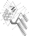
Fig. 1 is a schematic diagram of an embodiment of the present invention.
FIG. 2 is an enlarged schematic view of the combination of a group of storage silos and a group of blanking ingredient units of FIG. 1.
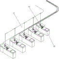
Fig. 3 is an enlarged schematic view of a set of production sub-atmospheric pressure blanking hoppers of fig. 1 cooperating with the set of blanking dosing units of fig. 2.
FIG. 4 is a diagrammatic, symbolic illustration of the automatically controlled valve between one of the storage silos of FIG. 1 and a correspondingly connected intermediate negative pressure feed hopper.
Fig. 5 is a schematic diagram of a graphical symbol of an automatic control valve between a mixing material temporary storage hopper and a group of production negative pressure blanking suction hoppers which are correspondingly matched in fig. 1.
Fig. 6 is a schematic diagram of a graphical symbol of another automatic control valve between a mixing material temporary storage hopper and a group of production negative pressure blanking suction hoppers matched with the mixing material temporary storage hopper in fig. 1.
In the figure: 1. a plurality of groups of storage bins; 2. a plurality of groups of blanking and batching units; 3. a plurality of groups of production negative pressure blanking suction hoppers; 4. a pneumatic vacuum station; 5. a storage bin; 6. 7 and 8, an intermediate negative pressure blanking suction hopper; 9. 10 and 11, a discharge hopper; 12. stirring the mixing hopper; 13. a temporary mixed material storage hopper; 14. producing a negative pressure blanking suction hopper; 15. production equipment; 16. 17, 18 and 19, an automatic weighing rack; 20. 21, 22, 23 and 24, automatic control valves; 25. a middle hopper; 26 and 27, automatic control valves; 28. a simple air intake functional structure (air intake); 29. a function structure of pure air intake; 30. a granular powder conveying switch valve; 31. a five-position six-way powder conveying reversing valve; 32. a five-position six-way powder conveying reversing valve; 33. a function structure of pure air intake; 34. a granular powder conveying switch valve; 35. a feed inlet; 36. a discharge opening; 37. the discharging and closing opening; 38 and 39, air pressure vacuum working machine set; 40. an air pressure vacuum storage unit; 41. automatically controlling the valve; 42. a central console; 43. a quantitative dispensing digital display.
Detailed Description
Referring to fig. 1 to 3, the digital storage and batching system for industrial granular powder is characterized in that: including a plurality of groups of storage silos 1 etc, a plurality of groups of unloading batching units 2 etc, a plurality of groups production negative pressure unloading suction hopper 3 etc. and an atmospheric pressure vacuum machine station 4, wherein every group storage silo 1 all is equipped with a plurality of storage silos 5 etc, each group unloading batching unit 2 all has from the top down the cooperation set up in the middle of a plurality of negative pressure unloading suction hopper 6, 7, 8 etc, a plurality of unloading hopper 9, 10, 11 etc, a stirring mixing hopper 12 and a compounding hopper 13 of keeping in, each group production negative pressure unloading suction hopper 3 all is equipped with a plurality of production negative pressure unloading suction hopper 14 etc. and each production negative pressure unloading suction hopper 14 all sets up on the feed inlet of a corresponding production facility 15 etc. each group storage silo 1 all with a set of unloading batching unit 2 and a set of production negative pressure unloading suction hopper 3 corresponds the connection cooperation, each the discharge gate of storage silo 5 all through powder conveying pipeline with correspond one in unloading batching unit 2 The feed inlet of middle negative pressure unloading suction hopper 7 is made the feed and is connected, each the discharge gate of compounding temporary storage hopper 13 all through granule powder conveying pipe respectively with correspond all production negative pressure unloading suction hopper 14 etc. in a set of production negative pressure unloading suction hopper 3 feed inlets connect, the air inlet of atmospheric pressure vacuum machine station 4 passes through the trachea and all production negative pressure unloading suction hopper 14 etc. with the gas outlet of middle negative pressure unloading suction hopper 6, 7, 8 etc. is connected, all storage silo 5 etc. with lower hopper 9, 10, 11 etc. divide equally and are provided with automatic weighing frame 16 etc. and 17, 18, 19 etc. respectively, each storage silo 5 with correspond the connection between middle negative pressure unloading suction hopper 6, each between middle negative pressure unloading suction hopper 6 and the corresponding complex lower hopper 9, each lower hopper 9 with correspond the complex between stirring and mixing hopper 12, Automatic control valves 20, 21, 22, 23 and 24 are arranged on the grain powder conveying pipeline between each stirring and mixing hopper 12 and the corresponding matched mixing temporary storage hopper 13 and between each mixing temporary storage hopper 13 and the corresponding matched group of production negative pressure blanking suction hoppers 3.
In addition, each of the intermediate negative pressure discharging suction hoppers 6, 7 and 8 and the corresponding one of the discharging hoppers 9, 10 and 11 are arranged in a top-down matching manner in the blanking batching unit 2, each of the discharging hoppers 9, 10 and 11 is arranged in a top-down matching manner in the stirring and mixing hopper 12, and the stirring and mixing hopper 12 and the mixing temporary storage hopper 13 are arranged in a top-down matching manner.
The main blanking hopper 10 is arranged in the blanking hoppers 9, 10 and 11 of the blanking batching units 2, and is suitable for the operation of a large number of main granular powder materials, an intermediate hopper 25 is also arranged between the main blanking hopper 10 and the stirring and mixing hopper 12 in a matching manner, and automatic control valves 26 and 27 are arranged on the granular powder material conveying pipeline between the main blanking hopper 10 and the intermediate hopper 25 correspondingly matched with the main blanking hopper, and between the intermediate hopper 25 and the stirring and mixing hopper 12 correspondingly matched with the intermediate hopper 25.
Referring to fig. 2 and 4, the automatic control valve 20 between the storage bin 5 and the corresponding connected intermediate negative pressure discharging suction hopper 6 is a granular powder conveying switch valve with a simple air inlet function structure 28 as shown in fig. 4. The pure air inlet functional structure 28 is to clean the granular powder conveying pipeline between the storage bin 5 and the intermediate negative pressure discharging suction hopper 6 connected correspondingly by using negative pressure gas after feeding, so that a small amount of materials adhered to the pipe wall of the granular powder conveying pipeline during conveying are removed into the discharging hopper 9 in time, more accurate discharging is achieved, and preparation can be made for avoiding material mixing when different granular powders are conveyed next time.
Referring to fig. 2 and 5, the automatic control valve 24 between the mixing temporary storage hopper 13 and a group of production negative pressure discharging suction hoppers 3 which are correspondingly matched is formed by connecting a granular powder conveying switch valve 30 with a simple air inlet function structure 29 and a five-position six-way granular powder conveying reversing valve 31 in series. The pure air inlet function structure 29 of the granular powder conveying switch valve 30 with the pure air inlet function structure 29 is to enable the granular powder conveying pipeline between the mixing material temporary storage hopper 13 and the corresponding matched group of production negative pressure blanking suction hoppers 3 to be cleaned by negative pressure gas after feeding, so that a small amount of materials adhered to the pipe wall of the granular powder conveying pipeline in the conveying process are timely removed to feed inlets of production equipment 15 and the like, more accurate blanking is achieved, and preparation can be made for avoiding material mixing when different granular powders are conveyed next time; the five-position six-way particle powder conveying reversing valve 31 is used for realizing the material conveying and distribution of the mixing temporary storage hopper 13 to any one production negative pressure blanking suction hopper 14 and the like.
Referring to fig. 2 and 6, the automatic control valve 24 between the temporary mixing storage hopper 13 and the corresponding set of production negative pressure discharging suction hoppers 3 is composed of a five-position six-way granular powder conveying reversing valve 32, five granular powder conveying switching valves 34 with a simple air inlet function structure 33 and the like, which are respectively connected to granular powder conveying pipelines between the five-position six-way granular powder conveying reversing valve 32 and the five production negative pressure discharging suction hoppers 14 and the like. The five-position six-way granular powder conveying reversing valve 32 is used for realizing the purpose that the mixing temporary storage hopper 13 conveys and distributes materials to any one production negative pressure blanking suction hopper 14, the five granular powder conveying switch valves 34 with a simple air inlet function structure 33 and the like on the granular powder conveying pipelines of the five production negative pressure blanking suction hoppers 14 and the like, and the simple air inlet function structure 34 is used for cleaning the granular powder conveying pipelines between the five-position six-way granular powder conveying reversing valve 32 and the corresponding production negative pressure blanking suction hopper 14 after feeding by using negative pressure gas, so that a small amount of materials adhered to the pipe wall of the granular powder conveying pipeline in the conveying process can be timely removed into the feeding ports of production equipment 15 and the like, the blanking is more accurate, and the preparation can be made for avoiding the mixing of the materials when different granular powders are conveyed next time.
Referring to fig. 4, the granular powder conveying switch valve 20 with the simple air inlet function structure 28 adopts a three-position four-way reversing valve, wherein each gear position has an inlet 35, an inlet 28, an outlet opening 36 and an outlet closing 37. When the granular powder conveying switch valve 20 is at the 2 nd position, the granular powder conveying channel is closed; when the granular powder conveying switch valve 20 is at the 3 rd position, the granular powder conveying channel is opened; when the granular powder conveying switch valve 20 is at the 1 st position, the granular powder conveying passage is closed, and the pure air inlet passage is opened. The construction principles of the granular powder conveying switch valve 30 with the simple air intake function structure 29 of fig. 5 and the five granular powder conveying switch valves 34 with the simple air intake function structures 33 and the like of fig. 6 are the same as those of the granular powder conveying switch valve 20 with the simple air intake function structure 28 of fig. 4, and will not be described separately.
The pneumatic vacuum machine station 4 is provided with two pneumatic vacuum working units 38 and 39 to meet different requirements of providing different negative pressure requirements, and a pneumatic vacuum storage unit 40.
An automatic control valve 41 is arranged on an air pipe between an air inlet of the pneumatic vacuum machine station 38 and an air outlet of the production negative pressure blanking suction hopper 14 or the like or the middle negative pressure blanking suction hopper 6 or the like.
The digital storage and batching system for the industrial granular powder is also provided with a central console 42, and digital real-time system management on each warehousing, ex-warehousing, blanking and batching of the material is realized through videos on the central console 42; the digital storage and batching system for industrial granular powder is also provided with a quantitative distribution digital display 43, so that the digital observation of the material distribution condition between each mixing temporary storage hopper 13 and a group of production negative pressure blanking suction hoppers 14 and the like correspondingly matched with the mixing temporary storage hopper is realized.
Claims (10)
1. The utility model provides a digital storage feed proportioning system of industry grain powder, characterized by: the device comprises a plurality of groups of storage bins, a plurality of groups of discharging and batching units, a plurality of groups of production negative pressure discharging suction hoppers and an air pressure vacuum machine station, wherein each group of storage bins is provided with a plurality of storage bins, each group of discharging and batching units is provided with a plurality of intermediate negative pressure discharging suction hoppers, a plurality of discharging hoppers, a stirring and mixing hopper and a mixing temporary storage hopper which are arranged in a matching way from top to bottom, each group of production negative pressure discharging suction hoppers is provided with a plurality of production negative pressure discharging suction hoppers, each production negative pressure discharging suction hopper is arranged on a corresponding feed port of production equipment, each group of storage bins is correspondingly connected and matched with one group of discharging and batching units and one group of production negative pressure discharging suction hoppers, and a discharge port of each storage bin is connected with a feed port of one intermediate negative pressure discharging suction hopper in the discharging and batching units through a granular powder conveying pipeline for feeding, each the discharge gate that the compounding was kept in the fill all through a granule powder pipeline respectively with correspond all production negative pressure unloading suction hopper's in a set of production negative pressure unloading suction hopper feed inlet is connected, the air inlet of atmospheric pressure vacuum machine station passes through trachea and all production negative pressure unloading suction hopper with the gas outlet of middle negative pressure unloading suction hopper is connected, all the storage silo with the hopper is equallyd divide and is do not provided with the automatic weighing frame down, each the storage silo with correspond and be connected between the middle negative pressure unloading suction hopper, each between the middle negative pressure unloading suction hopper with correspond the complex between the hopper, each the hopper with correspond the complex between the stirring and mixing hopper, each stirring and mixing hopper with correspond the complex between the compounding is kept in between the hopper and correspond a set of production negative pressure unloading suction hopper all be equipped with the automatic control valve on the granule powder pipeline.
2. The digital storage and batching system for industrial granular powder as claimed in claim 1, wherein a set of said blanking batching units is provided with each of said intermediate negative pressure blanking suction hoppers matching with one of said blanking hoppers from top to bottom, each of said blanking hoppers matching with one of said stirring and mixing hoppers from top to bottom, and each of said stirring and mixing hoppers matching with one of said mixing temporary hoppers from top to bottom.
3. The digital storage and batching system for industrial granular powder as claimed in claim 1 or 2, wherein a main blanking hopper is arranged in all the blanking hoppers of a group of blanking batching units, and is suitable for a large number of main granular powder, an intermediate hopper can be arranged between the main blanking hopper and the stirring and mixing hopper in a matching manner, and automatic control valves are arranged on the granular powder conveying pipelines between the main blanking hopper and the corresponding matched intermediate hopper and between the intermediate hopper and the corresponding matched stirring and mixing hopper.
4. The digital storage and batching system for industrial granular powder as claimed in claim 1 or 2, wherein the automatic control valve between the storage bin and the corresponding intermediate negative pressure discharge suction hopper is a granular powder conveying switch valve with a simple air intake function structure, wherein the simple air intake function structure is to enable the granular powder conveying pipeline between the storage bin and the corresponding intermediate negative pressure discharge suction hopper to be cleaned by negative pressure gas after feeding, so that a small amount of material adhered to the pipe wall of the granular powder conveying pipeline during conveying can be timely removed into the discharge hopper, thereby achieving more precise discharging and providing no need of material mixing when different granular powder is conveyed next time.
5. The digital storage and batching system for industrial granular powder materials according to claim 1, wherein the automatic control valve between the temporary mixing material storage hopper and a group of production negative pressure blanking suction hoppers which are correspondingly matched is formed by connecting a granular powder conveying switch valve with a simple air inlet function structure and an N-position N +1 granular powder conveying reversing valve in series.
6. The digital storage and batching system for industrial granular powder materials according to claim 1, wherein the automatic control valve between the temporary mixing material storage hopper and a group of production negative pressure blanking suction hoppers which are correspondingly matched is formed by connecting a granular powder conveying switch valve with a simple air inlet function structure and an N-position N +1 granular powder conveying reversing valve in series.
7. The digital storage and batching system for industrial granular powder materials according to claim 1, wherein the automatic control valve between the mixing temporary storage hopper and a group of production negative pressure discharging suction hoppers which are correspondingly matched with each other is composed of an N-position N +1 granular powder material conveying reversing valve and granular powder material conveying switch valves with a simple air inlet function structure which are respectively connected to granular powder material conveying pipelines between the N-position N +1 granular powder material conveying reversing valve and each production negative pressure discharging suction hopper.
8. The digital storage and batching system for industrial granular powder materials, as claimed in claim 5, 6 or 7, characterized in that the granular powder material conveying switch valve with a simple air intake function structure adopts a three-position four-way reversing valve, wherein each gear comprises an inlet, an air inlet, an outlet opening and an outlet closing, one gear is used for closing the granular powder material conveying channel, one gear is used for opening the granular powder material conveying channel, and the other gear is used for simple air intake under the condition of closing the granular powder material conveying channel.
9. The digital storage and batching system for industrial granular powder as claimed in claim 1 or 2, characterized in that the pneumatic vacuum machine station is provided with more than two pneumatic vacuum working units to meet different requirements of providing different negative pressure requirements, and is further provided with a pneumatic vacuum storage unit.
10. The digital storage and batching system for industrial granular powder as claimed in claim 1 or 2, further comprising a central console for realizing digital real-time system management of each warehousing, ex-warehousing, discharging and batching of the material through video on the central console, and a quantitative distribution digital display for realizing digital observation of material distribution between each temporary mixing hopper and a group of production negative pressure discharging suction hoppers correspondingly matched with the temporary mixing hopper.
Priority Applications (1)
| Application Number | Priority Date | Filing Date | Title |
|---|---|---|---|
| CN202020965038.3U CN212819669U (en) | 2020-06-01 | 2020-06-01 | Digital storage batching system for industrial granular powder |
Applications Claiming Priority (1)
| Application Number | Priority Date | Filing Date | Title |
|---|---|---|---|
| CN202020965038.3U CN212819669U (en) | 2020-06-01 | 2020-06-01 | Digital storage batching system for industrial granular powder |
Publications (1)
| Publication Number | Publication Date |
|---|---|
| CN212819669U true CN212819669U (en) | 2021-03-30 |
Family
ID=75168700
Family Applications (1)
| Application Number | Title | Priority Date | Filing Date |
|---|---|---|---|
| CN202020965038.3U Active CN212819669U (en) | 2020-06-01 | 2020-06-01 | Digital storage batching system for industrial granular powder |
Country Status (1)
| Country | Link |
|---|---|
| CN (1) | CN212819669U (en) |
-
2020
- 2020-06-01 CN CN202020965038.3U patent/CN212819669U/en active Active
Similar Documents
| Publication | Publication Date | Title |
|---|---|---|
| CN111545124A (en) | Digital storage batching system for industrial granular powder | |
| CN201791503U (en) | Tandem power material homogenizing system | |
| CN100567104C (en) | Take into account the pneumatic conveyer of powder and pellet | |
| CN108002037B (en) | Full-automatic PVC powder centralized negative pressure feeding system | |
| CN206427729U (en) | Food factory's flour material receives induction system | |
| CN1197751C (en) | Solid particle pneumatic transfer and blending device | |
| CN214827291U (en) | Dry powder mortar malleation pneumatic conveying system | |
| CN215654953U (en) | Active coke batching and pneumatic stirring device | |
| CN212819669U (en) | Digital storage batching system for industrial granular powder | |
| CN203461525U (en) | Seed crystal adding device in crystallization production | |
| CN200942995Y (en) | Flat-bottomed powder storage hopper bottom even unloading device | |
| CN1579906A (en) | Vacuum conveying apparatus with weighing or metering device | |
| CN217796005U (en) | Granulating device and continuous granular agent production system | |
| CN207957107U (en) | A kind of full-automatic PVC powder concentration negative pressure feeding system | |
| CN1955090B (en) | Distribution method of implementing remote weighing transporting | |
| CN214191688U (en) | Powder conveying device | |
| CN112223648A (en) | Centralized feeding system for granular materials | |
| EP3572904B1 (en) | Method and dispensing apparatus for dispensing a powder and/or granular material | |
| CN217807444U (en) | Large-scale distributable powdery material homogenizing system | |
| CN206068924U (en) | A kind of many material vacuum feeders of high-precision measuring | |
| CN221024272U (en) | Full-automatic water-soluble fertilizer production equipment | |
| CN215401776U (en) | PVC powder conveying system | |
| CN212943977U (en) | Multistage screening plant of ejection of compact of shaft kiln burns again | |
| CN220784495U (en) | Feeding device for granular raw materials | |
| CN212354606U (en) | Aggregate bin centralized elutriation feeding system |
Legal Events
| Date | Code | Title | Description |
|---|---|---|---|
| GR01 | Patent grant | ||
| GR01 | Patent grant |