CN212812525U - Heat dissipation device of power distribution network - Google Patents
Heat dissipation device of power distribution network Download PDFInfo
- Publication number
- CN212812525U CN212812525U CN202022125254.XU CN202022125254U CN212812525U CN 212812525 U CN212812525 U CN 212812525U CN 202022125254 U CN202022125254 U CN 202022125254U CN 212812525 U CN212812525 U CN 212812525U
- Authority
- CN
- China
- Prior art keywords
- box
- power
- opening
- shell
- heat dissipation
- Prior art date
- Legal status (The legal status is an assumption and is not a legal conclusion. Google has not performed a legal analysis and makes no representation as to the accuracy of the status listed.)
- Active
Links
Images


Landscapes
- Cooling Or The Like Of Electrical Apparatus (AREA)
Abstract
The utility model discloses a heat abstractor of power distribution network relates to power equipment technical field. The utility model discloses a power box and casing, the slide rail that all fixed is on a parallel with opening direction on opening and casing are on a parallel with opening direction's the both sides inner wall of casing, two sliding connection has the box body that can follow the opening roll-off between the slide rail, the box body is kept away from open-ended one end and is seted up the L template that sliding connection has two mutual symmetries in spout and the spout, two be connected with the telescopic link that is used for promoting two L templates and keeps away from each other between the L template. The utility model discloses a casing can be followed the power box and dismantled to can dismantle heat abstractor and come and wash heat abstractor's inside, make heat abstractor can not influence the radiating effect because inside dust is too much, strengthened power equipment's in the power box security, the operation that makes the power equipment in the power box can be normal.
Description
Technical Field
The utility model relates to a power equipment technical field, concretely relates to heat abstractor of electric power distribution network.
Background
The automation of the power distribution network is to apply computer technology, automatic control technology, electronic technology, communication technology and new high-performance power distribution equipment and other technical means to carry out off-line and on-line intelligent monitoring and management on the power distribution network, so that the power distribution network is always in a safe, reliable, high-quality, economic and efficient optimal operation state.
The power box is a device for performing centralized control and protection on a power distribution network, and a large amount of heat is generated during centralized operation of power equipment, so that heat dissipation needs to be performed inside the power box at this time.
SUMMERY OF THE UTILITY MODEL
The utility model aims to provide a: for solving the problem that proposes among the above-mentioned background art, the utility model provides a power distribution network's heat abstractor.
The utility model discloses a realize above-mentioned purpose and specifically adopt following technical scheme:
a heat dissipation device of a power distribution network comprises a power box and a shell installed inside the power box, wherein one side of the shell is provided with an opening, two vertical side surfaces perpendicular to the opening surface in the shell are respectively fixed with a slide rail, a box body capable of horizontally sliding out along the opening of the shell is connected between the two slide rails in a sliding manner, one end, far away from the opening, of the box body is provided with a slide groove, two L-shaped plates which are symmetrical to each other are connected in the slide groove in a sliding manner, a telescopic rod used for pushing the two L-shaped plates to be away from each other is connected between the two L-shaped plates, two vertical side surfaces in the shell are respectively provided with a limiting groove matched with the L-shaped plates, two sides of the shell are respectively provided with a screw corresponding to the limiting grooves in a threaded manner, a fan is fixed in the box body through screws, the top of the shell is provided with an, the T-shaped rod is connected in the T-shaped groove in a sliding mode.
Further, the telescopic link includes outer pole and two interior poles, the outer pole is fixed on the box body, two the equal movable sleeve of interior pole is established in the outer pole and is located the both ends of outer pole, the both ends face that intermediate position in the outer pole was fixed with connecting block and connecting block all is fixed with the spring, two the one end that the spring was kept away from each other respectively with the one end fixed connection of the interior pole that corresponds, the L template fixed connection that the one end that the interior pole was kept away from each other of two corresponds respectively.
Furthermore, a box opening is formed in one side, perpendicular to the ground, of the power box, and a box door for shielding the box opening is hinged to the power box.
Furthermore, a pushing block is fixed on one side of the box door close to the inside of the power box.
Further, ventilation holes are formed in the two sides of the power box.
The utility model has the advantages as follows:
the utility model discloses a casing can be followed the power box and dismantled to can dismantle heat abstractor and come and wash heat abstractor's inside, make heat abstractor can not influence the radiating effect because inside dust is too much, strengthened power equipment's in the power box security, the operation that makes the power equipment in the power box can be normal.
Drawings
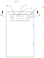
FIG. 1 is a perspective view of the present invention;
FIG. 2 is a top view of the present invention;
fig. 3 is a sectional view taken along the line a-a of fig. 2 according to the present invention;
fig. 4 is a sectional view taken along line B-B of fig. 3 according to the present invention;
FIG. 5 is an enlarged view of the present invention at C in FIG. 4;
fig. 6 is a front view of the structure of the present invention;
reference numerals: 1. an electric power box; 2. a housing; 3. a slide rail; 4. a box body; 5. a chute; 6. an L-shaped plate; 7. a telescopic rod; 71. an outer rod; 72. an inner rod; 73. connecting blocks; 74. a spring; 8. a limiting groove; 9. a screw; 10. a fan; 11. an air outlet; 12. a T-shaped rod; 13. a box door; 14. a push block; 15. a vent hole.
Detailed Description
In order to make the objects, technical solutions and advantages of the embodiments of the present invention clearer, the embodiments of the present invention will be clearly and completely described below with reference to the accompanying drawings in the embodiments of the present invention, and it is obvious that the described embodiments are some, but not all, embodiments of the present invention. The components of embodiments of the present invention, as generally described and illustrated in the figures herein, may be arranged and designed in a wide variety of different configurations.
Thus, the following detailed description of the embodiments of the present invention, presented in the accompanying drawings, is not intended to limit the scope of the invention, as claimed, but is merely representative of selected embodiments of the invention. Based on the embodiments in the present invention, all other embodiments obtained by a person skilled in the art without creative efforts belong to the protection scope of the present invention.
It should be noted that: like reference numbers and letters refer to like items in the following figures, and thus, once an item is defined in one figure, it need not be further defined and explained in subsequent figures. Furthermore, the terms "first," "second," and the like are used merely to distinguish one description from another, and are not to be construed as indicating or implying relative importance.
In the description of the embodiments of the present invention, it should be noted that the terms "inside", "outside", "up", and the like indicate the directions or positional relationships based on the directions or positional relationships shown in the drawings, or the directions or positional relationships that the products of the present invention are conventionally placed when used, and are only for convenience of describing the present invention and simplifying the description, but do not indicate or imply that the device or element to which the term refers must have a specific direction, be constructed and operated in a specific direction, and thus, should not be construed as limiting the present invention.
As shown in fig. 1, fig. 2, fig. 3, fig. 4, and fig. 6, an embodiment of the present invention provides a heat dissipation device for an electric power distribution network, which includes an electric power box 1 and a casing 2 installed inside the electric power box 1, one side of the casing 2 is an opening, two vertical sides perpendicular to the opening surface inside the casing 2 are both fixed with slide rails 3, a box body 4 capable of horizontally sliding out along the opening of the casing 2 is slidably connected between the two slide rails 3, one end of the box body 4 away from the opening is provided with a slide groove 5, the slide groove 5 is slidably connected with two L-shaped plates 6 which are symmetrical to each other, a telescopic rod 7 for pushing the two L-shaped plates 6 away from each other is connected between the two L-shaped plates 6, two vertical sides inside the casing 2 are both provided with limiting grooves 8 which are adapted to the L-shaped plates 6, both sides of the casing 2 are threaded with screws 9 corresponding to the limiting grooves 8, and, an air outlet 11 is formed in the top of the shell 2, a T-shaped rod 12 is fixed at the bottom of the shell 2, a T-shaped groove is formed in the bottom of the inner wall of the power box 1, the T-shaped rod 12 is connected in the T-shaped groove in a sliding manner, firstly, the two L-shaped plates 6 are extruded towards the mutually approaching direction by hands, at the moment, the box body 4 slides into the shell 2 through the opening of the shell 2 and along the two sliding rails 3, at the moment, the two L-shaped plates 6 are extruded from the two sides of the inner wall of the shell 2, and the extrusion force is exerted on the telescopic rod 7, when the box body 4 slides towards the shell 2 along the sliding rails 3, the two L-shaped plates 6 on the box body 4 can be driven to slide towards the shell 2, when the two L-shaped plates 6 slide to the positions of the two limiting grooves 8 on the inner wall of the shell 2, one end of the two L-shaped plates, because one end of each of the two L-shaped plates 6 slides to the position of the limiting groove 8, the two L-shaped plates 6 are not extruded by the shell 2 any more, all the two L-shaped plates 6 slide along the sliding grooves 5 and are far away from each other, so that one end of each of the two L-shaped plates 6 is inserted into the corresponding limiting groove 8, because the two ends of each of the two L-shaped plates 6 are limited by the two limiting grooves 8, the box body 4 connected with the two L-shaped plates 6 cannot slide out of the shell 2 through the sliding rails 3, so that the box body 4 and the shell 2 are fixed together, at the moment, the T-shaped rod 12 fixed at the bottom of the shell 2 slides into the power box 1 through the T-shaped groove arranged at the bottom of the inner wall of the power box 1, the installation of the heat dissipation device in the power box 1 is completed, wherein the fan 10 rotates to blow air into the shell 2, blown air enters the power box 1 through the air outlet 11 arranged at the top of the shell 2, and can dissipate heat of, when the whole device needs to be cleaned, the shell 2 can be pulled out from the power box 1 through the T-shaped groove, and then the two screw rods 9 are rotated on the two sides of the shell 2, so that the two screw rods 9 move towards the shell 2 and extrude one ends of the two L-shaped plates 6, so that the two L-shaped plates 6 are separated from the two limiting grooves 8, the box body 4 can be pulled to pull the box body 4 out of the shell 2 for cleaning, the structure in which the case 4 is mounted on the housing 2 can also be used in which the fan 10 is mounted in the case 4, the entire heat sink is easily detached from the power box 1 unlike the conventional heat sink, and the heat dissipation device can be detached to clean the inside of the heat dissipation device, so that the heat dissipation effect of the heat dissipation device cannot be influenced by excessive dust in the heat dissipation device, the safety of the power equipment in the power box 1 is enhanced, and the power equipment in the power box 1 can normally operate.
As shown in fig. 5, the structure of the telescopic rod 7 is specifically detailed, the telescopic rod 7 includes an outer rod 71 and two inner rods 72, the two inner rods 72 are movably sleeved in the outer rod 71 and located at two ends of the outer rod 71, the outer rod 71 is fixed on the box body 4, a connecting block 73 is fixed at a middle position in the outer rod 71, springs 74 are fixed at two end faces of the connecting block 73, ends of the two springs 74, which are far away from each other, are respectively and fixedly connected with one end of the corresponding inner rod 72, ends of the two inner rods 72, which are far away from each other, are respectively and fixedly connected with the corresponding L-shaped plates 6, when the inner wall of the housing 2 extrudes the two L-shaped plates 6, the two inner rods 72, which are fixedly connected with the two L-shaped plates 6, move along the outer rod 71 and approach each other, when the two inner rods 72 approach each other, the two springs 74 are extruded, wherein, when the two L-shaped plates 6 move to the position of the limiting groove 8, the buffering acting force of the two springs 74 can push the two inner rods 72 and drive the two L-shaped plates 6 to be away from each other, and one ends of the two L-shaped plates 6 are inserted into the limiting groove 8, so that the box body 4 is fixed with the shell 2.
As shown in fig. 1, in order to enhance the rationality of the whole structure, a box opening is opened on one side of the power box 1 perpendicular to the ground, and a box door 13 for shielding the box opening is hinged on the power box 1, so that the box opening of the power box 1 can be opened by pulling the box door 13 when the whole heat dissipation device is mounted and dismounted, and the mounting and dismounting of the heat dissipation device are facilitated, wherein the box opening and the opening of the housing 2 face the same direction.
As shown in fig. 1, in order to enhance the stability of the housing 2 in the power box 1, a pushing block 14 is fixed on one side of the box door 13 close to the inside of the power box 1, where the pushing block 14 is fixed on one side of the box door 13, and after the box door 13 is closed, the pushing block 14 will abut against one end of the housing 2, so that the housing 2 cannot slide in the T-shaped slot, thereby enhancing the stability of the heat dissipation device in the power box 1.
As shown in fig. 1, in consideration of the rationality of the entire structure, ventilation holes 15 are opened on both sides of the power box 1, and the air blown into the power box 1 flows out through the ventilation holes 15 by the arrangement of the ventilation holes 15.
Claims (5)
1. The heat dissipation device of the power distribution network is characterized by comprising a power box (1) and a shell (2) arranged inside the power box (1), wherein one side of the shell (2) is provided with an opening, two vertical side surfaces perpendicular to the opening surface inside the shell (2) are respectively fixed with a slide rail (3), a box body (4) capable of horizontally sliding out along the opening of the shell (2) is connected between the two slide rails (3) in a sliding manner, one end, far away from the opening, of the box body (4) is provided with a slide groove (5), the slide groove (5) is internally connected with two L-shaped plates (6) which are symmetrical to each other in a sliding manner, a telescopic rod (7) used for pushing the two L-shaped plates (6) to be away from each other is connected between the two L-shaped plates (6), two vertical side surfaces inside the shell (2) are respectively provided with a limiting groove (8) matched, the equal screw thread in both sides of casing (2) runs through have with corresponding screw rod (9) of spacing groove (8), there are fan (10) through the screw fixation in box body (4), air outlet (11) have been seted up at the top of casing (2), T type groove has been seted up to the bottom that the bottom of casing (2) is fixed with T type pole (12) and power box (1) inner wall, T type pole (12) sliding connection is at T type inslot.
2. The heat dissipation device of the power distribution network as claimed in claim 1, wherein the telescopic rod (7) comprises an outer rod (71) and two inner rods (72), the outer rod (71) is fixed on the box body (4), the two inner rods (72) are movably sleeved in the outer rod (71) and located at two ends of the outer rod (71), a connecting block (73) is fixed at a middle position in the outer rod (71), springs (74) are fixed on two end faces of the connecting block (73), one ends, far away from each other, of the springs (74) are fixedly connected with one ends of the corresponding inner rods (72), and one ends, far away from each other, of the two inner rods (72) are fixedly connected with the corresponding L-shaped plates (6).
3. The heat dissipation device for the power distribution network according to claim 1, wherein a box opening is formed in one side of the power box (1) perpendicular to the ground, and a box door (13) for shielding the box opening is hinged to the power box (1).
4. The heat dissipation device of the power distribution network according to claim 3, wherein a push block (14) is fixed on one side of the box door (13) close to the inside of the power box (1).
5. The heat dissipation device of the power distribution network according to claim 1, wherein both sides of the power box (1) are provided with ventilation holes (15).
Priority Applications (1)
| Application Number | Priority Date | Filing Date | Title |
|---|---|---|---|
| CN202022125254.XU CN212812525U (en) | 2020-09-24 | 2020-09-24 | Heat dissipation device of power distribution network |
Applications Claiming Priority (1)
| Application Number | Priority Date | Filing Date | Title |
|---|---|---|---|
| CN202022125254.XU CN212812525U (en) | 2020-09-24 | 2020-09-24 | Heat dissipation device of power distribution network |
Publications (1)
| Publication Number | Publication Date |
|---|---|
| CN212812525U true CN212812525U (en) | 2021-03-26 |
Family
ID=75089918
Family Applications (1)
| Application Number | Title | Priority Date | Filing Date |
|---|---|---|---|
| CN202022125254.XU Active CN212812525U (en) | 2020-09-24 | 2020-09-24 | Heat dissipation device of power distribution network |
Country Status (1)
| Country | Link |
|---|---|
| CN (1) | CN212812525U (en) |
-
2020
- 2020-09-24 CN CN202022125254.XU patent/CN212812525U/en active Active
Similar Documents
| Publication | Publication Date | Title |
|---|---|---|
| CN107809080A (en) | It is a kind of that there is mobile and good heat radiating function power distribution cabinet | |
| CN212812525U (en) | Heat dissipation device of power distribution network | |
| CN212969939U (en) | Intelligent information engineering network comprehensive monitoring device | |
| CN112739091B (en) | Electrical cabinet convenient to install and maintain | |
| CN109193441B (en) | Drawer type low-voltage switch cabinet | |
| CN215452208U (en) | Intelligent distribution box | |
| CN211531518U (en) | Communication box with dust removal function | |
| CN210866932U (en) | Control cabinet for electromechanical engineering | |
| CN220292356U (en) | Circuit control cabinet of building automatic control system | |
| CN113092919A (en) | Network type electric energy quality on-line monitoring device | |
| CN215772118U (en) | Concealed type intelligent distribution box with high protection level | |
| CN211791576U (en) | Industrial Internet of things communication gateway | |
| CN219937891U (en) | Comprehensive distribution box convenient for cable access | |
| CN220188938U (en) | Heat radiation structure and machine case | |
| CN216289700U (en) | Power distribution control equipment with high-stability heat dissipation mechanism | |
| CN210984467U (en) | Air-cooled dry-type transformer | |
| CN208226357U (en) | A kind of power distribution cabinet | |
| CN215117334U (en) | Computer software safety management device | |
| CN214943477U (en) | Modularization skylight link means that resets | |
| CN213976492U (en) | Simple to operate's communication line concentration case device | |
| CN211958281U (en) | Safe type block terminal convenient to installation | |
| CN220253855U (en) | Low-voltage extraction type switch cabinet based on intelligent electric power internet of things | |
| CN217823706U (en) | Low-voltage distribution board convenient to installation | |
| CN212968692U (en) | Mounting component for electric cabinet | |
| CN219879371U (en) | Combined high-low voltage electrical appliance cabinet convenient to detach |
Legal Events
| Date | Code | Title | Description |
|---|---|---|---|
| GR01 | Patent grant | ||
| GR01 | Patent grant |