CN212792461U - Copper wire take-up device - Google Patents
Copper wire take-up device Download PDFInfo
- Publication number
- CN212792461U CN212792461U CN202021411675.2U CN202021411675U CN212792461U CN 212792461 U CN212792461 U CN 212792461U CN 202021411675 U CN202021411675 U CN 202021411675U CN 212792461 U CN212792461 U CN 212792461U
- Authority
- CN
- China
- Prior art keywords
- fixedly arranged
- guide wheel
- motor
- copper wire
- guide
- Prior art date
- Legal status (The legal status is an assumption and is not a legal conclusion. Google has not performed a legal analysis and makes no representation as to the accuracy of the status listed.)
- Active
Links
Images


Abstract
The utility model discloses a copper wire take-up device in the technical field of take-up devices, which comprises a bottom plate, wherein spring columns are fixedly arranged on the left side and the right side of the top of the bottom plate, a bracket is fixedly connected with the top of the spring columns, two groups of fixed rods are fixedly arranged on the left side and the right side of the top of the bracket, a fixed plate is fixedly arranged on the top of the left side wall of the fixed rod on the left side, a motor is fixedly arranged on the top of the fixed plate, a bearing is fixedly arranged on the top of the left side wall of the fixed rod on the right side, a rotating shaft is fixedly connected with the output end of the right side wall of the motor, a wire shaft is fixedly sleeved on the outer wall of the rotating shaft, a fixed base plate is fixedly arranged on the bottom of one opposite side of the two groups of the, the utility model discloses to the copper line guide, the winding condition appears when avoiding the copper line to receive the line.
Description
Technical Field
The utility model relates to a take-up technical field specifically is a copper line take-up.
Background
At present, the copper line need receive the line operation after accomplishing wire drawing work, but traditional take-up is the reciprocating motion that the guide pulley makes a round trip, and many copper lines receive the line operation simultaneously, and the reciprocating motion of guide pulley can lead to the copper line to twine each other, and is more loaded down with trivial details, and the copper line also need guide moreover, and for this reason, we provide a copper line take-up.
SUMMERY OF THE UTILITY MODEL
An object of the utility model is to provide a copper line take-up to solve the problem that proposes in the above-mentioned background art.
In order to achieve the above object, the utility model provides a following technical scheme: a copper wire take-up device comprises a bottom plate, wherein spring columns are fixedly arranged on the left side and the right side of the top of the bottom plate, a support is fixedly connected to the top of each spring column, two groups of fixing rods are fixedly arranged on the left side and the right side of the top of the support, a fixing plate is fixedly arranged on the top of the left side wall of each fixing rod on the left side, a motor is fixedly arranged on the top of the fixing plate on the top of the left side wall of the fixing plate on the right side, a bearing is fixedly arranged on the top of the left side wall of each fixing rod on the right side, a rotating shaft is fixedly connected to the output end of the right side wall of the motor and movably assembled with the bearing, a wire shaft is fixedly sleeved on the outer wall of the rotating shaft, a fixing base plate is fixedly arranged on the bottom of, the fixed guide pulley support that is provided with of preceding lateral wall of support, the inner chamber activity of guide pulley support is equipped with the guide pulley, the spout has all been seted up to the top and the bottom of lateral wall around the assembly seat, the activity card is furnished with the slider in the spout, the lateral wall fixedly connected with limiting plate outside the spout of the orientation of slider.
Preferably, the motor is connected with an external power supply through a wire, and the motor is connected with an external controller through a wire.
Preferably, the tensioning wheels are the same size and are located on the same horizontal plane.
Preferably, the number of the guide wheels of the guide wheel bracket is two, and the guide wheels are installed in an inner cavity of the guide wheel bracket through bearings and couplers.
Preferably, the central axes of the spool, the two groups of tension wheels and the guide wheel bracket are all parallel to each other.
Compared with the prior art, the beneficial effects of the utility model are that: the utility model has the advantages of reasonable design, when receiving the line for the copper line, connect the spool with the one end of copper line, the starter motor, the motor rotates the axis of rotation, the axis of rotation relies on the bearing to rotate, the axis of rotation drives the spool rotation that the fixed cup joints on the outer wall, the spool rotates to shrink the copper line on the spool, the copper line passes through between the take-up pulley and the guide pulley, the guide pulley support guides the effect of guide pulley, the spring provides elasticity for the take-up pulley, when the copper line is being shrunk, the take-up pulley provides the tensile force for the copper line, avoid the phenomenon of twining to appear when the copper line is shrunk, and the take-up pulley assembles the inner chamber at the assembly seat, the outer wall of assembly seat has the spout, at ordinary times the take-up pulley extrudees each other, when the copper line appears swinging about relying on the, the limiting plate keeps relatively fixed, plays protection and spacing effect to the copper line, avoids the copper line to pop out from the take-up pulley within a definite time, the utility model discloses to the copper line guide, the winding condition appears when avoiding the copper line to receive the line.
Drawings
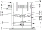
FIG. 1 is a schematic view of the overall structure of the present invention;
FIG. 2 is a side sectional view of the assembly seat of the present invention;
fig. 3 is a top view of the assembly seat of the present invention.
In the figure: 1. a base plate; 2. a spring post; 3. a support; 4. fixing the rod; 5. a fixing plate; 6. a motor; 7. a bearing; 8. a rotating shaft; 9. a bobbin; 10. fixing the substrate; 11. a spring; 12. assembling a seat; 13. a tension wheel; 14. a guide wheel bracket; 15. a guide wheel; 16. a chute; 17. a slider; 18. and a limiting plate.
Detailed Description
The technical solutions in the embodiments of the present invention will be described clearly and completely with reference to the accompanying drawings in the embodiments of the present invention, and it is obvious that the described embodiments are only some embodiments of the present invention, not all embodiments. Based on the embodiments in the present invention, all other embodiments obtained by a person skilled in the art without creative work belong to the protection scope of the present invention.
Referring to fig. 1-3, the present invention provides a technical solution: a copper wire take-up device comprises a bottom plate 1, spring columns 2 are fixedly arranged on the left side and the right side of the top of the bottom plate 1, a support 3 is fixedly connected to the top of each spring column 2, two groups of fixing rods 4 are fixedly arranged on the left side and the right side of the top of the support 3, a fixing plate 5 is fixedly arranged on the top of the left side wall of each fixing rod 4 on the left side, a motor 6 is fixedly arranged on the top of the fixing plate 5, a bearing 7 is fixedly arranged on the top of the left side wall of each fixing rod 4 on the right side, a rotating shaft 8 is fixedly connected to the output end of the right side wall of the motor 6, the rotating shaft 8 is movably assembled with the bearing 7, a spool 9 is fixedly sleeved on the outer wall of the rotating shaft 8, a fixing base plate 10 is fixedly arranged at the bottom of one side opposite to each fixing rod 4, the fixed guide pulley support 14 that is provided with of preceding lateral wall of support 3, the inner chamber activity of guide pulley support 14 is equipped with guide pulley 15, and spout 16 has all been seted up to the top and the bottom of lateral wall around assembly seat 12, and the activity card is furnished with slider 17 in the spout 16, and slider 17's the lateral wall fixedly connected with limiting plate 18 towards the spout 16 outside.
The motor 6 is connected with an external power supply through a wire, the motor 6 is connected with an external controller through a wire, the external power supply provides power for the motor 6, and the external controller can turn on and off the motor 6;
the tension pulleys 13 are the same in size and are positioned on the same horizontal plane, and the tension pulleys 13 extrude the stretched copper wires through the springs 11 to provide certain tension, so that the phenomena of direction deviation and winding of the copper wires are avoided;
the number of the guide wheels 15 of the guide wheel bracket 14 is two, the guide wheels 15 are arranged in an inner cavity of the guide wheel bracket 14 through bearings and couplers, the guide wheels 15 are guided by copper wires, and the bearings and the couplers realize the rotation of the guide wheels 15 and ensure the same rotating speed;
the central shafts of the spool 9, the two groups of tension wheels 13 and the guide wheel bracket 14 are parallel to each other, and the central shafts are parallel to each other and positioned on the same horizontal plane, so that the direction of copper wire winding cannot deviate.
The working principle is as follows: when a copper wire is taken up, one end of the copper wire is connected with a wire spool 9, a motor 6 is started, the motor 6 rotates a rotating shaft 8, the rotating shaft 8 rotates by virtue of a bearing 7, the rotating shaft 8 drives the wire spool 9 fixedly sleeved on the outer wall to rotate, the wire spool 9 rotates to shrink the copper wire on the wire spool 9, the copper wire passes through a space between tension pulleys 13 and a guide wheel 15, the guide wheel support 14 plays a role of guiding the guide wheel, a spring 11 provides elasticity for the tension pulley 13, when the copper wire is shrunk, the tension pulley 13 provides tension for the copper wire, the winding phenomenon when the copper wire is shrunk is avoided, the tension pulley 13 is assembled in an inner cavity of an assembly seat 12, a sliding groove 16 is formed in the outer wall of the assembly seat 12, the tension pulleys 13 are mutually extruded at ordinary times, when the copper wire is swung left and right when the copper wire is taken up by virtue of, and slider 17 is relative slip in spout 16, and limiting plate 18 keeps relatively fixed, plays protection and spacing effect to the copper line, avoids the copper line to pop out from take-up pulley 13 within a definite time, the utility model discloses to the copper line guide, the winding condition appears when avoiding the copper line to receive the line.
Although embodiments of the present invention have been shown and described, it will be appreciated by those skilled in the art that changes, modifications, substitutions and alterations can be made in these embodiments without departing from the principles and spirit of the invention, the scope of which is defined in the appended claims and their equivalents.
Claims (5)
1. The utility model provides a copper line take-up, includes bottom plate (1), its characterized in that: the spring column (2) is fixedly arranged on the left side and the right side of the top of the bottom plate (1), the support (3) is fixedly connected to the top of the spring column (2), two groups of fixing rods (4) are fixedly arranged on the left side and the right side of the top of the support (3), the fixing plate (5) is fixedly arranged on the top of the left side wall of the left fixing rod (4), the motor (6) is fixedly arranged on the top of the fixing plate (5), the bearing (7) is fixedly arranged on the top of the left side wall of the right side fixing rod (4), the rotating shaft (8) is fixedly connected with the output end of the right side wall of the motor (6), the rotating shaft (8) is movably assembled with the bearing (7), the bobbin (9) is fixedly sleeved on the outer wall of the rotating shaft (8), the fixing base plate (10) is fixedly arranged on the bottom of one side opposite to each of the two groups of the, the opposite ends of the springs (11) are fixedly provided with assembling seats (12), inner cavities of the assembling seats (12) are movably assembled with tensioning wheels (13), front side walls of the supports (3) are fixedly provided with guide wheel supports (14), inner cavities of the guide wheel supports (14) are movably assembled with guide wheels (15), sliding grooves (16) are formed in the tops and the bottoms of front and rear side walls of the assembling seats (12), sliding blocks (17) are movably clamped in the sliding grooves (16), and side walls of the sliding blocks (17) facing the outer sides of the sliding grooves (16) are fixedly connected with limiting plates (18).
2. The copper wire take-up device as claimed in claim 1, wherein: the motor (6) is connected with an external power supply through a wire, and the motor (6) is connected with an external controller through a wire.
3. The copper wire take-up device as claimed in claim 1, wherein: the tensioning wheels (13) are the same in size and are located on the same horizontal plane.
4. The copper wire take-up device as claimed in claim 1, wherein: the guide wheel support is characterized in that the number of the guide wheels (15) of the guide wheel support (14) is two, and the guide wheels (15) are installed in an inner cavity of the guide wheel support (14) through bearings and couplers.
5. The copper wire take-up device as claimed in claim 1, wherein: the central shafts of the bobbin (9), the two groups of tension wheels (13) and the guide wheel bracket (14) are all parallel to each other.
Priority Applications (1)
| Application Number | Priority Date | Filing Date | Title |
|---|---|---|---|
| CN202021411675.2U CN212792461U (en) | 2020-07-17 | 2020-07-17 | Copper wire take-up device |
Applications Claiming Priority (1)
| Application Number | Priority Date | Filing Date | Title |
|---|---|---|---|
| CN202021411675.2U CN212792461U (en) | 2020-07-17 | 2020-07-17 | Copper wire take-up device |
Publications (1)
| Publication Number | Publication Date |
|---|---|
| CN212792461U true CN212792461U (en) | 2021-03-26 |
Family
ID=75102981
Family Applications (1)
| Application Number | Title | Priority Date | Filing Date |
|---|---|---|---|
| CN202021411675.2U Active CN212792461U (en) | 2020-07-17 | 2020-07-17 | Copper wire take-up device |
Country Status (1)
| Country | Link |
|---|---|
| CN (1) | CN212792461U (en) |
-
2020
- 2020-07-17 CN CN202021411675.2U patent/CN212792461U/en active Active
Similar Documents
| Publication | Publication Date | Title |
|---|---|---|
| CN2837999Y (en) | Data cable strander | |
| CN111299336B (en) | Automatic wire drawing device for superconducting metal wire | |
| CN204424005U (en) | Double-deck cladding winding machine | |
| CN111703963A (en) | Wire tightening and winding device for steel strand | |
| CN213716605U (en) | High-speed cabling machine | |
| CN208607973U (en) | A kind of high-speed cable stranding-up machine | |
| CN212792461U (en) | Copper wire take-up device | |
| CN214399321U (en) | Cable winding device convenient to move and provided with anti-winding structure | |
| CN106448937B (en) | The planetary wire stranding machine of high speed | |
| CN209988857U (en) | Double-spool synchronous winding and wiring device | |
| CN218664691U (en) | Coiling mechanism is used in wire rod production | |
| CN215785771U (en) | Reciprocating type wire drawing machine is used in processing of environmental protection tin line | |
| CN211545544U (en) | Coiling mechanism for cable manufacture | |
| CN208903743U (en) | Strand winder is used in a kind of processing of wire and cable | |
| CN113257488A (en) | Back-twist structure of composite cradle type cable former | |
| CN207293781U (en) | A kind of gear-tooth bar bus cable device | |
| CN215451032U (en) | Wire distributing device of wire twisting machine for cables | |
| CN216575864U (en) | Single-line six-station cutting machine in rare earth permanent magnet industry | |
| CN215557948U (en) | Wire storage rack | |
| CN211016641U (en) | Novel special-shaped filament bundle tubular filament twister | |
| CN205194432U (en) | Shellproof silk pay -off | |
| CN219658456U (en) | Copper wire stranding machine | |
| CN203095273U (en) | Wire-feeding device of winding machine | |
| CN216014942U (en) | Stranding machine | |
| CN220232806U (en) | Wire winding mechanism of wire twisting machine |
Legal Events
| Date | Code | Title | Description |
|---|---|---|---|
| GR01 | Patent grant | ||
| GR01 | Patent grant | ||
| PE01 | Entry into force of the registration of the contract for pledge of patent right |
Denomination of utility model: A copper wire take-up device Effective date of registration: 20210929 Granted publication date: 20210326 Pledgee: Guixi Branch of Agricultural Bank of China Ltd. Pledgor: Jiangxi Yuntai Copper Co.,Ltd. Registration number: Y2021980010310 |
|
| PE01 | Entry into force of the registration of the contract for pledge of patent right |