CN212777941U - Heat exchange mechanism for air source heat pump hot water unit - Google Patents
Heat exchange mechanism for air source heat pump hot water unit Download PDFInfo
- Publication number
- CN212777941U CN212777941U CN201922176435.2U CN201922176435U CN212777941U CN 212777941 U CN212777941 U CN 212777941U CN 201922176435 U CN201922176435 U CN 201922176435U CN 212777941 U CN212777941 U CN 212777941U
- Authority
- CN
- China
- Prior art keywords
- heat exchange
- water tank
- heat
- exchange tube
- isolation cover
- Prior art date
- Legal status (The legal status is an assumption and is not a legal conclusion. Google has not performed a legal analysis and makes no representation as to the accuracy of the status listed.)
- Active
Links
Images


Abstract
The utility model discloses a heat exchange mechanism for an air source heat pump hot water unit, which comprises an isolation cover and a water tank, a mineral wool layer is embedded in the isolation cover, the pillars at the four corners of the bottom of the water tank are welded with the bottom in the isolation cover, the outer wall of the water tank is wound with a heat exchange tube, the heat exchange tube is provided with a heat radiating fin, the water tank is correspondingly provided with a heat conducting groove, the heat radiating fins are positioned in the heat conducting grooves, the water inlet of the heat exchange tube penetrates through the side wall of the isolation cover and is communicated with the outlet end of the compressor, the outlet end of the heat exchange tube penetrates through the side wall of the isolation cover to be communicated with the expansion valve, and the heat exchange tube is provided with the radiating fin, the heat conduction groove is correspondingly arranged on the water tank, the contact area between the radiating fin and the outer wall of the water tank is increased, the heat exchange efficiency is improved, the mineral wool layer is embedded in the isolation cover, the heat dissipation rate is reduced, and the heat exchange effect is further ensured.
Description
Technical Field
The utility model relates to an air source heat pump hot water unit technical field specifically is a heat transfer mechanism for air source heat pump hot water unit.
Background
The air source heat pump hot water unit is one energy saving and environment protecting hot water supply device capable of replacing boiler and producing hot water of over 50 deg.c. The air source heat pump hot water unit is suitable for places needing hot water heat sources such as indoor swimming pools, hotels, villas, hair salons, bath pedicure, factories, farms and the like. The air source heat pump hot water unit can be used for refrigerating in the heating process, and can also be installed in places which need cold quantity but have low requirements.
The heat exchange mechanism that current air source heat pump hot water unit used only twines the copper pipe on the water tank surface simply, and heat exchange efficiency is not high, and when the copper pipe heat had not transmitted completely to the water tank absorption yet simultaneously, it was not few just to have dissipated, can't guarantee the heat transfer effect.
SUMMERY OF THE UTILITY MODEL
An object of the utility model is to provide an air source heat pump heat transfer mechanism for hot water unit through installing radiating fin on the heat exchange tube, corresponds on the water tank and sets up the heat conduction groove, has increased radiating fin and water tank outer wall's area of contact, has improved heat exchange efficiency, establishes the mineral wool layer through inlaying in the cage is inside again, has reduced the heat speed of scattering and disappearing, has further guaranteed the heat transfer effect to solve the problem that proposes among the above-mentioned background art.
In order to achieve the above object, the utility model provides a following technical scheme: the utility model provides an air source heat pump heat transfer mechanism for hot water unit, includes cage and water tank, the inside mineral wool layer that is equipped with that inlays of cage, bottom welding in the pillar in water tank bottom four corners and the cage, the water tank outer wall is around being equipped with the heat exchange tube, install radiating fin on the heat exchange tube, it is provided with the heat-conducting groove to correspond on the water tank, radiating fin is located the heat-conducting groove, the heat exchange tube water inlet runs through the cage lateral wall and communicates with the compressor exit end, the heat exchange tube exit end runs through the cage lateral wall and communicates with the expansion valve.
Preferably, four corners of the bottom of the isolation cover are welded with fixing plates through support legs, and threaded holes are formed in the fixing plates.
Preferably, the top end of the threaded hole is communicated with a circular groove, and the bottom of the circular groove is glued with an elastic rubber gasket.
Preferably, the top of the water tank is communicated with a water inlet pipe, and the bottom of the water tank is communicated with a water outlet pipe.
Preferably, the heat exchange tube is a copper tube.
Preferably, the outer wall of the heat exchange tube is sleeved with a fixing sleeve, and the fixing sleeve is welded on the outer wall of the water tank.
Compared with the prior art, the beneficial effects of the utility model are that:
the water tank outer wall is provided with the heat exchange tube in a winding manner, the heat radiating fins are installed on the heat exchange tube, the heat conducting grooves are correspondingly formed in the water tank, the heat radiating fins are located in the heat conducting grooves, the contact area between the heat radiating fins and the water tank outer wall is increased, the heat exchange efficiency is improved, the mineral wool layer is embedded in the isolation cover, the heat dissipation rate is reduced, and the heat exchange effect is further guaranteed.
Drawings
Fig. 1 is a schematic structural view of the present invention;
FIG. 2 is a cross-sectional view of the water tank of the present invention;
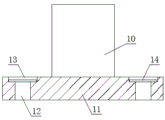
fig. 3 is a sectional view of the fixing plate of the present invention.
In the figure: 1. an isolation cover; 2. a water tank; 3. a pillar; 4. a heat exchange pipe; 5. a heat dissipating fin; 6. a heat conducting groove; 7. a layer of mineral wool; 8. a compressor; 9. an expansion valve; 10. a support leg; 11. a fixing plate; 12. a threaded hole; 13. a circular groove; 14. an elastic rubber gasket; 15. a water inlet pipe; 16. a water outlet pipe; 17. and (4) fixing sleeves.
Detailed Description
The technical solutions in the embodiments of the present invention will be described clearly and completely with reference to the accompanying drawings in the embodiments of the present invention, and it is obvious that the described embodiments are only some embodiments of the present invention, not all embodiments. Based on the embodiments in the present invention, all other embodiments obtained by a person skilled in the art without creative work belong to the protection scope of the present invention.
Referring to fig. 1-3, the present invention provides a technical solution: a heat exchange mechanism for an air source heat pump hot water unit comprises an isolation cover 1 and a water tank 2, wherein a mineral cotton layer 7 is embedded in the isolation cover 1 to reduce heat loss, four corners of the bottom of the isolation cover 1 are welded with fixing plates 11 through supporting legs 10, the fixing plates 11 are provided with threaded holes 12 which are convenient to fix, the top ends of the threaded holes 12 are communicated with a circular groove 13, the bottom of the circular groove 13 is glued with an elastic rubber gasket 14, the elastic rubber gasket 14 is arranged to enhance bolt tightening strength, supporting columns 3 at four corners of the bottom of the water tank 2 are welded with the bottom of the isolation cover 1, an inner container of the water tank 2 is made of SUS304 chrome-nickel alloy stainless steel, the top of the water tank 2 is communicated with a water inlet pipe;
the heat exchange tube 4 is wound on the outer wall of the water tank 2, the heat exchange tube 4 is a copper tube, the outer wall of the heat exchange tube 4 is sleeved with the fixing sleeve 17, the fixing sleeve 17 is welded on the outer wall of the water tank 2 to assist in fixing the heat exchange tube 4, the heat exchange tube 4 is provided with the heat dissipation fins 5, the water tank 2 is correspondingly provided with the heat conduction grooves 6, the heat dissipation fins 5 are positioned in the heat conduction grooves 6, the contact area between the heat dissipation fins 5 and the outer wall of the water tank;
the water inlet of the heat exchange tube 4 penetrates through the side wall of the isolation cover 1 and is communicated with the outlet end of the compressor 8, and the outlet end of the heat exchange tube 4 penetrates through the side wall of the isolation cover 1 and is communicated with the expansion valve 9.
The working principle is as follows: the compressor 8 compresses the backflow low-pressure refrigerant and then discharges the compressed low-pressure refrigerant into high-temperature high-pressure gas, the high-temperature high-pressure refrigerant gas flows through the heat exchange tube 4 wound outside the water tank 2, heat is conducted into the water tank 2 through the heat exchange tube 4, the cooled refrigerant becomes liquid under the continuous action of pressure and enters the evaporator of the hot water unit through the expansion valve 9, and the liquid refrigerant is rapidly evaporated into gas at the evaporator due to the fact that the pressure of the evaporator is suddenly reduced, and a large amount of heat is absorbed. Meanwhile, under the action of the fan, a large amount of air flows through the outer surface of the evaporator, energy in the air is absorbed by the evaporator, the air temperature is rapidly reduced to become cold air to be discharged outside, and then the refrigerant absorbing certain energy flows back to the compressor 8 to enter the next cycle.
Although embodiments of the present invention have been shown and described, it will be appreciated by those skilled in the art that changes, modifications, substitutions and alterations can be made in these embodiments without departing from the principles and spirit of the invention, the scope of which is defined in the appended claims and their equivalents.
Claims (6)
1. The utility model provides an air source heat pump heat transfer mechanism for hot water unit, includes cage (1) and water tank (2), its characterized in that: the utility model discloses a heat exchanger, including cage (1), isolation cover (1), bottom welding in pillar (3) and isolation cover (1) of water tank (2) bottom four corners, water tank (2) outer wall is around being equipped with heat exchange tube (4), install radiating fin (5) on heat exchange tube (4), it is provided with heat conduction groove (6) to correspond on water tank (2), radiating fin (5) are located heat conduction groove (6), heat exchange tube (4) water inlet runs through isolation cover (1) lateral wall and compressor (8) exit end intercommunication, heat exchange tube (4) exit end runs through isolation cover (1) lateral wall and expansion valve (9) intercommunication.
2. The heat exchange mechanism for the air source heat pump hot water unit as claimed in claim 1, wherein: four corners of the bottom of the isolation cover (1) are welded with fixing plates (11) through support legs (10), and threaded holes (12) are formed in the fixing plates (11).
3. The heat exchange mechanism for the air source heat pump hot water unit as claimed in claim 2, wherein: the top end of the threaded hole (12) is communicated with a circular groove (13), and the bottom of the circular groove (13) is glued with an elastic rubber gasket (14).
4. The heat exchange mechanism for the air source heat pump hot water unit as claimed in claim 1, wherein: the top of the water tank (2) is communicated with a water inlet pipe (15), and the bottom of the water tank (2) is communicated with a water outlet pipe (16).
5. The heat exchange mechanism for the air source heat pump hot water unit as claimed in claim 1, wherein: the heat exchange tube (4) is a copper tube.
6. The heat exchange mechanism for the air source heat pump hot water unit as claimed in claim 1, wherein: the outer wall of the heat exchange tube (4) is sleeved with a fixed sleeve (17), and the fixed sleeve (17) is welded on the outer wall of the water tank (2).
Priority Applications (1)
| Application Number | Priority Date | Filing Date | Title |
|---|---|---|---|
| CN201922176435.2U CN212777941U (en) | 2019-12-09 | 2019-12-09 | Heat exchange mechanism for air source heat pump hot water unit |
Applications Claiming Priority (1)
| Application Number | Priority Date | Filing Date | Title |
|---|---|---|---|
| CN201922176435.2U CN212777941U (en) | 2019-12-09 | 2019-12-09 | Heat exchange mechanism for air source heat pump hot water unit |
Publications (1)
| Publication Number | Publication Date |
|---|---|
| CN212777941U true CN212777941U (en) | 2021-03-23 |
Family
ID=75025975
Family Applications (1)
| Application Number | Title | Priority Date | Filing Date |
|---|---|---|---|
| CN201922176435.2U Active CN212777941U (en) | 2019-12-09 | 2019-12-09 | Heat exchange mechanism for air source heat pump hot water unit |
Country Status (1)
| Country | Link |
|---|---|
| CN (1) | CN212777941U (en) |
Cited By (1)
| Publication number | Priority date | Publication date | Assignee | Title |
|---|---|---|---|---|
| CN115217618A (en) * | 2021-06-24 | 2022-10-21 | 广州汽车集团股份有限公司 | Pressurized water-cooled intercooler |
-
2019
- 2019-12-09 CN CN201922176435.2U patent/CN212777941U/en active Active
Cited By (2)
| Publication number | Priority date | Publication date | Assignee | Title |
|---|---|---|---|---|
| CN115217618A (en) * | 2021-06-24 | 2022-10-21 | 广州汽车集团股份有限公司 | Pressurized water-cooled intercooler |
| CN115217618B (en) * | 2021-06-24 | 2023-11-03 | 广州汽车集团股份有限公司 | Pressurized water-cooling intercooler |
Similar Documents
| Publication | Publication Date | Title |
|---|---|---|
| CN106802020A (en) | Cold-warm circulating machine with semiconductor as refrigeration core | |
| CN102418998A (en) | Energy storage water source heat pump water heater with shower wastewater and waste heat double-absorption function | |
| CN108050607A (en) | Portable cold-hot integrated equipment | |
| CN212777941U (en) | Heat exchange mechanism for air source heat pump hot water unit | |
| JP2019100693A (en) | Movable type indoor temperature decreasing and cooling facility | |
| CN202328769U (en) | Energy accumulation type water source heat pump water heater capable of doubly absorbing waste water and waste heat of shower bath | |
| CN111588110A (en) | Portable refrigeration clothes | |
| CN211420869U (en) | Concrete heat sink is used in road and bridge construction | |
| CN211495385U (en) | Storage tank cooling device | |
| CN211146968U (en) | Spray absorber | |
| CN209672865U (en) | A kind of evaporation type oil cooler | |
| CN202119002U (en) | Water source heat pump heater capable of absorbing waste heat of shower waste water | |
| CN206739616U (en) | A kind of smart home supply equipment | |
| CN201715777U (en) | Cold-hot central storage and supply control system | |
| CN216048017U (en) | Water-saving energy-storage radiator | |
| CN110986638A (en) | Circulating water cooling energy-saving device with heat superconducting heat dissipation structure | |
| CN205536528U (en) | Energy -conserving whole room of bathing | |
| CN220119611U (en) | Microchannel condenser for circulating air source heat pump water heater | |
| CN202770052U (en) | Cool-air water heater with titanium pipe sleeved on copper pipe heat exchanger | |
| CN103335457A (en) | Superconductive condenser and evaporator of air source heat pump | |
| CN212409135U (en) | Waste heat recovery energy-saving double-source heat pump device | |
| CN210198104U (en) | Vacuum furnace thermal cycle water recycling device | |
| CN216378285U (en) | Novel heat treatment cooling thermal cycle device | |
| CN211650832U (en) | Single-layer U-shaped air condenser | |
| CN216011390U (en) | Circulating water cooling device |
Legal Events
| Date | Code | Title | Description |
|---|---|---|---|
| GR01 | Patent grant | ||
| GR01 | Patent grant |