CN212764137U - Special table-board for section carving machine - Google Patents
Special table-board for section carving machine Download PDFInfo
- Publication number
- CN212764137U CN212764137U CN202020824767.7U CN202020824767U CN212764137U CN 212764137 U CN212764137 U CN 212764137U CN 202020824767 U CN202020824767 U CN 202020824767U CN 212764137 U CN212764137 U CN 212764137U
- Authority
- CN
- China
- Prior art keywords
- carving machine
- special table
- connecting plate
- machine special
- cleaning
- Prior art date
- Legal status (The legal status is an assumption and is not a legal conclusion. Google has not performed a legal analysis and makes no representation as to the accuracy of the status listed.)
- Active
Links
Images


Abstract
The utility model relates to a special table-board for a section engraving machine, which comprises a table-board outer frame, wherein guide rails are arranged on the upper side and the lower side of the table-board outer frame, a workbench is arranged on the inner side of the guide rails, T-shaped grooves are regularly arranged on the upper part of the workbench, chip removing holes are regularly arranged in the T-shaped grooves from left to right, a dust collecting groove is arranged on the lower side of each chip removing hole, and a base is arranged on the lower side of the dust collecting; the utility model has the advantages of simple structure, wide application, clean and environmental protection, firm fixation and long service life.
Description
Technical Field
The utility model belongs to the lathe field, concretely relates to special mesa of section bar engraver.
Background
The numerical control engraving machine can be suitable for cutting on various plane materials, is widely applied to industries such as die industry, stone engraving, woodworking industry, handicraft engraving and the like, has higher and higher requirements on the numerical control engraving machine along with the development of the engraving industry, the table top of the numerical control engraving machine is an important basic accessory of the numerical control engraving machine, a placing platform is mainly provided for a workpiece to be processed, whether the workpiece is stably installed or not is related to the quality of a finished product, the normal operation of engraving is affected by accumulation of too many workpiece fragments on the working table top of the existing numerical control engraving machine, and meanwhile, a large amount of dust is caused to float in the air when a large amount of workpiece fragments are cleaned, so that the health of working personnel is seriously harmed; therefore, it is necessary to provide a table top special for a profile carving machine, which has a simple structure, wide application, cleanness, environmental protection, firm fixation and long service life.
Disclosure of Invention
The utility model aims at overcoming the defects of the prior art and providing a special table-board for a section engraving machine, which has the advantages of simple structure, wide application, cleanness, environmental protection, firm fixation and long service life.
The purpose of the utility model is realized like this: the utility model provides a special mesa of section bar engraver, it includes the mesa frame, the upper and lower both sides of mesa frame be provided with the guide rail, the inboard of guide rail be provided with the workstation, the upper portion law range of workstation have T type groove, T type groove from a left side to right law range have the chip removal hole, chip removal hole downside be provided with the dust collecting tank, the downside of dust collecting tank be provided with the base.
Further, T type inslot be provided with mounting fixture, mounting fixture include: bolts, pressure plates, screws.
Furthermore, the diameter of the chip removal hole is consistent with the width of the T-shaped groove.
Further, a cleaning assembly is arranged inside the T-shaped groove.
Further, the cleaning assembly comprises: the cleaning device comprises a handle, sliding rollers, an upper cleaning scraper, a lower cleaning scraper and a connecting plate, wherein the handle is arranged on the upper side of the connecting plate, the four sliding rollers are arranged in the middle of the connecting plate, the lower cleaning scraper is arranged at the bottom of the connecting plate, and the upper cleaning scraper is arranged on the outer side of each sliding roller.
Further, the fixing clamp can move left and right.
Further, the handle and the cleaning assembly are connected in a hinged mode.
The utility model has the advantages that: the utility model adopts the chip removal hole at the bottom of the T-shaped groove to clean the chips generated in the carving process, prevents the chips of the workpiece from influencing the next step of the carving machine, simultaneously ensures that the chips on the surface of the worktable are not piled too much, ensures the cleanness of the worktable, adopts the T-shaped groove to place the fixing bolt, ensures that the fixing bolt can flexibly move when the screw rod faces upwards, facilitates the clamping plate to clamp the workpiece, and is convenient to operate and clamp, the utility model adopts the cleaning component to clean the inside of the worktable surface and the T-shaped groove, the upper cleaning scraper can move the chips of the worktable surface and push the chips into the T-shaped groove, the lower cleaning scraper can clean the chips in the T-shaped groove, the lower scraper can send the chip image in the T-shaped groove to the chip removal hole, and avoids the carved chips of the workpiece from floating in the air when being cleaned to pollute the working environment, the body health of workers is endangered, the dust collecting groove of the utility model collects and treats the carving scraps of the workpiece, and avoids the excessive scraps from accumulating on the surface of the workbench to influence the normal operation; the utility model has the advantages of simple structure, wide application, clean environmental protection, firm fixation and long service life.
Drawings
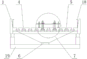
Fig. 1 is the structural schematic diagram of the special table-board for the profile carving machine of the utility model.
Fig. 2 is a front view of the special table-board for a section engraving machine of the present invention.
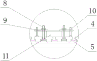
Fig. 3 is the utility model discloses a fixed subassembly schematic structure of special mesa of section bar engraver.
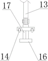
Fig. 4 is the utility model discloses a clearance subassembly schematic structure of special mesa of section bar engraver.
Figure 5 is the utility model discloses a clearance subassembly cross-sectional view of special mesa of section bar engraver.
In the figure: 1. the device comprises a guide rail 2, a table top outer frame 3, a workbench 4, a T-shaped groove 5, a chip removal hole 6, a dust collection groove 7, a fixing clamp 8, a bolt 9, a pressing plate 10, a screw 11, a processing workpiece 12, a cleaning assembly 13, a handle 14, a sliding roller 15, an upper cleaning scraper 16, a lower cleaning scraper 17, a connecting plate 18, a baffle 19 and a base.
Detailed Description
The present invention will be further described with reference to the accompanying drawings.
Example 1
As shown in fig. 1-5, a special table-board for a profile engraving machine comprises a table-board outer frame 2, guide rails 1 are arranged on the upper side and the lower side of the table-board outer frame 2, a workbench 3 is arranged on the inner side of the guide rails 1, T-shaped grooves 4 are regularly arranged on the upper portion of the workbench 3, chip removal holes 5 are regularly arranged on the T-shaped grooves 4 from left to right, a dust collection groove 6 is arranged on the lower side of each chip removal hole 5, and a base 19 is arranged on the lower side of each dust collection groove 6.
The utility model adopts the chip-removing hole 5 at the bottom of the T-shaped groove 4 to clean the chips generated in the carving process, prevents the chips of the workpiece from influencing the next working of the carving machine, simultaneously ensures that the chips on the working table surface are not accumulated too much, ensures the cleanness of the working table, adopts the T-shaped groove 4 to place the fixing bolt 8, ensures that the fixing bolt 8 can flexibly move when the screw rod faces to the upper side, facilitates the clamping plate to clamp the workpiece, flexibly operates and facilitates the clamping, adopts the cleaning component 12 to clean the table surface and the inside of the T-shaped groove 4, adopts the upper cleaning scraper 15 to move the chips of the workpiece on the surface of the cleaning working table 3, pushes the chips into the T-shaped groove 4, adopts the lower cleaning scraper 16 to clean the chips in the T-shaped groove 4, adopts the lower scraper to send the chip image in the T-shaped groove 4 to the chip-removing hole 5, avoids the carved chips of the workpiece from floating in the air when being cleaned, the dust collecting groove 6 of the utility model collects and treats the carving debris of the workpiece, thereby avoiding the excessive debris from accumulating on the surface of the worktable and influencing the normal operation; the utility model has the advantages of simple structure, wide application, clean environmental protection, firm fixation and long service life.
Example 2
As shown in fig. 1-5, a special table-board for a profile engraving machine comprises a table-board outer frame 2, guide rails 1 are arranged on the upper side and the lower side of the table-board outer frame 2, a workbench 3 is arranged on the inner side of the guide rails 1, T-shaped grooves 4 are regularly arranged on the upper portion of the workbench 3, chip removal holes 5 are regularly arranged on the T-shaped grooves 4 from left to right, a dust collection groove 6 is arranged on the lower side of each chip removal hole 5, and a base 19 is arranged on the lower side of each dust collection groove 6.
Further, T type groove 4 in be provided with mounting fixture 7, mounting fixture 7 include: the device comprises a bolt 8, a pressing plate 9 and a screw 10, wherein the fixing clamp 7 adopted by the device is simple in structure, and can firmly fix a machined workpiece 11 and avoid the machined workpiece 11 from deviating in the machining process.
Furthermore, the diameter of the chip removal hole 5 is consistent with the width of the T-shaped groove 4, and the chip removal hole 5 can better clean chips in the T-shaped groove 4 by adopting a round hole which is consistent with the width of the T-shaped groove 4.
Further, the inside of T type groove 4 be provided with clearance subassembly 12, set up clearance subassembly 12 and in time clear up workstation 3, avoid the piece to pile up.
Further, the cleaning assembly comprises: the cleaning device comprises a handle 13, sliding rollers 14, an upper cleaning scraper 15, a lower cleaning scraper 16 and a connecting plate 17, wherein the handle 13 is arranged on the upper side of the connecting plate 17, the four sliding rollers 14 are arranged in the middle of the connecting plate 17, the lower cleaning scraper 16 is arranged at the bottom of the connecting plate 17, and the upper cleaning scraper 15 is arranged on the outer side of each sliding roller.
Further, the fixing clamp 7 can move left and right, and the fixing clamp 7 can move left and right along the T-shaped groove 4.
Further, the handle 13 is connected to the cleaning assembly 12 in an articulated manner.
The utility model adopts the chip-removing hole 5 at the bottom of the T-shaped groove 4 to clean the chips generated in the carving process, prevents the chips of the workpiece from influencing the next working of the carving machine, simultaneously ensures that the chips on the working table surface are not accumulated too much, ensures the cleanness of the working table, adopts the T-shaped groove 4 to place the fixing bolt 8, ensures that the fixing bolt 8 can flexibly move when the screw rod faces to the upper side, facilitates the clamping plate to clamp the workpiece, flexibly operates and facilitates the clamping, adopts the cleaning component 12 to clean the table surface and the inside of the T-shaped groove 4, adopts the upper cleaning scraper 15 to move the chips of the workpiece on the surface of the cleaning working table 3, pushes the chips into the T-shaped groove 4, adopts the lower cleaning scraper 16 to clean the chips in the T-shaped groove 4, adopts the lower scraper to send the chip image in the T-shaped groove 4 to the chip-removing hole 5, avoids the carved chips of the workpiece from floating in the air when being cleaned, the dust collecting groove 6 of the utility model collects and treats the carving debris of the workpiece, thereby avoiding the excessive debris from accumulating on the surface of the worktable and influencing the normal operation; the utility model has the advantages of simple structure, wide application, clean environmental protection, firm fixation and long service life.
Claims (7)
1. The utility model provides a special mesa of section bar engraver, it includes the mesa frame, its characterized in that: the table top comprises a table top frame and is characterized in that guide rails are arranged on the upper side and the lower side of the table top frame, a workbench is arranged on the inner side of each guide rail, T-shaped grooves are regularly arranged on the upper portion of the workbench, chip removal holes are regularly arranged from left to right in the T-shaped grooves, a dust collection groove is arranged on the lower side of each chip removal hole, and a base is arranged on the lower side of the dust collection groove.
2. The profile carving machine special table as claimed in claim 1, characterized in that: t type inslot be provided with mounting fixture, mounting fixture include: bolts, pressure plates, screws.
3. The profile carving machine special table as claimed in claim 1, characterized in that: the diameter of the chip removal hole is consistent with the width of the T-shaped groove.
4. The profile carving machine special table as claimed in claim 1, characterized in that: the inside in T type groove be provided with the clearance subassembly.
5. The profile carving machine special table as claimed in claim 4, wherein: the cleaning assembly comprises: the cleaning device comprises a handle, sliding rollers, an upper cleaning scraper, a lower cleaning scraper and a connecting plate, wherein the handle is arranged on the upper side of the connecting plate, the four sliding rollers are arranged in the middle of the connecting plate, the lower cleaning scraper is arranged at the bottom of the connecting plate, and the upper cleaning scraper is arranged on the outer side of each sliding roller.
6. The profile carving machine special table as claimed in claim 2, characterized in that: the fixing clamp can move left and right.
7. The profile carving machine special table as claimed in claim 5, wherein: the handle is connected with the cleaning assembly in a hinged mode.
Priority Applications (1)
| Application Number | Priority Date | Filing Date | Title |
|---|---|---|---|
| CN202020824767.7U CN212764137U (en) | 2020-05-18 | 2020-05-18 | Special table-board for section carving machine |
Applications Claiming Priority (1)
| Application Number | Priority Date | Filing Date | Title |
|---|---|---|---|
| CN202020824767.7U CN212764137U (en) | 2020-05-18 | 2020-05-18 | Special table-board for section carving machine |
Publications (1)
| Publication Number | Publication Date |
|---|---|
| CN212764137U true CN212764137U (en) | 2021-03-23 |
Family
ID=75067871
Family Applications (1)
| Application Number | Title | Priority Date | Filing Date |
|---|---|---|---|
| CN202020824767.7U Active CN212764137U (en) | 2020-05-18 | 2020-05-18 | Special table-board for section carving machine |
Country Status (1)
| Country | Link |
|---|---|
| CN (1) | CN212764137U (en) |
-
2020
- 2020-05-18 CN CN202020824767.7U patent/CN212764137U/en active Active
Similar Documents
| Publication | Publication Date | Title |
|---|---|---|
| CN212764137U (en) | Special table-board for section carving machine | |
| CN210498587U (en) | Numerical control automatic band sawing machine convenient to clean sawdust | |
| CN215749719U (en) | Groove broacher | |
| CN210649498U (en) | Cutting machine tool convenient for fixing cutting object | |
| CN211566206U (en) | Automatic blowing chip removal machining spindle for furniture carving | |
| CN212794073U (en) | Numerical control machine tool convenient for fixing workpiece | |
| CN210231652U (en) | Numerical control planer-type milling machine convenient to it is clean | |
| CN212735133U (en) | Synchronous clamping mechanism capable of automatically cleaning scraps | |
| CN217122598U (en) | Double-end numerical control gantry mill | |
| CN213859680U (en) | Cutting machine for wood working | |
| CN213998729U (en) | Semi-automatic planer with dust removal function for die finishing | |
| CN219901492U (en) | Chamfering machine suitable for continuous operation | |
| CN218836375U (en) | Cutting device is used in production of accurate hardware mould | |
| CN218639185U (en) | Vertical machining center easy to clean | |
| CN214816764U (en) | Jig for auxiliary processing of special-shaped parts | |
| CN216541038U (en) | Working of plastics numerically controlled fraise machine processingequipment | |
| CN214867741U (en) | Numerical control cutting machine with dustproof function | |
| CN212977589U (en) | Auxiliary workbench for brake disc machining | |
| CN113103018B (en) | Machining center base transmission protective structure | |
| CN219665874U (en) | Cutting equipment for die machining | |
| CN219665729U (en) | Operating table of machining center | |
| CN219704331U (en) | Metal section cutting equipment | |
| CN216370355U (en) | Operating platform for machine-building mills worker | |
| CN212761549U (en) | Numerical control arc chamfering machine | |
| CN219945230U (en) | Multi-station punching and cutting machine |
Legal Events
| Date | Code | Title | Description |
|---|---|---|---|
| GR01 | Patent grant | ||
| GR01 | Patent grant |