CN212745137U - Intelligent controller with protection function - Google Patents
Intelligent controller with protection function Download PDFInfo
- Publication number
- CN212745137U CN212745137U CN202021664163.7U CN202021664163U CN212745137U CN 212745137 U CN212745137 U CN 212745137U CN 202021664163 U CN202021664163 U CN 202021664163U CN 212745137 U CN212745137 U CN 212745137U
- Authority
- CN
- China
- Prior art keywords
- motor
- installation pipe
- controller
- connecting rod
- valve core
- Prior art date
- Legal status (The legal status is an assumption and is not a legal conclusion. Google has not performed a legal analysis and makes no representation as to the accuracy of the status listed.)
- Active
Links
Images


Landscapes
- Mechanically-Actuated Valves (AREA)
Abstract
The utility model discloses an intelligent control ware with safeguard function, including the installation pipe, the inboard middle part fixed mounting of installation pipe has the sensor, and the installation pipe is inboard to be rotated and to be set up first case, the vertical fixed first connecting rod in first case top, and the installation outside of tubes is arranged in to first connecting rod free end through installation pipe lateral wall, the first worm wheel of first connecting rod free end fixed connection, and the installation intraductal side is located first case one side rotation installation second case, the vertical fixed second connecting rod in second case top along the axis direction. The beneficial effects of the utility model are that set up first case and realized dual blocking with the second case, prevented that sealed not tight from causing the fluid to leak, realized intelligent control through having set up controller, motor and sensor, when the sensor detected the interior fluid flow direction of conveying pipeline, pressure, flow exceeded preset's fusibility threshold value, the fluid in the pipeline was cut off with the second motor to the first motor of controller control, sent prompt message to the terminal simultaneously.
Description
Technical Field
The utility model belongs to the technical field of intelligent control ware, especially, relate to an intelligent control ware with safeguard function.
Background
In some large industrial fluid delivery systems, a valve is typically used as a control element for fluid delivery, and a ball valve is a valve in which a valve stem carries an opening and closing member (ball) and rotates about the axis of the valve stem. The pipeline valve in the prior art is usually required to be opened and closed by manual control, and has no pressure detection, temperature detection and leakage prevention functions, various parameters of the valve cannot be mastered in real time, remote control of the valve cannot be realized, the existing control valve has the condition of leakage which is not tight in sealing after being used for a long time, and huge loss and serious consequences can be caused if a worker cannot timely find and process the leakage, and even the life health of the worker is threatened.
SUMMERY OF THE UTILITY MODEL
The to-be-solved problem of the utility model is to provide an intelligent controller with safeguard function.
In order to solve the technical problem, the utility model discloses a technical scheme is:
an intelligent controller with a protection function comprises an installation pipe, wherein a sensor is fixedly installed in the middle of the inner side of the installation pipe, a first valve core is rotatably arranged on the inner side of the installation pipe, a first connecting rod is vertically fixed at the top of the first valve core, the free end of the first connecting rod penetrates through the side wall of the installation pipe and is arranged on the outer side of the installation pipe, the free end of the first connecting rod is fixedly connected with a first worm wheel, the inner side of the installation pipe is positioned on one side of the first valve core along the axis direction, a second valve core is rotatably installed on one side of the first valve core, a second connecting rod is vertically fixed at the top of the second valve core, the free end of the second connecting rod penetrates through the side wall of the installation pipe and is arranged on the outer side of the installation pipe, the free end of the second connecting rod is fixedly connected with a second worm wheel, a fixed, the first motor output end is fixedly connected with a first worm, the first worm is meshed with a first worm wheel, the top of the fixing frame is located on one side of the first motor, a second motor is fixedly installed on one side of the first motor, the output end of the second motor is fixedly connected with a second worm, the second worm is meshed with a second worm wheel, the installation pipe is located on a vertical installation support between the first motor and the second motor, a controller is fixedly installed on the top of the support, a sealing ring is arranged at the joint of the first valve core and the second valve core with the inner wall of the installation pipe, connecting discs are fixedly arranged at two ends of the installation pipe, through holes are uniformly formed in the connecting discs along the circumference, and the controller is electrically connected with the first motor, the second motor and the sensor.
Preferably: the controller comprises a power supply module, a processing module and a wireless communication module, wherein the processing module adopts an STM series single chip microcomputer, and the power supply module comprises an AC-DC converter and a storage battery.
So set up, be convenient for control, low cost.
Preferably: the mounting pipe is provided with a shell fixedly arranged on the periphery of the controller, the top of the shell is fixedly provided with an upper cover, and the upper cover is fixedly connected with the shell through bolts.
So set up, protect controller and motor, prevent equipment damage or cause the injury to operating personnel.
Preferably: the solar photovoltaic panel is fixedly arranged at the top of the shell and is electrically connected with the controller.
So set up, practice thrift the cost, convenient and fast, safe and reliable.
Preferably: the sensor comprises a temperature sensor and a flow velocity and flow rate sensor.
According to the arrangement, the equipment condition can be monitored more accurately.
Preferably: the sealing ring is made of rubber.
So set up, make and laminate more between sealing washer and each part, sealed effect is better.
The utility model has the advantages and positive effects that:
the utility model discloses a having set up first case and second case and having realized dual blocking, prevented that sealed not tight from causing the fluid to leak, realized intelligent control through having set up controller, motor and sensor, when the sensor detected the interior fluid flow direction of conveying pipeline, pressure, flow exceeded preset's fusibility threshold value, the fluid in the pipeline was cut off with the second motor to the first motor of controller control, sent prompt information to the terminal simultaneously.
Drawings
In order to more clearly illustrate the embodiments of the present invention or the technical solutions in the prior art, the drawings needed to be used in the description of the embodiments or the prior art will be briefly described below, it is obvious that the drawings in the following description are only some embodiments of the present invention, and for those skilled in the art, other drawings can be obtained according to these drawings without inventive exercise.
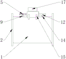
Fig. 1 is an isometric view of an intelligent controller with a protection function according to the present invention;
fig. 2 is a front view of an intelligent controller with a protection function according to the present invention; (error in label)
Fig. 3 is a front sectional view of an intelligent controller with a protection function according to the present invention; (error in label)
Fig. 4 is a top view of an intelligent controller with protection function according to the present invention;
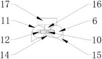
fig. 5 is a right side view of a control structure of an intelligent controller with a protection function according to the present invention;
fig. 6 is an enlarged view of a portion a of the intelligent controller with a protection function according to the present invention;
fig. 7 is a controller schematic diagram of an intelligent controller with protection function according to the present invention.
The reference numerals are explained below:
1. installing a pipe; 2. a connecting disc; 3. a housing; 4. an upper cover; 5. a first worm gear; 6. a first motor; 7. A first worm; 8. a first valve spool; 9. a first link; 10. a second worm gear; 11. a second motor; 12. a second worm; 13. a second valve core; 14. a second link; 15. a fixed mount; 16. a support; 17. a controller; 18. a seal ring; 19. a through hole; 20. a sensor.
Detailed Description
In the description of the present invention, it is to be understood that the terms "center", "longitudinal", "lateral", "up", "down", "front", "back", "left", "right", "vertical", "horizontal", "top", "bottom", "inner", "outer", and the like, indicate orientations or positional relationships based on the orientations or positional relationships shown in the drawings, and are used merely for convenience of description and for simplicity of description, and do not indicate or imply that the device or element being referred to must have a particular orientation, be constructed and operated in a particular orientation, and therefore, should not be construed as limiting the present invention. Furthermore, the terms "first", "second", etc. are used for descriptive purposes only and are not to be construed as indicating or implying relative importance or implicitly indicating the number of technical features indicated. Thus, a feature defined as "first," "second," etc. may explicitly or implicitly include one or more of that feature. In the description of the present invention, "a plurality" means two or more unless otherwise specified.
In the description of the present invention, it is to be noted that, unless otherwise explicitly specified or limited, the terms "mounted," "connected," and "connected" are to be construed broadly, and may be, for example, fixedly connected, detachably connected, or integrally connected; can be mechanically or electrically connected; they may be connected directly or indirectly through intervening media, or they may be interconnected between two elements. The specific meaning of the above terms in the present invention can be understood by those of ordinary skill in the art through specific situations.
The present invention will be further explained with reference to the accompanying drawings:
example 1
As shown in FIGS. 1-7, an intelligent controller with protection function comprises an installation tube 1, a sensor 20 is fixedly installed in the middle of the inner side of the installation tube 1, a first valve core 8 is rotatably installed in the inner side of the installation tube 1, a first connecting rod 9 is vertically fixed on the top of the first valve core 8, the free end of the first connecting rod 9 penetrates through the side wall of the installation tube 1 and is arranged on the outer side of the installation tube 1, a first worm wheel 5 is fixedly connected with the free end of the first connecting rod 9, a second valve core 13 is rotatably installed on the inner side of the installation tube 1 along the axial direction at one side of the first valve core 8, a second connecting rod 14 is vertically fixed on the top of the second valve core 13, the free end of the second connecting rod 14 penetrates through the side wall of the installation tube 1 and is arranged on the outer side of the installation tube 1, a second worm wheel 10 is fixedly connected with the free end of the second connecting rod 14, the output end of the first motor 6 is fixedly connected with the first worm 7, the first worm 7 is meshed with the first worm wheel 5, the top of the fixing frame 15 is positioned on one side of the first motor 6 to fixedly install the second motor 11, the output end of the second motor 11 is fixedly connected with the second worm 12, the second worm 12 is meshed with the second worm wheel 10, the installation pipe 1 is provided with a vertical installation support 16 between the first motor 6 and the second motor 11, the top of the support 16 is fixedly provided with a controller 17, the first valve core 8, the second valve core 13 and the inner wall of the installation pipe 1 are attached to form a sealing ring 18, two ends of the installation pipe 1 are fixedly provided with connection discs 2, the connection discs 2 are uniformly provided with through holes 19 along the circumference, and the controller 17 is electrically connected with the first motor 6, the second motor 11 and the.
The working process of the embodiment: an operator can reliably install the control device at a specified position, an instruction is input to the controller 17 through the terminal to control the opening and closing of the valve, or a specified threshold value is input to the controller 17 through the terminal, when the sensor 20 detects that the parameter in the pipeline exceeds a preset fusibility threshold value, the controller 17 controls the motor to rotate, the valve is closed, prompt information is sent to the terminal, and the double-valve arrangement can more effectively cut off the fluid medium, so that the normal operation of a conveying system of the conveying system is ensured.
Preferably: the controller 17 comprises a power supply module, a processing module and a wireless communication module, the processing module adopts an STM series single chip microcomputer, the power supply module comprises an AC-DC converter and a storage battery, the control is convenient, the cost is low, a shell 3 is fixedly arranged on the installation pipe 1 and positioned around the controller 17, an upper cover 4 is fixedly arranged on the top of the shell 3, the upper cover 4 is fixedly connected with the shell 3 through bolts to protect the controller and the motor and prevent equipment from being damaged or hurt to operators, a solar photovoltaic panel is fixedly arranged on the top of the shell 3 and is electrically connected with the controller 17, the cost is saved, the operation is convenient, rapid, safe and reliable, the sensor 20 comprises a temperature sensor 20 and a flow velocity and flow rate sensor 20, the equipment condition can be monitored more accurately, the sealing ring 18 is made of rubber, and the sealing ring is more attached to each component, the sealing effect is better.
While one embodiment of the present invention has been described in detail, the description is only a preferred embodiment of the present invention, and should not be considered as limiting the scope of the present invention. All the equivalent changes and improvements made according to the application scope of the present invention should still fall within the patent coverage of the present invention.
Claims (6)
1. The utility model provides an intelligent control ware with safeguard function, includes installation pipe (1), its characterized in that: the sensor (20) is fixedly mounted in the middle of the inner side of the installation pipe (1), the first valve core (8) is arranged on the inner side of the installation pipe (1) in a rotating mode, a first connecting rod (9) is vertically fixed to the top of the first valve core (8), the free end of the first connecting rod (9) penetrates through the side wall of the installation pipe (1) and is arranged on the outer side of the installation pipe (1), the first worm gear (5) is fixedly connected to the free end of the first connecting rod (9), the inner side of the installation pipe (1) is located on one side of the first valve core (8) along the axis direction, the second valve core (13) is rotatably mounted on one side of the first valve core (8), the second connecting rod (14) is vertically fixed to the top of the second valve core (13), the free end of the second connecting rod (14) penetrates through the side wall of the installation pipe (1) and is arranged on the outer side of the installation pipe (1), the second worm gear (10) is fixedly connected to the free end of A fixed frame (15), a first motor (6) is fixedly installed on one side of the top of the fixed frame (15), a first worm (7) is fixedly connected to the output end of the first motor (6), the first worm (7) is meshed with the first worm wheel (5), a second motor (11) is fixedly installed on one side of the first motor (6) on the top of the fixed frame (15), a second worm (12) is fixedly connected to the output end of the second motor (11), the second worm (12) is meshed with the second worm wheel (10), a vertical installation support (16) is arranged between the first motor (6) and the second motor (11) on the installation pipe (1), a controller (17) is fixedly installed on the top of the support (16), and a sealing ring (18) is arranged at the joint of the first valve core (8) and the second valve core (13) and the inner wall of the installation pipe (1), the mounting tube (1) both ends are fixed and are provided with connection pad (2), connection pad (2) evenly are provided with through-hole (19) along the circumference, controller (17) with first motor (6), second motor (11) with sensor (20) electricity is connected.
2. The intelligent controller with protection function according to claim 1, characterized in that: the controller (17) comprises a power supply module, a processing module and a wireless communication module, wherein the processing module adopts an STM series single chip microcomputer, and the power supply module comprises an AC-DC converter and a storage battery.
3. The intelligent controller with protection function according to claim 1, characterized in that: the mounting pipe (1) is located the controller (17) is fixed all around and is provided with the shell (3), the top of the shell (3) is fixed with the upper cover (4), and the upper cover (4) is fixedly connected with the shell (3) through bolts.
4. The intelligent controller with protection function according to claim 1, characterized in that: the top of the shell (3) is fixedly provided with a solar photovoltaic panel, and the solar photovoltaic panel is electrically connected with the controller (17).
5. The intelligent controller with protection function according to claim 1, characterized in that: the sensors (20) comprise a temperature sensor (20) and a flow speed and flow sensor (20).
6. The intelligent controller with protection function according to claim 1, characterized in that: the sealing ring (18) is made of rubber.
Priority Applications (1)
| Application Number | Priority Date | Filing Date | Title |
|---|---|---|---|
| CN202021664163.7U CN212745137U (en) | 2020-08-12 | 2020-08-12 | Intelligent controller with protection function |
Applications Claiming Priority (1)
| Application Number | Priority Date | Filing Date | Title |
|---|---|---|---|
| CN202021664163.7U CN212745137U (en) | 2020-08-12 | 2020-08-12 | Intelligent controller with protection function |
Publications (1)
| Publication Number | Publication Date |
|---|---|
| CN212745137U true CN212745137U (en) | 2021-03-19 |
Family
ID=74989325
Family Applications (1)
| Application Number | Title | Priority Date | Filing Date |
|---|---|---|---|
| CN202021664163.7U Active CN212745137U (en) | 2020-08-12 | 2020-08-12 | Intelligent controller with protection function |
Country Status (1)
| Country | Link |
|---|---|
| CN (1) | CN212745137U (en) |
Cited By (3)
| Publication number | Priority date | Publication date | Assignee | Title |
|---|---|---|---|---|
| CN114110214A (en) * | 2021-12-06 | 2022-03-01 | 广西电网有限责任公司钦州供电局 | Integrated valve for charging and discharging gas of power equipment |
| CN114777029A (en) * | 2022-04-18 | 2022-07-22 | 南京理工大学北方研究院 | Water supply network leakage detection device based on Internet of things |
| CN115077624A (en) * | 2022-07-28 | 2022-09-20 | 深圳市强生光电科技有限公司 | Digital temperature and humidity sensor packaging structure and use method thereof |
-
2020
- 2020-08-12 CN CN202021664163.7U patent/CN212745137U/en active Active
Cited By (4)
| Publication number | Priority date | Publication date | Assignee | Title |
|---|---|---|---|---|
| CN114110214A (en) * | 2021-12-06 | 2022-03-01 | 广西电网有限责任公司钦州供电局 | Integrated valve for charging and discharging gas of power equipment |
| CN114777029A (en) * | 2022-04-18 | 2022-07-22 | 南京理工大学北方研究院 | Water supply network leakage detection device based on Internet of things |
| CN114777029B (en) * | 2022-04-18 | 2023-11-10 | 南京理工大学北方研究院 | Water supply network leakage detection device based on Internet of things |
| CN115077624A (en) * | 2022-07-28 | 2022-09-20 | 深圳市强生光电科技有限公司 | Digital temperature and humidity sensor packaging structure and use method thereof |
Similar Documents
| Publication | Publication Date | Title |
|---|---|---|
| CN212745137U (en) | Intelligent controller with protection function | |
| CN216078541U (en) | Intelligent anti-leakage gas gate valve | |
| CN215806723U (en) | Automatic control leakage-proof valve | |
| CN214093224U (en) | Pipeline valve protection device | |
| CN211315289U (en) | Pneumatic opposite clamping type butterfly valve | |
| CN212617674U (en) | Gas conveying system with function of predicting gas leakage | |
| CN215335746U (en) | Water seal liquid level wireless monitoring device | |
| CN214198125U (en) | Lubricating system of wind driven generator main bearing | |
| CN212451200U (en) | Emergent processing apparatus that cools down of intermediate frequency furnace based on outage state | |
| CN210510407U (en) | Safety valve of polymerization inhibitor storage tank | |
| CN111963701B (en) | Remote control instrument based valve and implementation method thereof | |
| CN215861782U (en) | Valve device for gas pipeline convenient to maintain | |
| CN221004745U (en) | Fluid pipeline conveying system and activated carbon adsorption box | |
| CN218408720U (en) | Dynamic control device for main valve of isolation valve for nuclear engineering | |
| CN220248956U (en) | Butterfly valve with good sealing effect | |
| CN110701375A (en) | Butterfly valve capable of monitoring internal temperature and gas leakage | |
| CN210474925U (en) | Environment-friendly ventilation equipment for workshop | |
| CN110332324B (en) | Intelligent control's biological airtight valve | |
| CN218494326U (en) | Control valve capable of preventing mistaken collision | |
| CN212960148U (en) | Pump body valve with liquid leakage monitoring function | |
| CN212539246U (en) | A automatic instrument for oil is carried | |
| CN213776393U (en) | Two-way stop valve | |
| CN220910816U (en) | High-altitude drainage device | |
| CN213900048U (en) | Leak protection valve with automatic alarm function | |
| CN219282574U (en) | Stop valve for power station |
Legal Events
| Date | Code | Title | Description |
|---|---|---|---|
| GR01 | Patent grant | ||
| GR01 | Patent grant |