CN212743259U - Mortar spraying device for building construction capable of automatically adjusting spraying direction - Google Patents
Mortar spraying device for building construction capable of automatically adjusting spraying direction Download PDFInfo
- Publication number
- CN212743259U CN212743259U CN202020665902.8U CN202020665902U CN212743259U CN 212743259 U CN212743259 U CN 212743259U CN 202020665902 U CN202020665902 U CN 202020665902U CN 212743259 U CN212743259 U CN 212743259U
- Authority
- CN
- China
- Prior art keywords
- connecting piece
- rotating shaft
- spraying device
- discharging pipe
- mortar
- Prior art date
- Legal status (The legal status is an assumption and is not a legal conclusion. Google has not performed a legal analysis and makes no representation as to the accuracy of the status listed.)
- Expired - Fee Related
Links
Images


Abstract
The utility model discloses a can adjust mortar spraying device for construction of spraying direction by oneself, including the base, the discharging pipe and the pump body, the truckle is installed to the bottom of base, and is provided with the bottom plate between the truckle to the below of bottom plate is provided with the tight pulley, both sides all are provided with the fixture block around the connecting piece, and the fixture block is connected with the fixed plate, the bottom of inlet pipe sets up in the inside of box, and the upper right side of box has seted up the feed inlet, install the blade on the outer wall of rotary rod, and the junction of rotary rod and box is provided with the sealing washer. This can adjust mortar spraying device for construction of spraying direction by oneself, the outside laminating of discharging pipe is connected with the connecting piece, and connecting piece and reciprocal lead screw threaded connection, when reciprocal lead screw is rotatory like this, can drive connecting piece and discharging pipe and reciprocate together, makes the shower nozzle of discharging pipe left end installation carry out the change of position, can carry out spraying work on a wider scale.
Description
Technical Field
The utility model relates to a construction technical field specifically is a can adjust mortar spraying device for construction of spraying direction by oneself.
Background
The building construction refers to some work of doing in engineering construction implementation stage, and mortar spraying device is more common in the building construction, compares in traditional manual mode of paining, has not only alleviateed staff's work load, has also improved the job schedule.
However, the existing spraying device still has some disadvantages in the using process, for example, the spraying direction is not convenient to adjust, the general spraying device is only unidirectional, the positions of the general spraying device can be manually adjusted by various personnel, the spraying in different directions can be carried out, the spraying is troublesome, in the spraying process, the deposited mortar is easy to generate the phenomenon, the spraying work is influenced, and therefore the practicability of the spraying device is reduced, so that the mortar spraying device for building construction, which can automatically adjust the spraying direction, is provided, and the problems provided in the prior art are solved.
SUMMERY OF THE UTILITY MODEL
An object of the utility model is to provide a can adjust mortar spraying device for construction of spraying direction by oneself, spraying device on the existing market that the solution above-mentioned background art provided is not convenient for adjust the spraying direction, general spraying device is the folk prescription to, need the manual adjusting position of various personnel just can carry out not equidirectional spraying, it is more troublesome, and in the spraying in-process, sedimentary phenomenon appears easily in the mortar of storage, the going on of spraying work has been influenced, thereby the problem of spraying device's practicality has been reduced.
In order to achieve the above object, the utility model provides a following technical scheme: a mortar spraying device capable of automatically adjusting spraying direction for building construction comprises a base, a discharging pipe and a pump body, wherein casters are mounted at the bottom of the base, a bottom plate is arranged between the casters, a fixed wheel is arranged below the bottom plate, a first rotating shaft penetrates through the inside of the fixed wheel, the upper part of the first rotating shaft is connected with a second rotating shaft through a first transmission belt, a first conical gear is welded on the outer wall of the second rotating shaft, the rear side of the first conical gear is connected with a second conical gear in a meshed mode, a rotating rod penetrates through the inside of the second conical gear, the left side of the rotating rod is connected with a reciprocating screw rod through a second transmission belt, a connecting piece is arranged on the outer side of the reciprocating screw rod, clamping blocks are arranged on the front side and the rear side of the connecting piece and connected with a fixed plate, and the left end of the discharging pipe penetrates through the connecting piece to be, and the right-hand member of discharging pipe is connected with the pump body to the inlet pipe is installed at the top of the pump body, the bottom of inlet pipe sets up in the inside of box, and the upper right side of box has seted up the feed inlet, install the blade on the outer wall of rotary rod, and the junction of rotary rod and box is provided with the sealing washer.
Preferably, the bottom plate and the base are of an integrated structure, the bottom plate is connected with the first rotating shaft through a bearing, the first rotating shaft is connected with the fixed wheel through welding, and meanwhile the circumference of the first rotating shaft is equal to one third of the circumference of the second rotating shaft.
Preferably, the number of the fixed wheels is 2, and the lowest point of the fixed wheel and the lowest point of the caster wheel are positioned on the same straight line.
Preferably, the connection mode of the reciprocating screw rod and the connecting piece is threaded connection, and the connecting piece and the discharge pipe are in fit connection.
Preferably, the fixture block and the connecting piece are of an integrated structure, and the fixture block and the fixing plate are connected in a sliding manner.
Preferably, the connection mode of blade and rotary rod is the welding, and the connection mode of rotary rod and sealing washer is for the laminating connection to rotary rod and base are the bearing connection, have the interval between blade and the inlet pipe simultaneously.
Compared with the prior art, the beneficial effects of the utility model are that: this mortar spraying device for construction that can adjust spraying direction by oneself:
(1) the outer side of the discharging pipe is connected with a connecting piece in a fitting manner, and the connecting piece is in threaded connection with the reciprocating screw rod, so that the connecting piece can be driven to move up and down when the reciprocating screw rod rotates, the discharging pipe is driven to move up and down together, a spray head arranged at the left end of the discharging pipe can change the position, spraying work can be carried out in a wider range, and the spraying progress is improved;
(2) the fixed wheel is arranged and is welded with the first rotating shaft, the first rotating shaft is connected with the second rotating shaft through the first transmission belt, and meanwhile, the first bevel gear on the outer wall of the second rotating shaft is meshed with the second bevel gear on the outer wall of the rotating rod, so that when the fixed wheel is in contact operation with the ground, the first rotating shaft can be driven to rotate together, the second rotating shaft and the rotating rod are driven to rotate together, the blades on the outer wall of the rotating rod are rotated, mortar is stirred, the phenomenon of mortar deposition can be effectively prevented, and the normal operation of spraying work is ensured;
(3) the fixture block is arranged on the front side and the rear side of the connecting piece, the fixture block and the fixing plate are connected in a sliding mode, so that when the connecting piece drives the discharging pipe to move up and down, the discharging pipe can be more stable, the phenomenon of shaking is effectively prevented, and the stability of the device during use is further guaranteed.
Drawings
FIG. 1 is a schematic view of the overall main sectional structure of the present invention;
FIG. 2 is a schematic view of a left-side cross-sectional structure of the fixed wheel and the first rotating shaft of the present invention;
FIG. 3 is a schematic view of a top-down structure of the connection between the connecting member and the clamping block of the present invention;
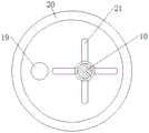
fig. 4 is the utility model discloses rotary rod and blade are connected and are cut open structure schematic diagram down.
In the figure: 1. a base; 2. a caster wheel; 3. a base plate; 4. a fixed wheel; 5. a first rotating shaft; 6. a first drive belt; 7. a second rotating shaft; 8. a first bevel gear; 9. a second bevel gear; 10. rotating the rod; 11. a second drive belt; 12. a reciprocating screw rod; 13. a connecting member; 14. a clamping block; 15. a fixing plate; 16. a discharge pipe; 17. a spray head; 18. a pump body; 19. a feed pipe; 20. a box body; 21. a blade; 22. a feed inlet; 23. and (5) sealing rings.
Detailed Description
The technical solutions in the embodiments of the present invention will be described clearly and completely with reference to the accompanying drawings in the embodiments of the present invention, and it is obvious that the described embodiments are only some embodiments of the present invention, not all embodiments. Based on the embodiments in the present invention, all other embodiments obtained by a person skilled in the art without creative work belong to the protection scope of the present invention.
Referring to fig. 1-4, the present invention provides a technical solution: a mortar spraying device capable of automatically adjusting spraying direction for building construction comprises a base 1, trundles 2, a bottom plate 3, a fixed wheel 4, a first rotating shaft 5, a first transmission belt 6, a second rotating shaft 7, a first bevel gear 8, a second bevel gear 9, a rotating rod 10, a second transmission belt 11, a reciprocating screw rod 12, a connecting piece 13, a clamping block 14, a fixed plate 15, a discharging pipe 16, a nozzle 17, a pump body 18, a feeding pipe 19, a box body 20, blades 21, a feeding port 22 and a sealing ring 23, wherein the trundles 2 are installed at the bottom of the base 1, the bottom plate 3 is arranged between the trundles 2, the fixed wheel 4 is arranged below the bottom plate 3, the first rotating shaft 5 penetrates through the fixed wheel 4, the upper part of the first rotating shaft 5 is connected with the second rotating shaft 7 through the first transmission belt 6, the first bevel gear 8 is welded on the outer wall of the second rotating shaft 7, and the rear side of the first bevel gear 8 is engaged with the second bevel gear 9, a rotating rod 10 penetrates through the second bevel gear 9, the left side of the rotating rod 10 is connected with a reciprocating screw rod 12 through a second transmission belt 11, a connecting piece 13 is arranged on the outer side of the reciprocating screw rod 12, clamping blocks 14 are arranged on the front side and the rear side of the connecting piece 13, the clamping blocks 14 are connected with a fixing plate 15, the left end of a discharge pipe 16 penetrates through the connecting piece 13 to be connected with a spray head 17, the right end of the discharge pipe 16 is connected with a pump body 18, a feed pipe 19 is arranged at the top of the pump body 18, the bottom of the feed pipe 19 is arranged inside a box body 20, a feed inlet 22 is formed in the upper right side of the box body 20, blades 21 are arranged on the outer wall of the rotating rod 10;
the bottom plate 3 and the base 1 are of an integrated structure, the bottom plate 3 is connected with the first rotating shaft 5 through a bearing, the first rotating shaft 5 is connected with the fixed wheel 4 through welding, and meanwhile, the circumference of the first rotating shaft 5 is equal to one third of the circumference of the second rotating shaft 7, so that the fixed wheel 4 can drive the first rotating shaft 5 to operate, the second rotating shaft 7 is driven to rotate rapidly, and normal use of the device is ensured;
2 fixed wheels 4 are arranged, the lowest points of the fixed wheels 4 and the caster wheels 2 are positioned on the same straight line, and when the fixed wheels 4 move and operate, the caster wheels 2 also operate, so that the use efficiency of the device is ensured;
the connection mode of the reciprocating screw rod 12 and the connecting piece 13 is threaded connection, and the connecting piece 13 and the discharge pipe 16 are in fit connection, so that when the reciprocating screw rod 12 rotates, the connecting piece 13 can be driven to move up and down, the discharge pipe 16 is driven to move up and down together, the spraying position is adjusted, and the spraying range is larger;
the clamping block 14 and the connecting piece 13 are of an integrated structure, and the clamping block 14 and the fixing plate 15 are connected in a sliding mode, so that the connecting piece 13 can move up and down more stably, and the stability of the discharging pipe 16 during movement is further ensured;
the connected mode of blade 21 and rotary rod 10 is the welding, and the connected mode of rotary rod 10 and sealing washer 23 is the laminating connection, and rotary rod 10 and base 1 are the bearing connection, have the interval between blade 21 and the inlet pipe 19 simultaneously, when rotary rod 10 is rotatory, can drive blade 21 and rotate together, stir the processing to the mortar, prevent effectively that sedimentary phenomenon from appearing in the mortar, further guarantee the normal clear of spraying work.
The working principle is as follows: when the mortar spraying device for building construction capable of automatically adjusting spraying direction is used, as shown in fig. 1-2, firstly, a worker pours mortar to be sprayed into a box body 20 from a feeding hole 22, then the pump body 18 is started, the pump body 18 sucks the mortar through a feeding pipe 19, then the mortar is sprayed out through a spray head 17 at the left end of a discharging pipe 16, meanwhile, the worker pushes the device to move, as the bottom of the base 1 is provided with the caster 2, and the lowest point of the caster 2 and the lowest point of the fixed wheel 4 are positioned on the same straight line, when the caster 2 moves, the fixed wheel 4 rotates along with the ground, so as to drive the first rotating shaft 5 to rotate together, as the upper part of the first rotating shaft 5 is connected with the second rotating shaft 7 through the first transmission belt 6, the second rotating shaft 7 can rotate together with the first conical gear 8, and further drive the second conical gear 9 and the rotating rod 10 to rotate together through the first conical gear 8, the rotating rod 10 drives the reciprocating screw rod 12 to rotate through the second transmission belt 11, and the reciprocating screw rod 12 is in threaded connection with the connecting piece 13, so that the connecting piece 13 can be driven to move up and down when the reciprocating screw rod 12 rotates, and one third of the circumference of the first rotating shaft 5 is equal to the circumference of the second rotating shaft 7, so that the second rotating shaft 7 can be driven to rotate quickly when the first rotating shaft 5 rotates, and the normal operation of the up-and-down movement of the connecting piece 13 can be ensured;
as shown in figure 3, because the interior of the connecting piece 13 is attached and connected with the discharging pipe 16, thereby driving the discharging pipe 16 to move up and down, and spraying the nozzle 17 at the left end of the discharging pipe 16 in the up-and-down direction, thereby improving the spraying efficiency, without manual adjustment by the staff, and simultaneously when the connecting piece 13 moves, the clamping blocks 14 at the front side and the rear side of the connecting piece 13 can slide along the fixing plate 15, thereby making the movement of the connecting piece 13 more stable, and ensuring the stable spraying work of the nozzle 17, as shown in figure 4, when the rotating rod 10 rotates, the blade 21 on the outer wall of the rotating rod 10 can rotate, so that the mortar inside the box body 20 can be stirred, the mortar is better sucked by the feeding pipe 19, the mortar is effectively prevented from being deposited, and the sealing ring 23 is arranged at the joint of the rotating rod 10 with the base 1 and the box body 20, thereby, the above is the operation of the whole device, and the details not described in the present specification are the prior art known to those skilled in the art.
Although the present invention has been described in detail with reference to the foregoing embodiments, it will be apparent to those skilled in the art that modifications may be made to the embodiments or portions thereof without departing from the spirit and scope of the invention.
Claims (6)
1. The utility model provides a can adjust mortar spraying device for construction of spraying direction by oneself, includes base (1), discharging pipe (16) and pump body (18), its characterized in that: the bottom of the base (1) is provided with casters (2), a base plate (3) is arranged between the casters (2), a fixed wheel (4) is arranged below the base plate (3), a first rotating shaft (5) penetrates through the fixed wheel (4), the upper portion of the first rotating shaft (5) is connected with a second rotating shaft (7) through a first transmission belt (6), the outer wall of the second rotating shaft (7) is connected with a first bevel gear (8) in a welding mode, the rear side of the first bevel gear (8) is connected with a second bevel gear (9) in a meshing mode, a rotating rod (10) penetrates through the inner portion of the second bevel gear (9), the left side of the rotating rod (10) is connected with a reciprocating screw rod (12) through a second transmission belt (11), a connecting piece (13) is arranged on the outer side of the reciprocating screw rod (12), clamping blocks (14) are arranged on the front side and the rear side of the connecting piece (13), and fixture block (14) are connected with fixed plate (15), the left end of discharging pipe (16) passes connecting piece (13) and is connected with shower nozzle (17), and the right-hand member of discharging pipe (16) is connected with the pump body (18), and inlet pipe (19) are installed at the top of the pump body (18), the bottom of inlet pipe (19) sets up in the inside of box (20), and the upper right side of box (20) has seted up feed inlet (22), install blade (21) on the outer wall of rotary rod (10), and the junction of rotary rod (10) and box (20) is provided with sealing washer (23).
2. The mortar spraying device capable of automatically adjusting the spraying direction for building construction according to claim 1, characterized in that: the base plate (3) and the base (1) are of an integrated structure, the base plate (3) and the first rotating shaft (5) are connected through bearings, the first rotating shaft (5) and the fixed wheel (4) are connected through welding, and meanwhile the circumference of the first rotating shaft (5) is equal to one third of the circumference of the second rotating shaft (7).
3. The mortar spraying device capable of automatically adjusting the spraying direction for building construction according to claim 1, characterized in that: the number of the fixed wheels (4) is 2, and the lowest point of the fixed wheels (4) and the lowest point of the caster wheels (2) are positioned on the same straight line.
4. The mortar spraying device capable of automatically adjusting the spraying direction for building construction according to claim 1, characterized in that: the reciprocating screw rod (12) is connected with the connecting piece (13) in a threaded manner, and the connecting piece (13) is connected with the discharge pipe (16) in a fitting manner.
5. The mortar spraying device capable of automatically adjusting the spraying direction for building construction according to claim 1, characterized in that: the fixture block (14) and the connecting piece (13) are of an integrated structure, and the fixture block (14) and the fixing plate (15) are connected in a sliding mode.
6. The mortar spraying device capable of automatically adjusting the spraying direction for building construction according to claim 1, characterized in that: the connection mode of blade (21) and rotary rod (10) is the welding, and the connection mode of rotary rod (10) and sealing washer (23) is for laminating the connection to rotary rod (10) and base (1) are the bearing connection, and there is the interval simultaneously between blade (21) and inlet pipe (19).
Priority Applications (1)
| Application Number | Priority Date | Filing Date | Title |
|---|---|---|---|
| CN202020665902.8U CN212743259U (en) | 2020-04-27 | 2020-04-27 | Mortar spraying device for building construction capable of automatically adjusting spraying direction |
Applications Claiming Priority (1)
| Application Number | Priority Date | Filing Date | Title |
|---|---|---|---|
| CN202020665902.8U CN212743259U (en) | 2020-04-27 | 2020-04-27 | Mortar spraying device for building construction capable of automatically adjusting spraying direction |
Publications (1)
| Publication Number | Publication Date |
|---|---|
| CN212743259U true CN212743259U (en) | 2021-03-19 |
Family
ID=75003238
Family Applications (1)
| Application Number | Title | Priority Date | Filing Date |
|---|---|---|---|
| CN202020665902.8U Expired - Fee Related CN212743259U (en) | 2020-04-27 | 2020-04-27 | Mortar spraying device for building construction capable of automatically adjusting spraying direction |
Country Status (1)
| Country | Link |
|---|---|
| CN (1) | CN212743259U (en) |
Cited By (1)
| Publication number | Priority date | Publication date | Assignee | Title |
|---|---|---|---|---|
| CN113833236A (en) * | 2021-09-01 | 2021-12-24 | 乔龙云 | Construction equipment for spraying concrete in constructional engineering |
-
2020
- 2020-04-27 CN CN202020665902.8U patent/CN212743259U/en not_active Expired - Fee Related
Cited By (1)
| Publication number | Priority date | Publication date | Assignee | Title |
|---|---|---|---|---|
| CN113833236A (en) * | 2021-09-01 | 2021-12-24 | 乔龙云 | Construction equipment for spraying concrete in constructional engineering |
Similar Documents
| Publication | Publication Date | Title |
|---|---|---|
| CN108252492A (en) | A kind of wall surface spraying devices and methods therefor of construction and decoration | |
| CN212743259U (en) | Mortar spraying device for building construction capable of automatically adjusting spraying direction | |
| CN213051184U (en) | Paint spraying equipment for hardware processing with relatively uniform paint spraying | |
| CN209935015U (en) | Trees protection against insects coating device for gardens | |
| CN213329903U (en) | Wall spraying device for building construction | |
| CN211762401U (en) | Concrete electric pole production and maintenance device capable of correcting spraying angle | |
| CN212068168U (en) | Dust device for construction | |
| CN210544665U (en) | Can effectively prevent anion for ceramic tile production mixer that dust splashes | |
| CN211612057U (en) | Building construction dust collector | |
| CN218680075U (en) | Nutrient solution spraying device for greenhouse plant cultivation | |
| CN210473410U (en) | Mist spray dust collector for building engineering | |
| CN210538381U (en) | Medicine equipment is spouted with artificial intelligence to gardens maintenance | |
| CN216367195U (en) | Water spray dust removal device for construction | |
| CN213998803U (en) | Tee bend pipe fitting inner wall processing cleaning device | |
| CN214144569U (en) | Wall spraying device for building construction | |
| CN211967964U (en) | High efficiency concrete mixing device for construction | |
| CN211707195U (en) | Automobile parts production of grease proofing lacquer subsides is with even paint spraying apparatus | |
| CN213572857U (en) | Indoor wall construction that can get unnecessary coating is with whitewashing device | |
| CN205692848U (en) | A kind of degumming spray equipment of polysilicon chip | |
| CN218306982U (en) | Civil engineering construction dust keeper | |
| CN213868801U (en) | A device of wipeing wall for decoration and fitment operation | |
| CN214942097U (en) | Coating device for building outer wall | |
| CN210787129U (en) | Blendor with automatic clearance function | |
| CN210653030U (en) | Sprinkler for car washer | |
| CN211899476U (en) | Wall painting device for architectural decoration |
Legal Events
| Date | Code | Title | Description |
|---|---|---|---|
| GR01 | Patent grant | ||
| GR01 | Patent grant | ||
| CF01 | Termination of patent right due to non-payment of annual fee |
Granted publication date: 20210319 |
|
| CF01 | Termination of patent right due to non-payment of annual fee |