CN212699472U - Medical treatment vehicle - Google Patents
Medical treatment vehicle Download PDFInfo
- Publication number
- CN212699472U CN212699472U CN202020299005.XU CN202020299005U CN212699472U CN 212699472 U CN212699472 U CN 212699472U CN 202020299005 U CN202020299005 U CN 202020299005U CN 212699472 U CN212699472 U CN 212699472U
- Authority
- CN
- China
- Prior art keywords
- upper frame
- drawer
- medical treatment
- garbage
- sliding rails
- Prior art date
- Legal status (The legal status is an assumption and is not a legal conclusion. Google has not performed a legal analysis and makes no representation as to the accuracy of the status listed.)
- Expired - Fee Related
Links
- 230000003014 reinforcing effect Effects 0.000 claims description 3
- 229940079593 drug Drugs 0.000 abstract description 7
- 239000003814 drug Substances 0.000 abstract description 7
- 238000005452 bending Methods 0.000 description 5
- 238000009434 installation Methods 0.000 description 5
- 238000003466 welding Methods 0.000 description 4
- 239000003292 glue Substances 0.000 description 2
- 239000002184 metal Substances 0.000 description 2
- 230000004048 modification Effects 0.000 description 2
- 238000012986 modification Methods 0.000 description 2
- 230000001225 therapeutic effect Effects 0.000 description 2
- 239000002906 medical waste Substances 0.000 description 1
- 230000000474 nursing effect Effects 0.000 description 1
Images
Landscapes
- Accommodation For Nursing Or Treatment Tables (AREA)
- Handcart (AREA)
Abstract
The utility model relates to a medical treatment vehicle, include: the drawer structure comprises an upper frame (1), wherein a pair of first sliding rails (103) and a pair of second sliding rails (104) are arranged inside the upper frame (1), a second drawer (7) is installed in the first sliding rails (103) in a sliding mode, and a first drawer (6) is installed in the second sliding rails (104) in a sliding mode; the upper part of the upper frame (1) is connected with an upper frame (8) covering the upper frame; the lower part of the upper frame (1) is connected with a plurality of upright posts (2), the bottoms of the upright posts (2) are connected with a lower mounting plate (3), and the bottoms of the lower mounting plate (3) are connected with a plurality of universal wheels (4); the upright post (2) is connected with a garbage can (5). The device can be used for placing various different instruments and medicines, and meanwhile, the garbage can barrel body of the device can be conveniently detached.
Description
Technical Field
The utility model relates to a medical equipment, concretely relates to medical treatment car.
Background
The treatment vehicle is one of the common devices in hospitals and is used for placing medicines and medical supplies. Wheels which are convenient to move are arranged at the bottom of the vehicle. The existing treatment vehicle is mostly of a multilayer structure, and is provided with special garbage for medical waste so as to facilitate nursing and treatment of patients, and a tray is further arranged in the barrel, so that the tray can be pulled out, and the operation area is enlarged. But when the space between two beds can only accommodate the treatment trolley to enter, the garbage can is difficult to take down and is inconvenient for daily use.
SUMMERY OF THE UTILITY MODEL
In order to solve the technical problem, the utility model aims to provide a medical treatment vehicle which can be conveniently moved in a narrow space in a hospital ward.
The technical scheme of the utility model as follows:
a medical treatment cart, comprising:
the drawer structure comprises an upper frame (1), wherein a pair of first sliding rails (103) and a pair of second sliding rails (104) are arranged inside the upper frame (1), a second drawer (7) is installed in the first sliding rails (103) in a sliding mode, and a first drawer (6) is installed in the second sliding rails (104) in a sliding mode;
the upper part of the upper frame (1) is connected with an upper frame (8) covering the upper frame;
the lower part of the upper frame (1) is connected with a plurality of upright posts (2), the bottoms of the upright posts (2) are connected with a lower mounting plate (3), and the bottoms of the lower mounting plate (3) are connected with a plurality of universal wheels (4);
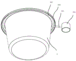
the garbage can is characterized in that a garbage can (5) is connected onto the stand column (2), the garbage can (5) specifically comprises a barrel body, a downward folded edge (501) is arranged on the upper portion of the barrel body, a cavity of a clamping block is formed by the folded edge (501) and the barrel body, a circular barrel hoop (502) is clamped into the cavity, the circular barrel hoop (502) is further connected with a linear hoop (503), a tightening ring (504) is connected to the end portion of the linear hoop (503), and the tightening ring (504) is directly connected to the stand column (2).
Furthermore, the number of the upright posts (2) is 4, and the number of the universal wheels (4) is 4.
Furthermore, a reinforcing rib (201) is connected between the upright columns (2).
Furthermore, an upper hanging part (801) is arranged on the upper frame (8).
Furthermore, a push handle (101) is arranged on the outer wall of the upper frame (1).
Borrow by above-mentioned scheme, the utility model discloses at least, have following advantage:
the device can be used for placing various different instruments and medicines, and meanwhile, the garbage can barrel body of the device can be conveniently detached.
The above description is only an overview of the technical solution of the present invention, and in order to make the technical means of the present invention clearer and can be implemented according to the content of the description, the following detailed description is made with reference to the preferred embodiments of the present invention and accompanying drawings.
Drawings
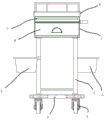
FIG. 1 is an elevational view of the present invention;
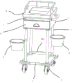
fig. 2 is a perspective view of the present invention;
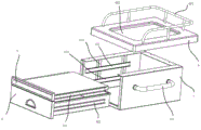
FIG. 3 is an exploded view of the upper frame and drawer of the present invention;
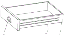
FIG. 4 is a perspective view of a first drawer of the present invention;
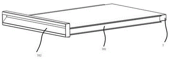
FIG. 5 is a perspective view of a second drawer of the present invention;
FIG. 6 is a perspective view of the garbage can of the present invention;
in the figure:
1-an upper frame; 101-a handle of a push handle; 102-an inner mounting plate; 103-a first slide rail; 104-a second slide rail;
2-upright post; 201-reinforcing ribs;
3-lower mounting plate;
4-universal wheels;
5-a garbage can; 501-folding edges; 502-circular cylindrical band; 503-a linear hoop; 504-tightening ring
6-a first drawer; 601-a first slider; 602-a first handle portion;
7-a second drawer; 701-a second slide block; 702-a second handle portion;
8, putting on a shelf; 801-hanging part; 802-upper hollowed out portion.
Detailed Description
The following detailed description of the embodiments of the present invention is provided with reference to the accompanying drawings and examples. The following examples are intended to illustrate the invention, but are not intended to limit the scope of the invention.
Referring to fig. 1-6, a medical treatment cart according to a preferred embodiment of the present invention is provided.
This medical treatment car specifically has included upper frame 1, and upper frame 1 is the box structure that has upper shed and a side opening that the metal was made, and upper shed and the side opening intercommunication of upper frame 1 have gone up 1 inside being equivalent to and having formed a mounting chamber.
Two inner mounting plates 102 are respectively mounted inside two side surfaces of the upper frame body 1, which are positioned at two sides of the side opening, the inner mounting plates 102 are square hollow metal tank bodies, and when the inner mounting plates 102 are specifically mounted, the inner mounting plates can be mounted inside the upper frame body 1 by welding or can be bonded and connected inside the upper frame body 1 by glue. When the installation is carried out, the inner installation plate 102 is vertically installed, the inner installation plate 102 is further connected with a first slide rail 103 and a second slide rail 104, the first slide rail 103 and the second slide rail 104 are both perpendicular to the inner installation plate 102, and the first slide rail 103 is located above the second slide rail 104.
The first drawer 6 and the second drawer 7 are installed in the upper frame 1, the first sliding blocks 601 are respectively installed on the left side and the right side of the main body of the first drawer 6, and the first drawer 6 is installed in the second sliding rail 104 through the first sliding blocks 601 during installation. The second sliders 701 are respectively installed at the left and right sides of the main body of the second drawer 7, and the second drawer 7 is installed inside the first slide rail 103 through the second sliders 701 when installed. The first drawer 6 is in a traditional drawer shape, the drawer body is in a box shape with an opening, the first handle part 602 is arranged on the outer pull surface of the first drawer 6, and the first drawer 6 can be conveniently pulled and pulled to be opened through the first handle part 602. The cylindrical surface of the second drawer 7 is a plate mechanism without any storage space therein, and a second handle portion 702 is provided on the coming surface of the second drawer 7. In particular arrangements, the first handle portion 602 is formed as a semi-circular depression and the second handle portion 702 is formed as an elongated depression.
An upper frame 8 is further connected to the upper portion of the upper frame 1, the upper frame 8 is in a cover shape, a square upper hollow portion 802 is arranged in the specific middle of the upper frame, the shape of the upper frame 8 is slightly larger than that of the upper frame 1, therefore, the upper frame 8 can be sleeved on the upper portion of the upper frame 1, an upper hanging portion 801 is further arranged on the upper portion of the upper frame 8, the upper hanging portion 801 is a pipe mounted on the upper frame 8, two ends of the pipe are connected with the upper frame 8, the pipe is formed into an upward bending portion through two welded ends, a multi-section connected bending portion is formed at the end portion of the bending portion, the distances from the bending portion to the surface of the upper frame 8 are consistent, and meanwhile, a support rod is generally connected below the bending portion.
A handle 101 is welded to the outside of one side surface of the upper frame 1.
Four corners of the lower part of the upper frame 1 are connected with four upright posts 2, and the four upright posts are connected by welding when in specific connection.
The four columns 2 are all connected to the lower mounting plate 3 at the bottom, and are also connected by welding when in specific connection.
A universal wheel 4 is connected to four corners of the bottom of the lower mounting plate 3, and the universal wheel 4 is a universal wheel commonly used in the prior art, and the top of the universal wheel is inserted into a mounting hole connected to the lower part of the lower mounting plate 3.
The garbage can 5 is further connected to the side face of the upright post 2, the garbage can 5 specifically comprises a barrel, a downward folded edge 501 is arranged on the upper portion of the barrel, a clamping cavity is formed by the folded edge 501 and the barrel, the clamping cavity is used for clamping a circular barrel hoop 502, the circular barrel hoop 502 is further connected with a linear hoop 503, and the end of the linear hoop 503 is connected with a tightening ring 504. The tightening ring 504 is directly connected to the upright post 2, and can be adhered by glue during specific connection, so as to maintain stability. To facilitate the snap-fit of the linear clamp 503 into the hem, a mounting opening is also provided in the hem.
The working principle of the utility model is as follows:
the barrel of the garbage can 5 can be conveniently taken down from the circular barrel hoop, and meanwhile can be conveniently installed and returned, so that the treatment vehicle can conveniently run in a narrow space. The garbage can 5 is made of plastic.
A plurality of therapeutic devices and medicines can be placed in the first drawer 6, and a plurality of therapeutic devices and medicines can be placed on the second drawer 7.
The upper part of the upper frame 8 can be externally hung with different instruments and medicines.
The treatment trolley can be conveniently moved by matching the push handle with the universal wheels.
The reinforcing ribs 201 are connected between the upright columns 2 to maintain stability, and welding is adopted during specific connection.
The device has the following advantages:
the device can be used for placing various different instruments and medicines, and meanwhile, the garbage can barrel body of the device can be conveniently detached.
The above description is only a preferred embodiment of the present invention, and is not intended to limit the present invention, and it should be noted that, for those skilled in the art, a plurality of modifications and variations can be made without departing from the technical principle of the present invention, and these modifications and variations should also be regarded as the protection scope of the present invention.
Claims (5)
1. A medical treatment cart, comprising:
the drawer structure comprises an upper frame (1), wherein a pair of first sliding rails (103) and a pair of second sliding rails (104) are arranged inside the upper frame (1), a second drawer (7) is installed in the first sliding rails (103) in a sliding mode, and a first drawer (6) is installed in the second sliding rails (104) in a sliding mode;
the upper part of the upper frame (1) is connected with an upper frame (8) covering the upper frame;
the lower part of the upper frame (1) is connected with a plurality of upright posts (2), the bottoms of the upright posts (2) are connected with a lower mounting plate (3), and the bottoms of the lower mounting plate (3) are connected with a plurality of universal wheels (4);
the garbage can is characterized in that a garbage can (5) is connected onto the stand column (2), the garbage can (5) specifically comprises a barrel body, a downward folded edge (501) is arranged on the upper portion of the barrel body, a cavity of a clamping block is formed by the folded edge (501) and the barrel body, a circular barrel hoop (502) is clamped into the cavity, the circular barrel hoop (502) is further connected with a linear hoop (503), a tightening ring (504) is connected to the end portion of the linear hoop (503), and the tightening ring (504) is directly connected to the stand column (2).
2. The medical treatment cart of claim 1, wherein: the number of the upright posts (2) is 4, and the number of the universal wheels (4) is 4.
3. The medical treatment cart of claim 2, wherein: and reinforcing ribs (201) are connected between the upright columns (2).
4. The medical treatment cart of claim 1, wherein: an upper hanging part (801) is arranged on the upper frame (8).
5. The medical treatment cart of claim 1, wherein: and a push handle (101) is arranged on the outer wall of the upper frame (1).
Priority Applications (1)
| Application Number | Priority Date | Filing Date | Title |
|---|---|---|---|
| CN202020299005.XU CN212699472U (en) | 2020-03-12 | 2020-03-12 | Medical treatment vehicle |
Applications Claiming Priority (1)
| Application Number | Priority Date | Filing Date | Title |
|---|---|---|---|
| CN202020299005.XU CN212699472U (en) | 2020-03-12 | 2020-03-12 | Medical treatment vehicle |
Publications (1)
| Publication Number | Publication Date |
|---|---|
| CN212699472U true CN212699472U (en) | 2021-03-16 |
Family
ID=74905734
Family Applications (1)
| Application Number | Title | Priority Date | Filing Date |
|---|---|---|---|
| CN202020299005.XU Expired - Fee Related CN212699472U (en) | 2020-03-12 | 2020-03-12 | Medical treatment vehicle |
Country Status (1)
| Country | Link |
|---|---|
| CN (1) | CN212699472U (en) |
-
2020
- 2020-03-12 CN CN202020299005.XU patent/CN212699472U/en not_active Expired - Fee Related
Similar Documents
| Publication | Publication Date | Title |
|---|---|---|
| CN202314112U (en) | Multi-purpose rescue cart for hospital clinical treatment | |
| CN212699472U (en) | Medical treatment vehicle | |
| CN111374853A (en) | Medical treatment vehicle | |
| CN201814745U (en) | Medical flat car | |
| CN108158761A (en) | A kind of multifunctional medical cart | |
| CN212140999U (en) | Shelf structure on sterilization vehicle | |
| CN210933237U (en) | Multifunctional internal medicine clinical breathing device | |
| CN210542252U (en) | Novel treatment vehicle | |
| CN209316059U (en) | A kind of Medical multifunctional trolley | |
| CN216455825U (en) | Case shallow that facilitates use | |
| CN215398775U (en) | Disinfection apparatus transport vechicle | |
| CN214415134U (en) | Nursing handcart | |
| CN211327212U (en) | Neurosurgery drainage is with nursing frame | |
| CN212347050U (en) | Liftable treatment car | |
| CN213406764U (en) | Treatment vehicle | |
| CN110934709A (en) | Movable puncture platform for pediatrics | |
| CN217186829U (en) | Multifunctional tailstock vehicle and medical sickbed | |
| CN213941328U (en) | Device is put to critical patient treatment car standard article | |
| CN210056584U (en) | Nurse is with multi-functional nursing case | |
| CN212118514U (en) | Emergency medical nursing trolley for emergency room | |
| CN215535010U (en) | Operation position apparatus placing vehicle | |
| CN219743195U (en) | Nursing support | |
| CN213406765U (en) | Medical record clamping vehicle | |
| CN211592632U (en) | Handcart that shock attenuation effect is excellent | |
| CN212118447U (en) | Department of anesthesia uses first-aid kit |
Legal Events
| Date | Code | Title | Description |
|---|---|---|---|
| GR01 | Patent grant | ||
| GR01 | Patent grant | ||
| CF01 | Termination of patent right due to non-payment of annual fee |
Granted publication date: 20210316 |
|
| CF01 | Termination of patent right due to non-payment of annual fee |