CN212671286U - Strutting arrangement for ancient building restoration - Google Patents
Strutting arrangement for ancient building restoration Download PDFInfo
- Publication number
- CN212671286U CN212671286U CN202020939734.7U CN202020939734U CN212671286U CN 212671286 U CN212671286 U CN 212671286U CN 202020939734 U CN202020939734 U CN 202020939734U CN 212671286 U CN212671286 U CN 212671286U
- Authority
- CN
- China
- Prior art keywords
- fixed
- supporting
- stay tube
- rotating
- supporting seat
- Prior art date
- Legal status (The legal status is an assumption and is not a legal conclusion. Google has not performed a legal analysis and makes no representation as to the accuracy of the status listed.)
- Expired - Fee Related
Links
Images

Abstract
The utility model relates to a strutting arrangement for ancient architecture restoration, including the supporting seat, sliding connection has the stay tube in the supporting seat, and the vertical setting of stay tube is fixed with actuating mechanism in the supporting seat, and actuating mechanism links to each other with the stay tube, and the top of stay tube is rotated and is connected with supporting mechanism, and supporting mechanism rotates including rotating the piece and articulated fixed support piece on rotating the lateral wall, rotates the cover and establishes to be connected with the stay tube rotation on the stay tube. The utility model discloses have the ancient building of the different angles of adaptable different grade type and then realize the effect of firm support.
Description
Technical Field
The utility model belongs to the technical field of the technique of supporting equipment and specifically relates to a strutting arrangement is used in ancient building restoration.
Background
Ancient buildings are easy to damage the foundation, the platform foundation, the terrace, the wall body, the wooden framework, the roof tile, the wooden base layer, the painted ground layer and other parts, the foundation is easy to subside and break, the platform foundation is easy to loosen and shift the step edge stones, the wall body is cracked and inclined, the wooden framework is easy to crack, break, sag, decay and other damages, and the damages are easy to collapse due to the loss of repair over the years. In the repair process, need carry out firm support to its different positions, consequently when renovating, renovating the ancient building, need utilize the support frame to support the ancient building.
The structure of the existing support frame is fixed, the support frame cannot adapt to the support requirements of various types of ancient buildings, and the working efficiency is reduced.
SUMMERY OF THE UTILITY MODEL
The utility model aims at providing a strutting arrangement for ancient building restoration, its ancient building that has the different angles of adaptable different grade type and then realizes the effect of firm support.
The above utility model discloses an above-mentioned utility model purpose can realize through following technical scheme:
supporting device for ancient architecture restoration, including the supporting seat, sliding connection has the stay tube in the supporting seat, and the vertical setting of stay tube is fixed with actuating mechanism in the supporting seat, and actuating mechanism links to each other with the stay tube, and the top of stay tube is rotated and is connected with supporting mechanism, and supporting mechanism is including rotating the piece and rotating the articulated fixed support piece on a lateral wall, rotates a cover and establishes to be connected with the stay tube rotation on the stay tube.
Through adopting above-mentioned technical scheme, through the cooperation setting of actuating mechanism with the support column to be convenient for adjust the ancient building of the height of support column in order to adapt to co-altitude not, through rotating the cooperation setting with support piece, be convenient for adjust support piece's angle, further stabilize the support to the ancient building of difference.
The utility model discloses further set up to: the rotating part comprises a rotating sleeve and a rotating ring, and the rotating ring is fixedly connected with the bottom end of the rotating sleeve. The rotating sleeve is rotatably connected with the supporting tube, a plurality of fixing holes are formed in the supporting tube at positions opposite to the rotating ring and at equal intervals along the circumferential direction of the supporting column, a locking piece is fixed on the rotating ring, and the locking piece is clamped into the fixing holes.
Through adopting above-mentioned technical scheme, through the cooperation setting of rotating cover and rotating ring, rotate the cover and drive to rotate and encircle the support column and rotate, go into the fixed orifices through retaining member card, realize rotating the piece and fix with the stay tube.
The utility model discloses further set up to: the retaining member includes fixed chamber, fixed chamber lateral wall passes through bolt fixed connection with the rotating ring lateral wall, it is provided with the joint post to run through fixed chamber, set up the perforation that supplies the joint post to stretch out on the lateral wall of rotating ring is kept away from to fixed chamber length direction, the joint post sets up along the length direction in fixed chamber, joint post wherein one end stretches to the stay tube, the part cover that sets up in fixed intracavity portion at the joint post is equipped with the spring, the spring is close to the one end fixedly connected with joint piece of stay tube, the width of joint piece is greater than fenestrate diameter.
Through adopting above-mentioned technical scheme, through the setting of retaining member, the joint post stretches into corresponding fixed orifices under free state, and it is fixed to rotate cover and rotating ring. Later pulling joint post, joint piece compression spring simultaneously to pull out the joint post from the fixed orifices, and then adjust as required and rotate the cover and fix the support piece's on rotating the cover angle.
The utility model discloses further set up to: the support piece comprises a supporting plate and an adjusting rod, one end of the supporting plate in the length direction is hinged and fixed with the rotating sleeve, the lower surface of one end, away from the supporting tube, of the supporting plate is hinged and fixed with one end of the adjusting rod, the other end of the adjusting rod is located below the supporting plate and hinged and fixed with the side wall of the rotating ring, and the adjusting rod is a telescopic rod.
Through adopting above-mentioned technical scheme, through the cooperation setting of adjusting pole and backup pad, adjust the length of regulating lever to be convenient for adjust the inclination of backup pad as required.
The utility model discloses further set up to: the adjusting rod comprises a threaded column and an adjusting pipe, reverse threaded sections are respectively arranged at two ends of the threaded column, and two ends of the threaded column are respectively in threaded connection with the corresponding adjusting pipes.
Through adopting above-mentioned technical scheme, through the setting of adjusting the pole, the screw thread post links to each other with the control tube to twist and move the screw thread post, make the length of adjusting the pole realize adjusting.
The utility model discloses further set up to: a fixing ring is fixed at the midpoint position of the threaded column in the length direction.
Through adopting above-mentioned technical scheme, through the setting of solid fixed ring, be convenient for twist and move the screw thread post.
The utility model discloses further set up to: the driving mechanism comprises a rotating rod and a first bevel gear positioned in the supporting seat, the bottom end of the rotating rod penetrates through an inner hole of the first bevel gear, is fixedly connected with the first bevel gear and is rotatably connected with the supporting seat, the top end of the rotating rod penetrates through the supporting seat, is meshed with the first bevel gear, penetrates through an inner hole of a second bevel gear and is fixedly connected with a rotating shaft, and the end, far away from the supporting seat, of the rotating shaft is fixedly connected with a motor.
By adopting the technical scheme, the small-sized motor is started through the arrangement of the driving mechanism, so that the rotating shaft drives the second bevel gear to rotate, and further the first bevel gear meshed with the second bevel gear drives the rotating rod to rotate.
The utility model discloses further set up to: the supporting tube is in threaded connection with the rotating rod, a limiting part is fixed on the upper surface of the supporting seat, and the limiting part is in sliding connection with the supporting tube.
Through adopting above-mentioned technical scheme, through the setting of locating part, prevent that the stay tube from rotating along with the dwang.
The utility model discloses further set up to: the locating part includes the spacing ring, and the spacing ring cover is established on the stay tube, and the both sides at the spacing ring are relatively fixed with the dead lever respectively, and the top and the spacing ring lateral wall of dead lever are fixed, and the bottom and the supporting seat upper surface of dead lever are fixed, have seted up the spacing groove at the stay tube lateral wall, and the length direction of spacing groove is unanimous with the length direction of stay tube, is fixed with the lug respectively in the relative position of spacing ring inside wall and spacing groove, and the lug card is in the spacing groove.
Through adopting above-mentioned technical scheme, through the cooperation setting of spacing groove and lug, restriction and dwang threaded connection's stay tube reciprocates along the dwang length direction.
To sum up, the utility model discloses a beneficial technological effect does:
1. the driving mechanism is matched with the supporting columns, the small-sized motor is started, the rotating shaft drives the second bevel gear to rotate, the first bevel gear meshed with the second bevel gear drives the rotating rod to rotate, and the limiting piece is matched with the driving mechanism, so that the height of the supporting columns can be conveniently adjusted to adapt to ancient buildings with different heights;
2. through the cooperation setting of rotating piece and support piece, be convenient for adjust support piece's angle, further stabilize the support to the ancient building of difference.
Drawings
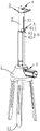
FIG. 1 is a schematic structural view of a support device for repairing ancient buildings;
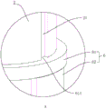
FIG. 2 is a cross-sectional view of the support mechanism;
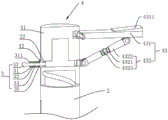
FIG. 3 is a schematic view of the drive mechanism;
fig. 4 is a partially enlarged schematic view of a portion a in fig. 1.
In the figure, 1, a support seat; 11. a support leg; 2. supporting a tube; 21. a limiting groove; 22. a fixing hole; 3. a locking member; 31. a fixed cavity; 311. perforating; 32. a clamping column; 33. a fixed block; 34. a spring; 35. a clip sheet; 4. a support mechanism; 41. rotating the sleeve; 42. a rotating ring; 43. a support member; 431. a support plate; 4311. a butting block; 432. adjusting a rod; 4321. a threaded post; 4322. an adjusting tube; 4323. a fixing ring; 5. a drive mechanism; 51. rotating the rod; 52. a first bevel gear; 53. a second bevel gear; 54. a rotating shaft; 55. a motor; 6. a limiting member; 61. a limiting ring; 611. a bump; 62. and (5) fixing the rod.
Detailed Description
The present invention will be described in further detail with reference to the accompanying drawings.
Referring to fig. 1, for the utility model discloses a strutting arrangement for ancient building restoration, including supporting seat 1, fixed surface has three stabilizer blade 11 under supporting seat 1, and stabilizer blade 11 encloses and establishes into a triangle-shaped to the realization is to the firm support of supporting seat 1. A supporting tube 2 is connected in the supporting seat 1 in a sliding way, and the supporting tube 2 is arranged vertically. A driving mechanism 5 is fixed in the supporting seat 1, the driving mechanism 5 is rotatably connected with the supporting tube 2, and the supporting tube 2 is driven by the driving mechanism 5 to move up and down along the vertical direction. The supporting mechanism 4 is rotatably connected to the top end of the supporting pipe 2, and the supporting mechanism 4 can rotate around the supporting pipe 2, so that stable support at different angles can be realized according to different buildings.
Referring to fig. 2, the support mechanism 4 includes a rotating sleeve 41 and a rotating ring 42, and a support 43 is hingedly fixed to a side wall of the rotating sleeve 41. The rotating ring 42 is fixedly connected with the bottom end of the rotating sleeve 41. The rotating sleeve 41 is rotatably connected with the support tube 2, the rotating ring 42 rotates along with the rotation of the rotating tube, and the rotating sleeve 41 and the support tube 2 are quickly fixed through the locking piece 3.
A plurality of fixing holes 22 are formed in the support tube 2 at positions opposite to the rotating ring 42 and at equal intervals along the circumferential direction of the support column, and the locking piece 3 is fixed on the rotating ring 42. The locking element 3 can be snapped into the fastening opening 22 in order to fasten the rotary sleeve 41 to the support tube 2. The locking member 3 comprises a fixing cavity 31, the side wall of the fixing cavity 31 is fixedly connected with the side wall of the rotating ring 42 through a bolt, and the fixing cavity 31 is a rectangular cavity with a hollow interior. Run through fixed chamber 31 and be provided with joint post 32, offer the perforation 311 that supplies joint post 32 to stretch out on the lateral wall of fixed chamber 31 length direction keeping away from swivel 42, joint post 32 sets up along the length direction of fixed chamber 31, and joint post 32 wherein one end stretches to stay tube 2, and the other end of joint post 32 passes perforation 311 fixedly connected with fixed block 33. The spring 34 is sleeved on the part, arranged inside the fixing cavity 31, of the clamping column 32, the length direction of the spring 34 is arranged along the length direction of the fixing cavity 31, the clamping sheet 35 is fixedly connected to one end, close to the support tube 2, of the spring 34, and the width of the clamping sheet 35 is larger than that of the through hole 311.
In the free state, the engagement posts 32 extend into the corresponding fixing holes 22, and fix the rotary sleeve 41 and the rotary ring 42. Then, the latch post 32 is pulled, and the latch piece 35 compresses the spring 34, so that the latch post 32 is pulled out from the fixing hole 22, and the angles of the rotating sleeve 41 and the supporting piece 43 fixed on the rotating sleeve 41 are adjusted as required. When the fixing block 33 is released, the spring 34 drives the fastening column 32 to move toward the supporting tube 2, and then returns to the position where the fastening column 32 extends into the corresponding fixing hole 22, so as to fix the supporting column with the rotating sleeve 41 and the rotating ring 42.
The support member 43 includes a support plate 431 and an adjustment lever 432, one end of the support plate 431 in the length direction is hinged to the rotating sleeve 41, and the lower surface of the other end of the support plate 431 is hinged to one end of the adjustment lever 432. The other end of the adjusting rod 432 is located below the supporting plate 431 and is hinged and fixed with the side wall of the rotating ring 42. The adjusting rod 432 comprises a threaded column 4321 and an adjusting tube 4322, wherein reverse threaded sections are respectively formed at two ends of the threaded column 4321, two ends of the threaded column 4321 are respectively in threaded connection with the corresponding adjusting tube 4322, a fixing ring 4323 is fixed at the midpoint position of the threaded column 4321 in the length direction, and the threaded column 4321 is conveniently screwed through the fixing ring 4323, so that the length of the adjusting rod 432 is adjusted. Through the change of adjusting pole 432 length, and then drive and adjust the slope difference of pole 432 articulated fixed backup pad 431, be convenient for adapt to the ancient building of different shapes and stabilize the support.
An abutting block 4311 is fixed on the upper surface of one end, far away from the rotating sleeve 41, of the supporting plate 431, and the upper surface of the abutting block 4311 is obliquely arranged, so that the ancient building can be further stably supported.
Referring to fig. 1 and 3, the driving mechanism 5 includes a rotating rod 51 and a first bevel gear 52 located in the support seat 1, the diameter of the rotating rod 51 is the same as the diameter of the inner hole of the first bevel gear 52, the bottom end of the rotating rod 51 passes through the inner hole of the first bevel gear 52 to be fixedly connected with the first bevel gear 52 and rotatably connected with the support seat 1, and the top end of the rotating rod 51 penetrates through the support seat 1 to be vertically arranged. A second bevel gear 53 is meshed with the first bevel gear 52, a rotating shaft 54 is arranged through the inner hole of the second bevel gear 53, the rotating shaft 54 is fixedly connected with the second bevel gear 53, and a motor 55 is fixedly connected at one end of the rotating shaft 54 far away from the supporting seat 1. The portion of the rotating rod 51 located outside the support seat 1 is screwed with the support pipe 2.
Referring to fig. 1 and 4, a stopper 6 is fixed to an upper surface of the support base 1 so as to facilitate the rotation of the support pipe 2 with the rotation lever 51. The limiting part 6 comprises a limiting ring 61, the limiting ring 61 is sleeved on the support tube 2, fixing rods 62 are respectively and oppositely fixed on two sides of the limiting ring 61, the top end of each fixing rod 62 is fixed with the side wall of the limiting ring 61, and the bottom end of each fixing rod 62 is fixed with the upper surface of the support seat 1. The outer side wall of the support tube 2 is provided with a limit groove 21, and the length direction of the limit groove 21 is consistent with that of the support tube 2. The inner side wall of the limiting ring 61 is fixed with a projection 611 at a position opposite to the limiting groove 21, and the projection 611 is clamped in the limiting groove 21, so that the support pipe 2 is prevented from rotating the rotary rod 51.
By starting the motor 55, the rotating shaft 54 drives the second bevel gear 53 to rotate, and the first bevel gear 52 engaged with the second bevel gear 53 drives the rotating rod 51 to rotate, the projection 611 of the matching limiting ring 61 is clamped in the limiting groove 21 of the supporting tube 2, and the supporting tube 2 screwed with the rotating rod 51 moves up and down along the length direction of the rotating rod 51 by the rotation of the rotating rod 51. Therefore, the device can adapt to ancient buildings to be repaired with different heights and realize stable support. Through rotating the cover 41 and fixing the setting of support piece 43 on rotating the cover 41, rotate the cover 41 and adjust to required position to it is fixed with the stay tube 2 to rotate the cover 41 through retaining member 3, adjust the length of pole 432, make the different angles that can incline of backup pad 431, and then realize the firm support to different ancient buildings.
The embodiment of this specific implementation mode is the preferred embodiment of the present invention, not limit according to this the utility model discloses a protection scope, so: all equivalent changes made according to the structure, shape and principle of the utility model are covered within the protection scope of the utility model.
Claims (9)
1. Strutting arrangement for ancient building restoration, including supporting seat (1), its characterized in that: supporting seat (1) sliding connection has stay tube (2), and stay tube (2) vertical setting is fixed with actuating mechanism (5) in supporting seat (1), and actuating mechanism (5) link to each other with stay tube (2), and the top of stay tube (2) is rotated and is connected with supporting mechanism (4), and supporting mechanism (4) are including rotating the piece and articulated fixed support piece (43) on rotating the lateral wall, rotate the piece cover and establish and rotate with stay tube (2) on stay tube (2) and be connected.
2. The supporting device for repairing ancient buildings according to claim 1, wherein: the rotation piece is including rotating cover (41) and rotating ring (42), and rotating ring (42) and the bottom fixed connection who rotates cover (41) rotate cover (41) and be connected with stay tube (2) rotation, and stay tube (2) are gone up and are offered a plurality of fixed orificess (22) with rotating ring (42) relative position and along support column circumference equidistance, are fixed with retaining member (3) on rotating ring (42), and retaining member (3) card is gone into fixed orificess (22).
3. The supporting device for repairing ancient buildings according to claim 2, wherein: retaining member (3) are including fixed chamber (31), fixed chamber (31) lateral wall passes through bolt fixed connection with swivel becket (42) lateral wall, it is provided with joint post (32) to run through fixed chamber (31), set up on the lateral wall of keeping away from swivel becket (42) at fixed chamber (31) length direction and supply perforation (311) that joint post (32) stretched out, joint post (32) wherein one end stretches to stay tube (2), the part cover that sets up in fixed chamber (31) inside at joint post (32) is equipped with spring (34), one end fixedly connected with joint piece (35) that spring (34) are close to stay tube (2), the width of joint piece (35) is greater than the diameter of perforation (311).
4. The supporting device for repairing ancient buildings according to claim 1, wherein: the supporting piece (43) comprises a supporting plate (431) and an adjusting rod (432), one end of the supporting plate (431) in the length direction is hinged and fixed with the rotating sleeve (41), the lower surface of one end, away from the supporting tube (2), of the supporting plate (431) is hinged and fixed with one end of the adjusting rod (432), the other end of the adjusting rod (432) is located below the supporting plate (431) and hinged and fixed with the side wall of the rotating ring (42), and the adjusting rod (432) is a telescopic rod.
5. The supporting device for antique building restoration according to claim 4, wherein: the adjusting rod (432) comprises a threaded column (4321) and an adjusting pipe (4322), reverse threaded sections are respectively arranged at two ends of the threaded column (4321), and two ends of the threaded column (4321) are respectively in threaded connection with the corresponding adjusting pipe (4322).
6. The supporting device for antique building restoration according to claim 5, wherein: and a fixing ring (4323) is fixed at the midpoint position of the threaded column (4321) in the length direction.
7. The supporting device for repairing ancient buildings according to claim 1, wherein: actuating mechanism (5) are including dwang (51), be located first bevel gear (52) in supporting seat (1), first bevel gear (52) hole and first bevel gear (52) fixed connection are passed to the bottom of dwang (51) and are rotated with supporting seat (1) and be connected, supporting seat (1) is run through on the top of dwang (51), it has second bevel gear (53) to mesh with first bevel gear (52), pass second bevel gear (53) hole fixedly connected with axis of rotation (54), keep away from one end fixedly connected with motor (55) of supporting seat (1) in axis of rotation (54).
8. The support device for historic building repair of claim 3, wherein: stay tube (2) and dwang (51) threaded connection, the last fixed surface of supporting seat (1) has stopper (6), stopper (6) and stay tube (2) sliding connection.
9. The supporting device for antique building restoration according to claim 8, wherein: the limiting part (6) comprises a limiting ring (61), the limiting ring (61) is sleeved on the supporting pipe (2), fixing rods (62) are respectively and relatively fixed on two sides of the limiting ring (61), the top end of each fixing rod (62) is fixed to the side wall of the limiting ring (61), the bottom end of each fixing rod (62) is fixed to the upper surface of the supporting seat (1), a limiting groove (21) is formed in the outer side wall of the supporting pipe (2), the length direction of each limiting groove (21) is consistent with that of the supporting pipe (2), a protruding block (611) is respectively fixed to the position, opposite to the limiting groove (21), of the inner side wall of the limiting ring (61), and the protruding block (611) is clamped in the limiting groove (21).
Priority Applications (1)
| Application Number | Priority Date | Filing Date | Title |
|---|---|---|---|
| CN202020939734.7U CN212671286U (en) | 2020-05-28 | 2020-05-28 | Strutting arrangement for ancient building restoration |
Applications Claiming Priority (1)
| Application Number | Priority Date | Filing Date | Title |
|---|---|---|---|
| CN202020939734.7U CN212671286U (en) | 2020-05-28 | 2020-05-28 | Strutting arrangement for ancient building restoration |
Publications (1)
| Publication Number | Publication Date |
|---|---|
| CN212671286U true CN212671286U (en) | 2021-03-09 |
Family
ID=74812292
Family Applications (1)
| Application Number | Title | Priority Date | Filing Date |
|---|---|---|---|
| CN202020939734.7U Expired - Fee Related CN212671286U (en) | 2020-05-28 | 2020-05-28 | Strutting arrangement for ancient building restoration |
Country Status (1)
| Country | Link |
|---|---|
| CN (1) | CN212671286U (en) |
Cited By (2)
| Publication number | Priority date | Publication date | Assignee | Title |
|---|---|---|---|---|
| CN113123760A (en) * | 2021-05-20 | 2021-07-16 | 陕西延长石油(集团)有限责任公司研究院 | Horizontal well protection supporting mechanism and supporting method for low-quality reservoir of tight sandstone gas reservoir |
| CN115045531A (en) * | 2022-07-11 | 2022-09-13 | 中诚惠容实业集团有限公司 | Steel construction stable support device |
-
2020
- 2020-05-28 CN CN202020939734.7U patent/CN212671286U/en not_active Expired - Fee Related
Cited By (2)
| Publication number | Priority date | Publication date | Assignee | Title |
|---|---|---|---|---|
| CN113123760A (en) * | 2021-05-20 | 2021-07-16 | 陕西延长石油(集团)有限责任公司研究院 | Horizontal well protection supporting mechanism and supporting method for low-quality reservoir of tight sandstone gas reservoir |
| CN115045531A (en) * | 2022-07-11 | 2022-09-13 | 中诚惠容实业集团有限公司 | Steel construction stable support device |
Similar Documents
| Publication | Publication Date | Title |
|---|---|---|
| CN212671286U (en) | Strutting arrangement for ancient building restoration | |
| CN207597398U (en) | Foundation pit supporting construction | |
| CN110925531B (en) | Independent steel support tripod and using method thereof | |
| CN218580725U (en) | Foundation reinforcing structure for building engineering | |
| CN216476366U (en) | Template supporting construction for construction engineering construction | |
| CN211899562U (en) | Cantilever device of wall-attached scaffold for building construction | |
| CN215055397U (en) | Foundation ditch safety device for highway engineering | |
| CN109083428A (en) | A kind of prefabricated air-conditioning plate supporting apparatus | |
| WO2017193717A1 (en) | Frost prevention machine support with adjustable bottom structure | |
| CN220080917U (en) | Supporting device for repairing ancient building | |
| CN109056787B (en) | Temporary retaining wall for roadbed and hillside | |
| CN208105867U (en) | A kind of large span hanging structure shuttering supporting adjustable jack | |
| CN220770339U (en) | Liftable pipeline bracket | |
| CN212671287U (en) | Strutting arrangement for ancient building fill arch restoration | |
| CN220790681U (en) | Building construction wall body strutting arrangement | |
| CN215565925U (en) | Supporting structure for vertical shaft of hydroelectric engineering | |
| CN219341624U (en) | Portable gypsum board crane | |
| CN220848933U (en) | Wind-resistant supporting structure | |
| CN219650283U (en) | Quick horizontal drilling platform support | |
| CN219344245U (en) | Outdoor tent supporting structure | |
| CN220014595U (en) | Assembled steel support | |
| CN114541750B (en) | Large-span cornice supporting structure and construction process thereof | |
| CN219286644U (en) | Antenna pole device with adjustable height | |
| CN219954475U (en) | Support assembly for pipeline | |
| CN217840318U (en) | Pile foundation horizontal positioning device |
Legal Events
| Date | Code | Title | Description |
|---|---|---|---|
| GR01 | Patent grant | ||
| GR01 | Patent grant | ||
| CF01 | Termination of patent right due to non-payment of annual fee |
Granted publication date: 20210309 |
|
| CF01 | Termination of patent right due to non-payment of annual fee |