CN212669157U - Telescopic bracket for overhauling substation equipment - Google Patents
Telescopic bracket for overhauling substation equipment Download PDFInfo
- Publication number
- CN212669157U CN212669157U CN202021595266.2U CN202021595266U CN212669157U CN 212669157 U CN212669157 U CN 212669157U CN 202021595266 U CN202021595266 U CN 202021595266U CN 212669157 U CN212669157 U CN 212669157U
- Authority
- CN
- China
- Prior art keywords
- plate
- fixedly connected
- fixed
- rectangular
- connecting plate
- Prior art date
- Legal status (The legal status is an assumption and is not a legal conclusion. Google has not performed a legal analysis and makes no representation as to the accuracy of the status listed.)
- Expired - Fee Related
Links
Images


Abstract
The utility model provides a telescopic bracket for substation equipment overhauls relates to lift support technical field, including fixed plate and adjusting device, the fixed surface of fixed plate is connected with the rectangular block, and the vertical fluting of rectangular block, the inside of rectangular block is equipped with adjusting device, adjusting device is including the rectangular block, the surface of rectangular block and the inner wall fixed connection of rectangular plate, and the inside of rectangular block is hollow, the even fixedly connected with spring in both sides of rectangular block. The utility model discloses, through setting up adjusting device, when needs overhauld a plurality of equipment on the high altitude, pull out and collude the piece and make and collude the piece roll-off from the connecting plate, the spring can promote the connecting plate because of the reply of elasticity this moment, makes connecting plate roll-off rectangular plate, and wire rope also can follow the connecting plate and slide together this moment, and wire rope can follow the interior roll-off of rectangular plate this moment, and the rethread rotates the pivot and makes the vertical laying of fixed column.
Description
Technical Field
The utility model relates to an elevator support technical field especially relates to a telescoping shoring column for substation equipment overhauls.
Background
The scissor-fork type lifting platform is special equipment for high-altitude operation with wide application. The shearing fork mechanical structure of the lifting platform has higher stability, a wide operation platform and higher bearing capacity, and enables the aerial work range to be larger and the lifting platform to be suitable for simultaneous operation of multiple persons.
Most elevating platforms of current lift all are fixed size, when the lift rises to high altitude workman and overhauls equipment, all be apart from between the equipment usually, when only one person when overhauls equipment in the high altitude, probably because the elevating platform only has fixed size to lead to the workman on the worker's elevating platform can't overhaul the equipment that is as little as possible, examine equipment from the position that leads to the lift to drop once more and remove the lift, whole process is repaiied and is wasted time and energy.
SUMMERY OF THE UTILITY MODEL
The utility model aims at solving the shortcoming that exists among the prior art, and the telescopic bracket who is used for the transformer substation equipment to overhaul that provides.
In order to achieve the above purpose, the utility model adopts the following technical scheme: the adjustable fixing plate comprises a fixing plate and an adjusting device, wherein a rectangular plate is fixedly connected to the surface of the fixing plate, a groove is vertically formed in the rectangular plate, the adjusting device is arranged in the rectangular plate and comprises a rectangular block, the surface of the rectangular block is fixedly connected with the inner wall of the rectangular plate, the interior of the rectangular block is hollow, springs are uniformly and fixedly connected to two sides of the rectangular block, one end, away from the rectangular block, of each spring is fixedly connected with a connecting plate, the surface of each connecting plate is provided with a clamping groove, a hook block is inserted in each clamping groove in a sliding mode, a cylinder is uniformly and fixedly connected to the surface of each connecting plate, a first round rod is uniformly and fixedly connected to the surface of each cylinder, two rotating shafts are rotatably inserted in each connecting plate, fixed columns are uniformly and fixedly connected to the surfaces of the two, the telescopic rod is a large round pipe and a small loop bar, and the small loop bar slides in the large round pipe.
Preferably, the fixed surface of rectangular plate is connected with two guardrails, two the surface of guardrail is evenly fixed to run through and is inserted the second pole, and the inside of second pole is hollow.
Preferably, the fixed surface of fixed plate is connected with the fixed block, and the fixed block is "L" shape, the fixed surface of fixed block is connected with the motor, the output fixedly connected with rotary column of motor, the surperficial slip of rotary column is inserted and is established the inside of rectangular block, the even fixedly connected with wire rope in surface of rotary column, wire rope keeps away from the one end fixedly connected with connecting plate of rotary column.
Preferably, the surface of the fixed plate is fixedly connected with support rods, and one ends of the support rods, far away from the fixed plate, are in contact with the surface of the connecting plate.
Preferably, the surface of rectangular plate is equipped with storage device, storage device is including the receiver, the surface and the rectangular plate fixed connection of receiver, and the upper end opening of receiver, the inside of receiver is rotated and is inserted and be equipped with the commentaries on classics piece, the surface rotation of commentaries on classics piece is connected with the rope, the fixed surface of commentaries on classics piece is connected with the commentaries on classics hand, the fixed surface of commentaries on classics hand is connected with the ring, the both ends fixedly connected with hook of rope.
Preferably, the top of receiver is equipped with the lid, and lid and receiver size looks adaptation, the round hole has been seted up on the lid surface, round hole and rope sliding connection.
Compared with the prior art, the utility model has the advantages and positive effects that,
1. in the utility model, through arranging the adjusting device, when a plurality of devices on the high altitude need to be overhauled, the hook block is pulled out to lead the hook block to slide out from the connecting plate, at the moment, the spring can push the connecting plate due to the return of elasticity, the connecting plate slides out of the rectangular plate, at the moment, the steel wire rope can also slide along with the connecting plate, at the moment, the steel wire rope can slide out from the rectangular plate, the fixed column can be vertically arranged by rotating the rotating shaft, at the moment, the telescopic rod is pulled to insert the telescopic rod into the hollow second round rod, the function of sliding the connecting plate out of the rectangular plate is achieved, when the work is finished, the telescopic rod is pulled out of the second round rod, the fixed column is received on the surface of the connecting plate by rotating the rotating shaft, at the moment, the motor is started again, thereby the motor drives the rotating column to rotate, at the moment, the rotating column can pull the steel, thereby solved when only when alone high altitude to overhaul equipment, probably because the elevating platform only has fixed size to lead to the workman on the worker elevating platform can't overhaul the equipment that as far as possible is not enough, examine equipment from the position that leads to the lift that needs to descend once more to remove the lift again, problem that whole process was repaiied and is wasted time and energy.
2. The utility model discloses in, through setting up storage device, when the workman was worked on the lift, open the lid and hang the hook on the ring, also can put into the containing box with the instrument of overhauing simultaneously, played and accomodate the effect at the receiver with the instrument of overhauing, cover the lid pulling hook this moment again and pull out the hook from the containing box in, hang the hook on safety clothing again this moment, played and held the people and avoided the effect that carelessly falls down from the lift, thereby solved the problem that the people played from the gap of guardrail by the workman at the safety problem of high altitude work and maintenance instrument carelessly.
Drawings
Fig. 1 is a schematic perspective view of a telescopic bracket for overhauling substation equipment according to the present invention;
fig. 2 is a schematic structural view of a part of an adjusting device in a telescopic bracket for overhauling substation equipment, which is provided by the utility model;
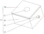
fig. 3 is a schematic structural view of a part of the accommodating device in the telescopic bracket for overhauling the substation equipment;
fig. 4 is the utility model provides a storage device inner structure schematic diagram in the telescoping shoring column for transformer substation equipment overhauls.
Illustration of the drawings: 1. a fixing plate; 2. a rectangular plate; 3. an adjustment device; 301. a rectangular block; 302. a spring; 303. a wire rope; 304. hooking the block; 305. turning the column; 306. a first round bar; 307. fixing a column; 308. a telescopic rod; 309. a rotating shaft; 310. a cylinder; 311. a guardrail; 312. a second round bar; 313. a support bar; 314. a motor; 315. a fixed block; 316. a connecting plate; 4. a storage device; 41. turning the hand; 42. a storage box; 43. rotating the block; 44. a circular ring; 45. a rope; 46. a hook; 47. a circular hole; 48. and (7) a box cover.
Detailed Description
In order to make the above objects, features and advantages of the present invention more clearly understood, the present invention will be further described with reference to the accompanying drawings and examples. It should be noted that the embodiments and features of the embodiments of the present application may be combined with each other without conflict.
In the following description, numerous specific details are set forth in order to provide a thorough understanding of the present invention, however, the present invention may be practiced in other ways than those specifically described herein, and therefore the present invention is not limited to the limitations of the specific embodiments of the present disclosure.
Embodiment 1, as shown in fig. 1-4, the utility model provides a telescopic bracket for transformer substation equipment overhauls, including fixed plate 1 and adjusting device 3, the fixed surface of fixed plate 1 is connected with rectangular plate 2, and rectangular plate 2 is vertical to be seted up flutedly, and the inside of rectangular plate 2 is equipped with adjusting device 3.
The specific arrangement and function of the adjusting device 3 and the storage device 4 will be described in detail below.
As shown in fig. 1 and 2, the adjusting device 3 includes a rectangular block 301, the surface of the rectangular block 301 is fixedly connected with the inner wall of the rectangular plate 2, the surface of the rectangular plate 2 is fixedly connected with two guard rails 311, the surfaces of the two guard rails 311 are uniformly and fixedly inserted with a second round rod 312, the interior of the second round rod 312 is hollow, the interior of the rectangular block 301 is hollow, two sides of the rectangular block 301 are uniformly and fixedly connected with springs 302, one end of the spring 302 far away from the rectangular block 301 is fixedly connected with a connecting plate 316, the surface of the connecting plate 316 is provided with a slot, a hook block 304 is slidably inserted in the slot, the surface of the connecting plate 316 is uniformly and fixedly connected with a cylinder 310, the surface of the cylinder 310 is uniformly and fixedly connected with a first round rod 306, two rotating shafts 309 are rotatably inserted in the connecting plate 316, the surfaces of the two rotating shafts are uniformly and fixedly connected with fixed columns 307, the telescopic link 308 is a big pipe, a little loop bar, and little loop bar slides at big pipe inside, the fixed surface of fixed plate 1 is connected with fixed block 315, the fixed surface of fixed plate 1 is connected and evenly is fixed with bracing piece 313, the bracing piece 313 is kept away from the one end of fixed plate 1 and is contacted with connecting plate 316 surface, and fixed block 315 is "L" shape, the fixed surface of fixed block 315 is connected with motor 314, motor 314's output fixedly connected with rotary column 305, the surperficial slip of rotary column 305 inserts the inside of establishing at rectangular block 301, the even fixedly connected with wire rope 303 in surface of rotary column 305, wire rope 303 keeps away from the one end fixedly connected with connecting plate 316 of rotary column 305.
The whole adjusting device 3 achieves the effect that when a plurality of devices at high altitude need to be overhauled by setting the adjusting device 3, the hook block 304 is pulled out to enable the hook block 304 to slide out of the connecting plate 316, at the moment, the spring 302 pushes the connecting plate 316 due to the return of elasticity, the connecting plate 316 slides out of the rectangular plate 2, at the moment, the steel wire rope 303 slides out of the rectangular plate 301 along with the connecting plate 316, the steel wire rope 303 slides out of the rectangular plate 301, the fixing column 307 is vertically arranged by rotating the rotating shaft 309, at the moment, the telescopic rod 308 is pulled to insert the telescopic rod 308 into the hollow second round rod 312, the connecting plate 316 slides out of the rectangular plate 2, when the work is finished, the telescopic rod 308 is pulled out of the second round rod 312, the fixing column 307 is received on the surface of the connecting plate 316 by rotating the rotating shaft 309, at the moment, the motor 314 is started, so that the motor 314 drives the rotating column 305 to rotate, at the rotating, thereby make in wire rope 303 pulls the connecting plate 316 into rectangular block 301, played the effect of taking in rectangular plate 2 with connecting plate 316, thereby solved when only alone overhauls equipment in the high altitude, probably because the elevating platform only has fixed size, thereby lead to the workman on the worker elevating platform can't overhaul as far as possible not enough equipment, examine equipment from the position that leads to falling the lift once more and remove the lift, the problem that the whole process was repaiied and is wasted time and energy
As shown in fig. 3 and 4, receiving device 4 is arranged on the surface of rectangular plate 2, receiving device 4 is including receiver 42, receiver 42's top is equipped with lid 48, and lid 48 and receiver 42 size looks adaptation, round hole 47 has been seted up on lid 48 surface, round hole 47 and rope 45 sliding connection, receiver 42's surface and rectangular plate 2 fixed connection, and receiver 42's upper end opening, receiver 42's inside is rotated and is inserted and be equipped with commentaries on classics piece 43, the surperficial rotation of commentaries on classics piece 43 is connected with rope 45, the fixed surface of commentaries on classics piece 43 is connected with commentaries on classics hand 41, the fixed surface of commentaries on classics hand 41 is connected with ring 44, the both ends fixedly connected with.
The effect that its whole storage device 4 reaches does, through setting up storage device 4, the workman is at the lift during operation, open lid 48 and hang hook 46 on ring 44, also can put into receiver 42 with the instrument of overhauing simultaneously, the effect of accomodating the instrument of overhauing at receiver 42 has been played, cover lid 48 this moment again and stimulate hook 46 and pull out hook 46 from receiver 42, hang hook 46 again on the safety clothing this moment, played and pulled the effect of avoiding carelessly dropping from the lift with the people, thereby the problem of the safety problem of people's work in the high altitude and the problem that the instrument of overhauing is played from the gap of guardrail 311 by the workman carelessly.
The integral working principle is that through the arrangement of the adjusting device 3, when a plurality of devices at high altitude need to be overhauled, the hook block 304 is pulled out to enable the hook block 304 to slide out of the connecting plate 316, at the moment, the spring 302 pushes the connecting plate 316 due to the return of elasticity, the connecting plate 316 slides out of the rectangular plate 2, at the moment, the steel wire rope 303 slides out of the rectangular plate 301 along with the connecting plate 316, the fixing column 307 is vertically placed by rotating the rotating shaft 309, at the moment, the telescopic rod 308 is pulled to insert the telescopic rod 308 into the hollow second round rod 312, the connecting plate 316 slides out of the rectangular plate 2, when the work is finished, the telescopic rod 308 is pulled out of the second round rod 312, the fixing column 307 is received on the surface of the connecting plate 316 by rotating the rotating shaft 309, at the moment, the motor 314 is started, so that the motor 314 drives the rotating column 305 to rotate, at the moment, the rotating column 305 pulls the steel wire rope, therefore, the steel wire rope 303 pulls the connecting plate 316 into the rectangular block 301, the effect of retracting the connecting plate 316 into the rectangular plate 2 is achieved, the problem that when only one person overhauls equipment, the lifting platform is fixed in size, so that workers on the lifting platform cannot overhaul the equipment which is as insufficient as possible, the equipment is inspected from the position where the lifting platform needs to be lowered again and the lifting platform needs to be moved, and the whole process is time-consuming and labor-consuming in maintenance is solved, when the workers work on the lifting platform, the box cover 48 is opened to hang the hook 46 on the ring 44, meanwhile, the maintenance tool can be placed into the storage box 42, the effect of storing the maintenance tool in the storage box 42 is achieved, the box cover 48 is covered again to pull the hook 46 out of the storage box 42, the hook 46 is hung on safety clothes, the effect of pulling the person to avoid carelessly dropping the lifting platform from the lifting platform is achieved, thereby solving the safety problem that people work at high altitude and the problem that the maintenance tools are carelessly kicked off from the gap of the guardrail 311 by workers.
The above description is only a preferred embodiment of the present invention, and is not intended to limit the present invention in other forms, and any person skilled in the art may use the above-mentioned technical contents to change or modify the equivalent embodiment into equivalent changes and apply to other fields, but any simple modification, equivalent change and modification made to the above embodiments according to the technical matters of the present invention will still fall within the protection scope of the technical solution of the present invention.
Claims (6)
1. A telescopic bracket for transformer substation equipment overhauls, including fixed plate (1) and adjusting device (3), its characterized in that: the surface of the fixing plate (1) is fixedly connected with a rectangular plate (2), the rectangular plate (2) is vertically provided with a groove, an adjusting device (3) is arranged in the rectangular plate (2), the adjusting device (3) comprises a rectangular block (301), the surface of the rectangular block (301) is fixedly connected with the inner wall of the rectangular plate (2), the interior of the rectangular block (301) is hollow, springs (302) are uniformly and fixedly connected to the two sides of the rectangular block (301), one end, far away from the rectangular block (301), of each spring (302) is fixedly connected with a connecting plate (316), a clamping groove is formed in the surface of each connecting plate (316), a hook block (304) is inserted in the clamping groove in a sliding manner, a cylinder (310) is uniformly and fixedly connected to the surface of each connecting plate (316), a first round rod (306) is uniformly and fixedly connected to the surface of each cylinder (310), two rotating shafts (309) are inserted in the connecting plates (316), the surfaces of the two rotating shafts (309) are uniformly and fixedly connected with fixing columns (307), and the surfaces of the fixing columns (307) are uniformly and fixedly connected with telescopic rods (308).
2. The telescopic bracket for overhaul of substation equipment according to claim 1, wherein: the fixed surface of rectangular plate (2) is connected with two guardrails (311), two the surface of guardrail (311) is evenly fixed to run through and has been inserted second round bar (312), and the inside of second round bar (312) is hollow.
3. The telescopic bracket for overhaul of substation equipment according to claim 1, wherein: the fixed surface of fixed plate (1) is connected with fixed block (315), and fixed block (315) are "L" shape, the fixed surface of fixed block (315) is connected with motor (314), the output fixedly connected with rotary column (305) of motor (314), the surperficial slip of rotary column (305) is inserted and is established the inside of rectangle piece (301), the even fixedly connected with wire rope (303) in surface of rotary column (305), the one end fixedly connected with connecting plate (316) of rotary column (305) is kept away from in wire rope (303).
4. The telescopic bracket for overhaul of substation equipment according to claim 1, wherein: the surface of the fixed plate (1) is fixedly connected with supporting rods (313) uniformly, and one end, far away from the fixed plate (1), of each supporting rod (313) is in contact with the surface of the connecting plate (316).
5. The telescopic bracket for overhaul of substation equipment according to claim 1, wherein: the surface of rectangular plate (2) is equipped with storage device (4), storage device (4) are including receiver (42), the surface and rectangular plate (2) fixed connection of receiver (42), and the upper end opening of receiver (42), the inside rotation of receiver (42) is inserted and is equipped with commentaries on classics piece (43), the surperficial rotation of commentaries on classics piece (43) is connected with rope (45), the fixed surface who changes piece (43) is connected with changes hand (41), the fixed surface who changes hand (41) is connected with ring (44), the both ends fixedly connected with hook (46) of rope (45).
6. The telescopic bracket for overhaul of substation equipment according to claim 5, wherein: the top of receiver (42) is equipped with lid (48), and lid (48) and receiver (42) size looks adaptation, round hole (47) have been seted up on lid (48) surface, round hole (47) and rope (45) sliding connection.
Priority Applications (1)
| Application Number | Priority Date | Filing Date | Title |
|---|---|---|---|
| CN202021595266.2U CN212669157U (en) | 2020-08-04 | 2020-08-04 | Telescopic bracket for overhauling substation equipment |
Applications Claiming Priority (1)
| Application Number | Priority Date | Filing Date | Title |
|---|---|---|---|
| CN202021595266.2U CN212669157U (en) | 2020-08-04 | 2020-08-04 | Telescopic bracket for overhauling substation equipment |
Publications (1)
| Publication Number | Publication Date |
|---|---|
| CN212669157U true CN212669157U (en) | 2021-03-09 |
Family
ID=74820893
Family Applications (1)
| Application Number | Title | Priority Date | Filing Date |
|---|---|---|---|
| CN202021595266.2U Expired - Fee Related CN212669157U (en) | 2020-08-04 | 2020-08-04 | Telescopic bracket for overhauling substation equipment |
Country Status (1)
| Country | Link |
|---|---|
| CN (1) | CN212669157U (en) |
Cited By (1)
| Publication number | Priority date | Publication date | Assignee | Title |
|---|---|---|---|---|
| CN113872091A (en) * | 2021-11-09 | 2021-12-31 | 国网山东省电力公司莘县供电公司 | Lifting maintenance cart for maintenance of vacuum circuit breaker |
-
2020
- 2020-08-04 CN CN202021595266.2U patent/CN212669157U/en not_active Expired - Fee Related
Cited By (1)
| Publication number | Priority date | Publication date | Assignee | Title |
|---|---|---|---|---|
| CN113872091A (en) * | 2021-11-09 | 2021-12-31 | 国网山东省电力公司莘县供电公司 | Lifting maintenance cart for maintenance of vacuum circuit breaker |
Similar Documents
| Publication | Publication Date | Title |
|---|---|---|
| CN212669157U (en) | Telescopic bracket for overhauling substation equipment | |
| CN210263850U (en) | Novel building and erecting frame | |
| CN210313390U (en) | Transformer overhauls with overhauing frame | |
| CN211850741U (en) | A safe hanging flower basket for high-rise outer wall fitment construction | |
| CN103950872B (en) | The vertical rod lifting multi-purpose tool of a kind of electric substation high-altitude equipment | |
| CN214299167U (en) | Electric power safety construction operation platform | |
| CN212562370U (en) | Scaffold for building construction | |
| CN211201101U (en) | Movable construction platform for bridge foundation construction | |
| CN210759347U (en) | Mounting equipment | |
| CN211004327U (en) | Portable pole wire lifter | |
| CN211007559U (en) | A multi-functional lift platform for construction | |
| CN208200107U (en) | A kind of escalator or moving sidewalk electric cabinet auxiliary lifting apparatus | |
| CN112174056A (en) | Protective lifting equipment for machining equipment | |
| CN220267155U (en) | Adjustable scaffold | |
| CN216428988U (en) | A safe suspended structure for high altitude construction is built in room | |
| CN220599094U (en) | Concrete placement workstation is built in municipal house | |
| CN217812243U (en) | Building construction platform that stability is good | |
| CN220149173U (en) | Anti-falling device of stacker | |
| CN215626609U (en) | Upper frame maintenance hanging basket | |
| CN219730481U (en) | Electric power facility overhauls device | |
| CN109184206B (en) | Special-purpose regular frame convenient for lifting climbing formwork steel forms | |
| CN218149624U (en) | But height-adjusting's stable form construction frame | |
| CN218815094U (en) | Scaffold for building construction | |
| CN219261698U (en) | Stable integral climbing steel platform die carrier | |
| CN218620243U (en) | Maintenance elevation structure |
Legal Events
| Date | Code | Title | Description |
|---|---|---|---|
| GR01 | Patent grant | ||
| GR01 | Patent grant | ||
| CF01 | Termination of patent right due to non-payment of annual fee | ||
| CF01 | Termination of patent right due to non-payment of annual fee |
Granted publication date: 20210309 Termination date: 20210804 |