CN212642996U - Noise elimination air pump device - Google Patents
Noise elimination air pump device Download PDFInfo
- Publication number
- CN212642996U CN212642996U CN202021293741.0U CN202021293741U CN212642996U CN 212642996 U CN212642996 U CN 212642996U CN 202021293741 U CN202021293741 U CN 202021293741U CN 212642996 U CN212642996 U CN 212642996U
- Authority
- CN
- China
- Prior art keywords
- filter
- silencer
- air
- diaphragm pump
- air inlet
- Prior art date
- Legal status (The legal status is an assumption and is not a legal conclusion. Google has not performed a legal analysis and makes no representation as to the accuracy of the status listed.)
- Active
Links
Images


Abstract
The utility model provides a noise elimination air pump device, which comprises a shell component, a clapboard, a silencer, a filter and a diaphragm pump, and is characterized in that the silencer, the filter and the diaphragm pump are sequentially connected, the clapboard divides the interior of the shell component into an air inlet area A and an air exhaust area B, the silencer and the filter are arranged in the air inlet area A, and the diaphragm pump is arranged in the air exhaust area B; the gas in the gas source is connected into the silencer, and the gas enters the diaphragm pump after being filtered by the filter and is output by the diaphragm pump according to the specified discharge capacity. The silencer is used for air inlet noise reduction, and soundproof cotton is used for noise reduction of the diaphragm pump, so that the noise of the equipment is reduced to a reasonable range.
Description
Technical Field
The utility model relates to an air pump field especially relates to the diaphragm pump field.
Background
The diaphragm pump is a reciprocating pump which is divided into two parts which are not communicated with each other by an elastic film, corrosion-resistant rubber or an elastic metal sheet. Before the gas in the gas source is connected into the equipment, the gas moves at a high speed in the gas pipe, and the mouth of the gas pipe has great noise; meanwhile, when the diaphragm pump works, noise is also generated, the noise causes discomfort of a user, and the noise reduction is urgent.
Disclosure of Invention
In order to overcome the problems in the background art, the utility model provides a noise elimination air pump device, which comprises a shell component, a clapboard, a silencer, a filter and a diaphragm pump, wherein the silencer, the filter and the diaphragm pump are sequentially connected, the clapboard divides the interior of the shell component into an air inlet area A and an air exhaust area B, the silencer and the filter are arranged in the air inlet area A, and the diaphragm pump is arranged in the air exhaust area B; the gas in the gas source is connected into the silencer, and the gas enters the diaphragm pump after being filtered by the filter and is output by the diaphragm pump according to the specified discharge capacity.
The shell component comprises a bottom plate, a side plate and a top cover, wherein the side plate is fixed with the bottom plate, and the top cover is connected to the side plate through a screw; the bottom plate is provided with a filter water outlet hole and a silencer air inlet hole, and the side plate is provided with an air pipe sheath and a power plug.
The bottom plate is provided with a first positioning groove, the side plate is provided with a second positioning groove, the top cover is provided with a third positioning groove, and the partition plate is positioned by the first positioning groove, the second positioning groove and the third positioning groove.
The clapboard is provided with an air pipe through hole.
A silencer fixing frame and a filter mounting seat are further arranged in the air inlet area A, the filter mounting seat is arranged above the water outlet hole of the bottom plate filter, and the filter mounting seat is provided with a positioning hole matched with the filter in a profiling mode; the silencer fixing frame is connected with the filter mounting seat through screws, and the air inlet of the silencer corresponds to the air inlet of the silencer on the bottom plate.
The diaphragm pump outside is equipped with the sound-proof box, and the sound-proof box is made by soundproof cotton.
The diaphragm pump is connected with the shell subassembly through the shock pad, and the intake pipe of diaphragm pump links to each other with the filter, and the outlet duct is worn to locate in the trachea sheath.
A foot pad is also arranged on the lower side of the shell component.
The utility model has the advantages that:
when air is fed, the noise of the gas provided by the gas source is reduced through the silencer; meanwhile, noise reduction is carried out on the diaphragm pump by using soundproof cotton; through the two measures, the noise of the equipment is greatly reduced, and the noise of the equipment is reduced to a reasonable range.
Drawings
The accompanying drawings, which are included to provide a further understanding of the invention and are incorporated in and constitute a part of this specification, illustrate embodiments of the invention and together with the description serve to explain the invention without limiting the invention in which:
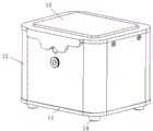
FIG. 1 is a schematic view of an enclosure assembly;
FIG. 2 is a top plan view of the muffling air pump assembly with the top cover removed;
FIG. 3 is a schematic view of the noise-abating air pump assembly with the top cover and sound isolation box removed;
FIG. 4 is a schematic view of the layout and connection of the interior of the noise-reduction air pump device;
FIG. 5 is a schematic view of a housing assembly chassis;
FIG. 6 is a schematic illustration of side panels of the enclosure assembly;
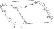
FIG. 7 is a schematic illustration of a top cover of the housing assembly;
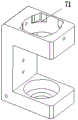
FIG. 8 is a schematic view of a filter mount;
FIG. 9 is a schematic view of a muffler mounting bracket.
Description of reference numerals:
1-shell component, 2-partition board, 3-silencer, 4-filter, 5-diaphragm pump, 6-silencer fixing frame, 7-filter mounting seat, 8-sound insulation box, 11-bottom board, 12-side board, 13-top cover, 14-foot pad, 21-air pipe via hole, 71-locating hole, 111-filter water outlet hole, 112-silencer air inlet hole, 113-first locating groove, 121-air pipe sheath, 122-power plug, 123-second locating groove, 131-third locating groove, A-air inlet area and B-air outlet area.
Detailed Description
The following detailed description of the embodiments of the present invention is provided in conjunction with the accompanying drawings, and it is to be understood that the embodiments described herein are merely illustrative and explanatory of the invention, and are not restrictive thereof.
As shown in fig. 1 to 9, a muffling air pump device includes a housing assembly 1, a partition plate 2, a muffler 3, a filter 4, and a diaphragm pump 5, wherein the muffler 3, the filter 4, and the diaphragm pump 5 are sequentially connected, the partition plate 2 partitions the interior of the housing assembly 1 into an air intake area a and an air exhaust area B, the muffler 3 and the filter 4 are disposed in the air intake area a, and the diaphragm pump 5 is disposed in the air exhaust area B; the gas in the gas source is connected into the silencer 3, and the gas enters the diaphragm pump 5 after being filtered by the filter 4 and then is output by the diaphragm pump 5 according to the specified discharge capacity.
The shell assembly 1 comprises a bottom plate 11, a side plate 12 and a top cover 13, wherein the side plate 12 is fixed with the bottom plate 11, and the top cover 13 is connected to the side plate 12 through a screw; the bottom plate 11 is provided with a filter water outlet 111 and a silencer air inlet 112, and the side plate 12 is provided with an air pipe sheath 121 and a power plug 122.
The bottom plate 11 is provided with a first positioning groove 113, the side plate 12 is provided with a second positioning groove 123, the top cover 13 is provided with a third positioning groove 131, and the partition plate 2 is positioned by the first positioning groove 113, the second positioning groove 123 and the third positioning groove 131.
The clapboard 2 is provided with an air pipe through hole 21.
A silencer fixing frame 6 and a filter mounting seat 7 are further arranged in the air inlet area A, the filter mounting seat 7 is arranged above the filter water outlet hole 111 of the bottom plate 11, and the filter mounting seat 7 is provided with a positioning hole 71 matched with the filter 4 in a copying manner; the silencer fixing frame 6 is connected with the filter mounting seat 7 through screws, and an air inlet of the silencer 3 corresponds to a silencer air inlet 112 on the bottom plate 11.
The diaphragm pump 5 is externally provided with a soundproof box 8, and the soundproof box 8 is made of soundproof cotton.
Preferably, the soundproof box 8 is made of soundproof cotton into a square box with a hollow inside.
The diaphragm pump 5 is connected with the shell component 1 through a damping pad; the air inlet pipe of the diaphragm pump 5 is connected with the filter 4, and the air outlet pipe penetrates through the air pipe sheath 121.
Preferably, the housing assembly 1 is further provided with a foot pad 14.
Finally, it should be noted that: the above embodiments are only used to illustrate the technical solution of the present invention and not to limit it; although the present invention has been described in detail with reference to preferred embodiments, it will be understood by those skilled in the art that various changes in form and details may be made therein without departing from the spirit and scope of the invention; without departing from the spirit of the present invention, it should be understood that the scope of the claims is intended to cover all such modifications and variations.
Claims (8)
1. A silencing air pump device comprises a shell component (1), a partition plate (2), a silencer (3), a filter (4) and a diaphragm pump (5), and is characterized in that the silencer (3), the filter (4) and the diaphragm pump (5) are sequentially connected, the partition plate (2) divides the interior of the shell component (1) into an air inlet area A and an air outlet area B, the silencer (3) and the filter (4) are arranged in the air inlet area A, and the diaphragm pump (5) is arranged in the air outlet area B; the gas in the gas source is connected into the silencer (3), and the gas enters the diaphragm pump (5) after being filtered by the filter (4), and then is output by the diaphragm pump (5) according to the specified discharge capacity.
2. A muffling air pump device according to claim 1, wherein the housing assembly (1) comprises a bottom plate (11), a side plate (12) and a top cover (13), the side plate (12) is fixed to the bottom plate (11), and the top cover (13) is connected to the side plate (12) by screws; the bottom plate (11) is provided with a filter water outlet hole (111) and a silencer air inlet hole (112), and the side plate (12) is provided with an air pipe sheath (121) and a power plug (122).
3. A muffling air pump device according to claim 2, wherein the bottom plate (11) is provided with a first positioning groove (113), the side plate (12) is provided with a second positioning groove (123), the top cover (13) is provided with a third positioning groove (131), and the partition (2) is positioned by the first positioning groove (113), the second positioning groove (123) and the third positioning groove (131).
4. A muffling air pump device according to claim 1, wherein an air pipe passing hole (21) is provided on the partition plate (2).
5. The muffling air pump device according to claim 1, wherein a muffler fixing frame (6) and a filter mounting seat (7) are further arranged in the air inlet area A, the filter mounting seat (7) is arranged above the filter water outlet hole (111) of the bottom plate (11), and the filter mounting seat (7) is provided with a positioning hole (71) matched with the filter (4) in a profiling manner; the silencer fixing frame (6) is connected with the filter mounting seat (7) through screws, and the air inlet of the silencer (3) corresponds to the silencer air inlet (112) on the bottom plate (11).
6. A sound-damping air pump device according to claim 1, characterised in that the membrane pump (5) is externally provided with a sound-insulating box (8), the sound-insulating box (8) being made of acoustic cotton.
7. A sound-damping air pump device according to claim 1, characterised in that the membrane pump (5) is connected to the housing assembly (1) via a shock-absorbing pad; an air inlet pipe of the diaphragm pump (5) is connected with the filter (4), and an air outlet pipe penetrates through the air pipe sheath (121).
8. A muffling air pump device according to claim 1 or 2, characterized in that the housing assembly (1) is further provided with a foot mat (14).
Priority Applications (1)
| Application Number | Priority Date | Filing Date | Title |
|---|---|---|---|
| CN202021293741.0U CN212642996U (en) | 2020-07-06 | 2020-07-06 | Noise elimination air pump device |
Applications Claiming Priority (1)
| Application Number | Priority Date | Filing Date | Title |
|---|---|---|---|
| CN202021293741.0U CN212642996U (en) | 2020-07-06 | 2020-07-06 | Noise elimination air pump device |
Publications (1)
| Publication Number | Publication Date |
|---|---|
| CN212642996U true CN212642996U (en) | 2021-03-02 |
Family
ID=74784382
Family Applications (1)
| Application Number | Title | Priority Date | Filing Date |
|---|---|---|---|
| CN202021293741.0U Active CN212642996U (en) | 2020-07-06 | 2020-07-06 | Noise elimination air pump device |
Country Status (1)
| Country | Link |
|---|---|
| CN (1) | CN212642996U (en) |
-
2020
- 2020-07-06 CN CN202021293741.0U patent/CN212642996U/en active Active
Similar Documents
| Publication | Publication Date | Title |
|---|---|---|
| WO2020024522A1 (en) | Sound generation apparatus and portable terminal | |
| CN105509292A (en) | Active ventilation muffler | |
| CN212642996U (en) | Noise elimination air pump device | |
| CN214614692U (en) | Sound insulation assembly for opera house | |
| CN213838830U (en) | Vacuum pump with noise reduction function | |
| CN110843831A (en) | Distribution box, air conditioner pipe system and air conditioner of making an uproar fall | |
| CN214944500U (en) | Energy-saving environment-friendly noise reduction silencer | |
| CN214616927U (en) | Noise-reducing and shock-absorbing compressor assembly for oxygenerator | |
| CN204783178U (en) | Exhausting silencer | |
| JP3178228B2 (en) | Oxygen concentrator | |
| CN203867673U (en) | Active noise control system used for automobile exhaust system | |
| CN215298853U (en) | Noise elimination and vibration isolation device for thermal power plant | |
| CN210885303U (en) | Modular machine core structure of oxygenerator | |
| CN210663235U (en) | New trend silencing device of system | |
| CN219872868U (en) | Active noise reduction device | |
| CN218717515U (en) | Silencing mechanism for dry-type screw compressor | |
| CN103982281A (en) | Active noise control system and method for automobile exhaust system | |
| CN212079753U (en) | Noise-reducing and noise-reducing dust remover | |
| CN220953965U (en) | Green construction noise suppression device | |
| CN217270693U (en) | Amortization subassembly, compressor and refrigeration plant | |
| CN220037078U (en) | Vacuum exhaust noise eliminator for optical plotter | |
| CN218757960U (en) | Sound insulation room for compressor test | |
| CN216430077U (en) | Composite silencing box of axial flow fan | |
| CN220165831U (en) | Oxygenerator with mute structure | |
| CN220487693U (en) | Novel muffler structure |
Legal Events
| Date | Code | Title | Description |
|---|---|---|---|
| GR01 | Patent grant | ||
| GR01 | Patent grant |